Table of Contents
Advertisement
Quick Links
Document Copyrights
Copyright 2006 by Kenwood Corporation. All rights reserved.
No part of this manual may be reproduced, translated, distributed, or transmitted in any
form or by any means, electronic, mechanical, photocopying, recording, or otherwise, for
any purpose without the prior written permission of Kenwood.
Disclaimer
While every precaution has been taken in the preparation of this manual, Kenwood
assumes no responsibility for errors or omissions. Neither is any liability assumed for
damages resulting from the use of the information contained herein. Kenwood reserves
the right to make changes to any products herein at any time for improvement purposes.
Advertisement
Table of Contents

Related Manuals for Kenwood KMC-38GPS


Summary of Contents for Kenwood KMC-38GPS
- Page 1 Kenwood. Disclaimer While every precaution has been taken in the preparation of this manual, Kenwood assumes no responsibility for errors or omissions. Neither is any liability assumed for damages resulting from the use of the information contained herein. Kenwood reserves...
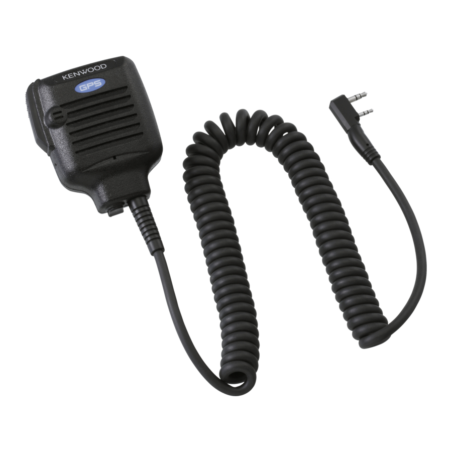
- Page 2 GPS SPEAKER MICROPHONE KMC-38GPS SERVICE MANUAL © 2006-9 PRINTED IN JAPAN B51-8768-00 ( N ) 516 Lever (PTT) (D10-0629-08) Dressed screw (N08-0547-08) SPECIFICATIONS CIRCUIT DESCRIPTION Microphone The location data is calculated by the GPS unit and is then sent to the transceiver via the RXD terminal of the universal Impedance .............
- Page 3 BAND WHEN REPLACING THE BUILT-IN BATTERY IN OR- DER TO PREVENT STATIC DISCHARGE. THE INSTALLED IC MAY BE DAMAGED BY A DISCHARGE OF STATIC ELEC- TRICITY. 1. Remove the KMC-38GPS from the transceiver and 4 screws on the rear panel. GPS Unit GPS Unit 2.
- Page 4 1. Prepare the TK-2180 transceiver. (Set the GPS Position Display to a key, such as the [S] key, with the FPU before- hand.) 2. Connect the KMC-38GPS to the universal connector on the transceiver. 3. Turn the transceiver power ON.
- Page 5 KMC-38GPS SCHEMATIC DIAGRAM SUB UNIT (W02-3720-08) UNIVERSAL CONNECTOR CORD CIRCUIT SP– MICE SP– VCC 5V MICE SP– (R17) Vcc 5V MICROPHONE UNIT (W02-3720-08) 2.2k R5 68k 10µ/16V – 10µ/16V MAIN MICE VCC 5V 2.7k 10µ/ PTT SWITCH UNIT (W02-3720-08) SP–...
- Page 6 KMC-38GPS EXPLODED VIEW 701 STICKER 706 GPS UNIT PTT SWITCH UNIT 36x4 SPACER 40x2 35x4 SPACER 702 HOLDER x2 37x3 MICROPHONE UNIT RECTANGULAR PLUG 707 PACKING 700 PLASTIC CABINET SUB UNIT CORD ASSY WITH PLUG ∗1: In order to maintain the waterproofing performance, the cord ASSY with plug cannot be replaced.
-
Page 7: Parts List
Unit 3712-3724, Level 37, Tower one Metroplaza, 223 Hing Fong Road, Bp 58416 Villepinte, 95944 Roissy Ch De Gaulle Cedex Kwai Fong, N.T., Hong Kong KENWOOD House, Dwight Road, Watford, Herts., 1 Ang Mo Kio Street 63, Singapore 569110 WD18 9EB United Kingdom...
Need help?
Do you have a question about the KMC-38GPS and is the answer not in the manual?
Questions and answers