Table of Contents
Advertisement
Quick Links
Video Security Intercom System for the Home
Rough - In Instructions
VMC1
POWER
BAND
MEM ALARM DOWN
UP
1
2
3
4
5
+
5
ME-UP
TUNER
AUX MUSIC
RADIO FILTER
GATE STATUS
AUX OUTPUT 1
AUX OUTPUT 2
USA & Canada (800) 421-1587 & (800) 392-0123
(760) 438-7000 - Toll Free FAX (800) 468-1340
www.linearcorp.com
+
-
VOLUME
2
3
4
1
AUX 2
AUX 1
INPUT
FILTER
6
7
5
VID 1
VID 3
LOCK
VID 2
MUS
PRIV
MON
CLEAR
HOUSE
DOOR
AUX
Advertisement
Table of Contents

Subscribe to Our Youtube Channel
Related Manuals for M&S Systems VMC1


Summary of Contents for M&S Systems VMC1
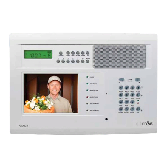
- Page 1 VMC1 Video Security Intercom System for the Home POWER BAND MEM ALARM DOWN ME-UP TUNER VOLUME AUX MUSIC RADIO FILTER AUX 2 AUX 1 INPUT FILTER GATE STATUS VID 1 VID 3 LOCK VID 2 AUX OUTPUT 1 PRIV AUX OUTPUT 2...
- Page 2 Grounding or Polarization - Precautions should be taken so that the grounding or polarization means of an appliance is not defeated. Keep this manual in a safe place for future reference. To replace this manual, download available from Linear Web site:www.linearcorp.com...
- Page 3 ✔ DO Use Cat-5 wire for all VMC1 wire runs. ✔ DO NOT step on Cat-5 cable during installation. ✔ DO label all wire runs. Connecting the wires to the VMC1 ✔ DO NOT overtighten the cable ties, apply cable ties loosely, master, room station, or door station incorrectly may result with random spacing.
-
Page 4: Table Of Contents
The VMC1 System ........ -
Page 5: Block Diagram
Block Diagram ROOM STATION VOLUME AM ANTENNA PRIV CLEAR HOUSE DOOR FM ANTENNA ROOM STATION VOLUME PRIV DOOR CLEAR HOUSE DOOR STATION POWER BAND MEM ALARM DOWN ME-UP TUNER VOLUME AUX MUSIC RADIO FILTER AUX 1 AUX 2 INPUT FILTER GATE STATUS VID 1 VID 2... -
Page 6: Introduction
Introduction The VMC1H installation rough-in prepares the home to accommodate the video intercom system. A VMC1MB mounting bracket is necessary for the Master Station. Room stations and the Alloy Color Video Door Station (VMC1VDS) can be mounted directly onto fi nished walls. All other door stations require a rough-in enclosure (VMC1HR). -
Page 7: Materials Required
Materials Required Tools Most are required for purposes of this installation, but may vary according to installer preferences. WIRE STRIPPERS/CUTTER POWER DRILL WITH 1” AUGER 110 PUNCH-DOWN TOOL PHILLIPS SCREWDRIVER TAPE MEASURE 14/18 GAUGE WIRE CAT-5 CABLE COAX CABLE LEVEL MOUNTING SCREWS DRYWALL SAW (VARIOUS SIZES) -
Page 8: Overview
Overview The VMC1 System Room Stations Designed for installation in new homes, the VMC1 is a Whole To avoid audio feedback, Room Stations should be kept at least House Color Video Security Intercom system that provides 10 feet away from other stations. Never have more than one... -
Page 9: Wiring Information
Wiring Information Cable Type and Confi guration Cables and Wiring Excellent locations to run cables include: The general intercom functions for VMC1 can be cabled using Cat-5 or Cat-6 cables. If required, 6-conductor telephone • Roof space cables can be used provided the system is confi gured for •... -
Page 10: Master Station Rough-In
Master Station Rough-In VMC1MB Master Station Mounting Bracket VMC1MB Installation - Unfi nished Wall The VMC1MB mounts fl ush with the wall stud and holds the Install the VMC1MB fl ush with the front of the wall stud and Master Station and Power Supply (See Figure 1). Position the fasten in place with screws as shown. -
Page 11: Vmc1Mb Installation - Finished Wall
Master Station Rough-In VMC1MB Installation - Finished Wall Cut out an opening in the drywall (Height 7-1/4” x Width 11”) but do not cut right up against the wall stud. Allow 5/8” clearance between drywall opening and stud. This ensures that drywall will overlap bracket (See Figure 2). -
Page 12: Room Station Rough-In
Station location. Following this color convention will assist in in Enclosure and make a knot so they do not fall back into the the fi nal installation of the VMC1 system. wall once the drywall is installed. Pull the yellow wire through the hole in the back of the... -
Page 13: Door Station Rough-In
Door Station Rough-In VMC1VDS Door Station Rough-in 1. Identify the location where the VMC1VDS is to be installed. The VMC1VDS is a metal door station with a 90 degree horizontal viewing area. It is normally mounted at a height 2. Pull Cat-5 wire from the VMC1MB to this location. from the fl... -
Page 14: Door Station Rough-In
For added protection against weather, the VMC1VDS-S and to be utilized, see “Door Release Rough-in and “Chime VMC1VDS-BZ should be equipped with a DSWS weather Activated CO Rough-in shield. The installation of the DSWS is provided in the VMC1 Finish Out Guide. PRE-DRYWALL COLOR VIDEO DOOR STATION... -
Page 15: Power Supply Rough-In
Power Supply Rough-In TE6D Power Supply Power Supply Connections The Power Supply unit is pre-wired and self contained, and The 6-pin connector is the low voltage (13.8 VDC, 3.8 amp) the wires are tucked inside. To access connection wires, open output from the TE6D Power Supply unit: the Power Supply unit by removing four screws as shown •... -
Page 16: Power Supply Wiring
15-amp circuit breaker to the Master 6. Tuck cables into the Power Supply enclosure. Station Mounting Bracket location. The VMC1 requires a 7. Pull the Red and Black low voltage wires out of the top dedicated power source so there’s no interference from of the TE6D for later connection to the Master Station. -
Page 17: Data Hub Wiring
Pull all the Door and Room Station cables to the location of Cat-5 WIRE COLOR MODULAR PLUG the Master Station Mounting Bracket (VMC1MB). If the installation consists of more than 5 room stations, Linear Pin 1 White/Green recommends using the optional Linear DMD-16 (16 stations) -
Page 18: Antenna Installation
3. Route the connector end of the antenna COAX down through the hole in the ceiling plate, down the stud bay, and on the right side of where the VMC1 Master Unit will be installed. 4. Connect the included 75 Ohm to 300 Ohm adapter to the... -
Page 19: Auxiliary Output Rough-In
Auxiliary Output Rough-In Door Release Rough-in Chime Activated Control Output Rough-In The Door Release Trigger can be activated from the VMC1 The Chime Activated Control Output allows for any number of Master or any remote room station by pressing the Lock security related automation functions including 10 available button. -
Page 20: Appendix A - Available Components
5.6” TFT LED color screen supporting up to 20 remote stations. Point-to-Point, Point-to-Group and All Call intercom with hands free response. UL 60950 certifi ed VMC1 (White pictured) VMC1-BK (Black) VMC1-BZ (Bronze) Color Video Door Station with 10 different door chimes, 90º horizontal and 50º... - Page 21 Appendix A – Available Components Starter Kit for VMC1 Security Intercom System one (1) Master, one (1) Alloy Door Station and four (4) room stations White(VMC1PACK) Non-video door station. Basic doorbell intercom station where video is not required. Standard weather resistance IP30...
- Page 22 Appendix A – Available Components Mounting bracket for VMC1 Master Steel (VMC1MB) Rough in kit for the VMC1 Master. Includes mounting frame, TE6D power supply, FM Dipole antenna, AM antenna wire and installation hardware (VMC1H) Metal mounting box for room and video stations...
- Page 23 Appendix A – Available Components Electronic Door Release w/power supplies Remote Door Lock (DRW) 12V Control Output switched 110V outlets for lights and other “notifi cation” devices Remote Turn On for Lights AC1 (1 outlet) AC3 (2 outlets) MFG: Xantec/Niles 2-Channel Receiver (DXR-702) Miniature door / window transmitter (DXS-32)
-
Page 24: Year Limited Warranty
United States. There exclusion or limitation of consequential, incidental or special are no obligations or liabilities on the part of Linear LLC for damages, so the above limitation or exclusion may not apply consequential damages arising out of or in connection with to you.
Need help?
Do you have a question about the VMC1 and is the answer not in the manual?
Questions and answers