Table of Contents
Advertisement
Quick Links
Download this manual
See also:
Instruction Manual
Advertisement
Table of Contents

Related Manuals for M&S Systems VMC1


Summary of Contents for M&S Systems VMC1
-
Page 1: Quick Start Guide
VMC1 Video Security Intercom & Music System Quick Start Guide VMC1 Video Security Intercom system for the home USA & Canada (800) 421-1587 & (800) 392-0123 (760) 438-7000 - Toll Free FAX (800) 468-1340 www.linearcorp.com... - Page 2 Warning: Always follow these safety instructions. Retain these instructions for future system reference. DO NOT expose the VMC1 to moisture or fi re or shock hazards can occur, and impair the warranty. DO NOT expose Stations to direct water spray or damage will occur...
-
Page 3: Table Of Contents
LOCK VID 1 VID 3 VID 2 GREEN Status RED Status PRIV CLEAR HOUSE DOOR Keep this manual in a safe place for future reference. If you lose the manual, you can download it from the Linear Web site: www.linearcorp.com... -
Page 4: Quick Start Guide: Intercom
NOTE: Door Stations calls are only initiated from the Door Station. Room to Room Calling All Stations in the VMC1 system have an ID number. Press this number to talk or page another station and have a “private” conversation. - Page 5 Stations have an I.D. from: Press two digits for the Station to talk to. RED Status or 31 to 37 LED blinks at all Stations to indicate the VMC1 system is active. NOTE: Only one conversation can be active at a time.
-
Page 6: Quick Start Guide: Music & Audio
Quick Start Guide: Music & Audio NOTE: VMC1 does not distinguish between audio from a room being monitored and audio from the tuner. If a room is to be monitored, it is recommended that the tuner be turned off. Set Volume Level at Master Station To change the speaker volume at the Master Station: 1. - Page 7 2. Press BAND button to select AM or FM. 3. Press DOWN & UP buttons to tune the desired radio frequency. Store Radio Stations VMC1 saves up to ten AM and ten FM stations. 1. Press Band to select AM or FM 2. Press and release MEM button 3.
-
Page 8: Quick Start Guide: Clock Radio
Quick Start Guide: Clock Radio 2. Use the DOWN and UP buttons to adjust the desired minutes for the alarm operation 3. Press the ALARM button again to switch to hours. The Hours will begin to blink 4. Use the DOWN and UP buttons to adjust the desired hour for the alarm to activate 5. -
Page 9: Master Station Video Display Operation
Quick Start Guide: Video Master Station Video Display Operation To see the camera view for any of the three attached cameras on the Master Station: 1. Press AUX followed by the desired video source 2. Press 5 for VID1, 3. 6 for VID2 4. -
Page 10: Nightstand Station - Audio Input
NOTE: See P.2 of Help menu to view the second function of certain keypad buttons in conjunction with the ‘7’ button (Applicable to Double Digit format Only) Optional Functions The VMC1 Security Intercom is equipped with functions that require additional accessories. Ask you installer if these functions are enabled at your installation. - Page 11 Quick Start Guide: Options Door Release The VMC1 Security Intercom System supports up to three remote electronic door release mechanisms. To activate a door release: 1. Press the Door Chime button at a Video Door Station. The RED Status LED blinks at all Stations indicating an active Page 2.
-
Page 12: Master Station Power Up
4. Press plus or minus buttons* to navigate up or down LOCK 5. Press up or down keys* to alter value 6. Use PREV/NEXT MENU to navigate between menus Programming Steps To program your VMC1 system, please refer to the Finish Out Guide that came with your installation package. -
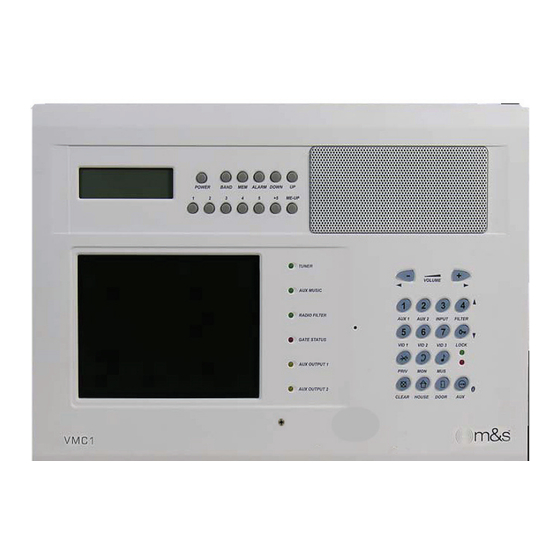
Page 13: Master Station Diagram
Master Station Diagram Table 1 Master Station Functions Key Description Button Primary Function Aux Function Display for Clock Radio Clock Radio Shows Time Shows Radio Keypad Station Clock Radio Keypad Band Switch AM/FM 5.6 Color LCD 5,6,7 Displays Video Displays Door Video screen VID 1,2,3 Video Cam... -
Page 14: Intercom Keypad
Intercom Keypad Buttons/Icons Table 2 Intercom Keypad Function Keys Primary Function Aux Function Volume Control Sets volume at Master for (L) Low to (M) Program Mode Radio and Medium to (H) Intercom High Number Keys Station ID Aux 1 Auxilliary Function Aux 2 Input Filter... -
Page 15: Led Indicator Lights
LED Indicator Lights LED Lights (Light emitting Diodes) indicate status or activity by alerting user with ON/OFF functions, blinking or fl ashing to indicate active status, and auxiliary music sources are active. They are the status lights for the system and are these colors when not functioning: Tuner - Green Aux Music - Green... -
Page 16: Limited Warranty
This limited warranty gives you specifi c legal rights, and you may also have other rights, which vary from state to state. This Linear LLC Warranty is in lieu of all other warranties express or implied.
Need help?
Do you have a question about the VMC1 and is the answer not in the manual?
Questions and answers