Table of Contents
Advertisement
Advertisement
Table of Contents

Subscribe to Our Youtube Channel
Related Manuals for Storage Options Home CCTV Kit


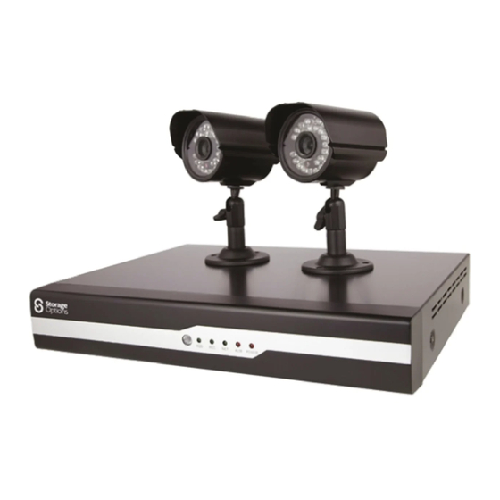
Summary of Contents for Storage Options Home CCTV Kit
- Page 2 CAUTION RISK OF ELECTRIC SHOCK DO NOT OPEN TO REDUCE THE RISK OF ELECTRIC SHOCK, DO NOT REMOVE THE COVER. NO USER SERVICABLE PARTS INSIDE. REFER SERVICING TO QUALIFIED PERSONNEL. The lightning flash with arrowhead symbol, within an equilateral triangle, is intended to alert the user to the presence of non- insulated “dangerous voltage”...
-
Page 3: Warranty And Technical Support
IMPORTANT SAFEGUARD All lead-free products offered by the company comply with the requirements of the European law of the Restriction of Hazardous Substances (RoHS) directive, which means our manufacturing processes and products are strictly “lead-free” and without the hazardous substances cited in the directive. The crossed-out wheeled bin mark symbolizes that within the European Union the product must be collected separately at the product’s end-of-life. -
Page 4: Table Of Contents
TABLE OF CONTENTS QUICK START GUIDE 1.1 – Basic Connectivity 1.2 – Wall Mounting A Camera 1.3 – Power Connection Diagram OVERVIEW 2.1 – System Overview 2.2 – Environment Adaptability 2.3 – Recording Capacities CONVENTIONS USED IN THIS MANUAL PACKAGE CONTENTS SYSTEM CONNECTION 5.1 –... - Page 5 TABLE OF CONTENTS (CONTINUED) ADVANCED MENU FUNCTIONS 8.1 – Advanced Setup 8.2 – Alarm 8.3 – E-Mail Setup 8.4 – System Info 8.5 – Motion Detection 8.6 – Mobile 8.7 – System 8.8 – Firmware Upgrade 8.9 – Parameter Export 8.10 –...
-
Page 6: Quick Start Guide
QUICK START GUIDE 1.1 – BASIC CONNECTIVITY To get started quickly with the Storage Options 2 Channel CCTV DVR, follow these instructions: 1. Connect a camera to the “Video In 1” socket. 2. Connect a computer monitor to the “VGA” socket. -
Page 7: Wall Mounting A Camera
1.2 – WALL MOUNTING A CAMERA Each Storage Options camera is supplied with a mounting kit for attaching it to a wall. Before you affix the camera in position, please ensure the cable is of adequate length to reach the DVR. -
Page 8: Power Connection Diagram
Connect the black cables to the two included cameras. Each Storage Options CCTV camera (sold separately) also comes with its own mains adapter. You can either plug them into separate mains sockets, or into the two spare cables on the power splitter. -
Page 9: Overview
2.1 – SYSTEM OVERVIEW Installing this DIY Home CCTV Kit could be one of the best steps you ever take to secure your home or business premises. As well as protecting against criminal activity and actively deterring criminals from targeting your property and vehicles, it will bring additional peace of mind for you and your family. -
Page 10: Conventions Used In This Manual
CONVENTIONS USED IN THIS MANUAL At various points in this manual you will see highlighted text. Please refer here for an explanation: NOTE Important notes are highlighted in blue. Tips on best practice are highlighted in green. CAUTION Important cautions and warnings are highlighted in red. Unless otherwise stated, all functionality described in this manual is performed using the USB mouse. -
Page 11: System Connection
SYSTEM CONNECTION 5.1 – CONNECTIVITY DIAGRAM Refer to this diagram for the recommended method of connecting this CCTV system. Refer to section “1.3 – Power Connection Diagram” (page 8) for more information on connecting to a mains socket. Page 11... -
Page 12: Basic Operation
BASIC OPERATION 6.1 – FRONT PANEL 1. IR SENSOR: Receives infra-red signals from the remote control. Do not cover. 2. LED INDICATORS: Shows system status. LABEL COLOUR DESCRIPTION GREEN Flashes to indicate HDD activity. GREEN Indicates whether the DVR is currently recording. GREEN Flashes to indicate network traffic. -
Page 13: Rear Panel
6.2 – REAR PANEL Refer to the diagram and table below for information on the DVR’s various connections. REFERENCE PHYSICAL CONNECTOR DESCRIPTION POWER input DC 12V / 3A VGA output Connect to a monitor with VGA (D-Sub) input RJ45 Connect to a computer network USB ports For USB flash drive (top) and mouse (bottom) RS485... -
Page 14: Remote Control
6.3 – REMOTE CONTROL The remote control can be used for navigating system menus. When using the remote control, the OK key performs the same functions as left-clicking the mouse. To use the remote control with the DVR system: 1. Insert 2x AAA 1.5V alkaline batteries (not included) into the back of the remote control. Please ensure correct orientation. -
Page 15: Mouse Control
6.4 – MOUSE CONTROL The mouse can be used for navigating system menus. NOTE Unless otherwise stated, all system functions described in this manual are achieved through mouse input. To use a mouse with the DVR system: Connect the mouse to the lower USB port located on the rear panel (labelled with a mouse icon). Click to select a menu option. -
Page 16: Power On / Off
6.6 – POWER ON / OFF To power the system on, connect the power cable to the DC 12V port on the rear panel. At start-up, the DVR performs a basic system check and runs an initial loading sequence. After a few moments, it will load a live display view. -
Page 17: Playback
6.10 – PLAYBACK The Search Menu can be used to view previously recorded footage. To begin playback: 1. Right-click anywhere on screen and select VIDEO SEARCH from the sub menu. NOTE When the Search Menu is first opened, it displays the current month and date. 2. -
Page 18: Basic Menu Functions
BASIC MENU FUNCTIONS 7.1 – MAIN MENU The main menu displays options for controlling every feature of the DVR. See below for an explanation of each of the options on the main menu. RECORD SEARCH: Search for previously recorded video on the system. ... -
Page 19: Search
7.2 – SEARCH Use this function to search for and play back previously recorded video on the DVR system. When the Search menu is opened for the first time, it will display the current date and time. To perform a quick search, simply open the SEARCH menu and click PLAY. The last 60 seconds of recorded playback will begin. -
Page 20: File List
7.3 – FILE LIST Use the File List sub menu to see a detailed list of all the recorded video on your system. To open the file list: 1. From the Search menu, click SEARCH to find recorded video. 2. Select FILE LIST at the bottom of the menu. The File List menu will open. 3. -
Page 21: Backup
7.4 – BACKUP Use the File List sub menu to find recorded video on your system and copy it to a USB flash drive (not included). NOTE The system is compatible with most major brands of USB flash drives, with capacities from 256MB to 4GB. To back up recorded data: 1. -
Page 22: Record Mode
7.5 – RECORD MODE Use this page to configure recording parameters and enable / disable audio. NOTE Audio capable cameras (not included) are required for audio recording. To configure recording options: 1. Under CHANNEL, use the drop-down menus and select ON / OFF to enable / disable recording from the selected channel. - Page 23 7.5 – RECORD MODE (CONTINUED) 1. Under FRAMERATE, it is possible to adjust in one frame per second increments. 2. Under AUDIO, select ON or OFF. If audio recording is enabled, the system will record audio from any connected audio-capable cameras (not included). 3.
-
Page 24: Recording Schedule
7.6 – RECORDING SCHEDULE By default, the system is configured to record continuously, but it is possible to set it to record by customisable recording schedule instead. The Schedule Grid shows the days of the week and hours 0-23. You can set alarm recording (red), general recording (green) or no recording (blue) to each time block of each day. -
Page 25: Hdd Management
7.7 – HDD MANAGEMENT This page displays essential information about the system’s internal hard drive, and lets you format the HDD or a USB flash drive (not included). The system will display “OK” if the HDD is operating correctly, or “No HDD STATUS: Disk”... -
Page 26: Basic Setup
7.8 – BASIC SETUP Use this page to set the system language, date and time, pass codes, and configure audio / video and display options. The Basic Setup menu contains the following sub menus: Language Date / Time ... -
Page 27: Date / Time
7.10 – DATE / TIME It is highly recommended to set the date and time immediately when first setting up the system. To set the date and time: 1. Click DATE / TIME and configure the following options: DATE: Enter the day, month, and year ... -
Page 28: Password
7.12 – PASSWORD The password page allows configuration of up to 6 accounts (1 admin, 5 normal users). The DEVICE ID is a unique numerical identifier (in the case that multiple DVRs are being used in one location). For each user, the following settings are available: 1. -
Page 29: User Permissions
7.13 – USER PERMISSIONS Click PERMISSION on the User Password Setup screen to open the User Permission menu. Here it is possible to choose what the selected user has access to. NOTE This page can only be adjusted by an admin account. Users can see but not change their permissions. NEXT: Continue to the next page of permissions. -
Page 30: Display
7.14 – DISPLAY Use the display setup menu to customise channel names, show / hide the date and time in live view and playback modes, and enable / disable preview channels. NAME: Enter a new title for the selected channel using the virtual keyboard. POSITION: Reposition the channel title. -
Page 31: Live
7.15 – LIVE Preview channels can be very useful if your display monitor is in public view. 1. Choose a channel you wish to conceal. Under LIVE, select OFF. 2. Click APPLY to save changes. The selected channel will turn black (but what the camera sees will still record). 3. -
Page 32: Advanced Menu Functions
ADVANCED MENU FUNCTIONS 8.1 – ADVANCED SETUP Use the Advanced Setup menu to configure alarm settings, motion detection, mobile surveillance, PTZ settings and network settings. The Advanced Setup menu contains the following sub-menus: Alarm Info Motion Detection (MD) ... -
Page 33: Alarm
8.2 – ALARM The Alarm menu can be used to configure alarm and e-mail settings. External alarm devices must be connected to the alarm block on the rear panel of the DVR in order to use NOTE the I/O alarms of the system. To configure alarm settings: 1. -
Page 34: E-Mail Setup
8.3 – E-MAIL SETUP The DVR can send an e-mail notification with a JPEG (single frame) snapshot for triggered events. To set up e-mail notification: 1. Under EMAIL, select ON. 2. Under SSL, select OFF. NOTE SSL deals with encryption. Only advanced users should enable this option. 3. -
Page 35: System Info
8.4 – SYSTEM INFO This page shows system information, including the firmware version, MAC address, and system serial number. There are no user-configurable settings on this page. 8.5 – MOTION DETECTION Each channel can be configured to record based on motion being detected in the frame. To configure motion detection: 1. -
Page 36: Mobile
8.6 – MOBILE It is possible to view footage from the DVR on your smart phone. When using the mobile viewer application “MEye”, please ensure that the “Mobile Port” setting matches the port number on this page. To configure notification settings: 1. -
Page 37: System
8.7 – SYSTEM Use the System menu to update system firmware and set an automatic system reset schedule. To enable auto-reset: 1. Under AUTO RESET, select ON. The Settings option will appear. 2. Under SETTINGS, select EVERY DAY, EVERY WEEK or EVERY MONTH. The Date drop-down menu will appear. 3. -
Page 38: Firmware Upgrade
8.8 – FIRMWARE UPGRADE Occasionally a new firmware update may be issued for this DVR. Please check the Storage Options website for more information. To upgrade firmware: 1. Copy the firmware file to an empty USB flash drive. The firmware file should be stored in the root of the drive. -
Page 39: Pan Tilt Zoom (Ptz)
8.11 – PAN TILT ZOOM (PTZ) Use the PTZ Setup menu to configure settings for a connected PTZ camera (not included). Consult the instruction manual of your PTZ camera for information about your camera, including protocol NOTE and baud rate. To configure a PTZ camera: 1. -
Page 40: Network
8.12 – NETWORK Use the Network Setup menu to configure network and DNS settings. NOTE Your router must support UPnP functionality. To configure network settings: 1. Under TYPE, select DHCP, PPPoE or STATIC (if unsure, choose DHCP as this is the most common). ... -
Page 41: Ddns
8.13 – DDNS A DDNS account allows you to set up a web site address that points back to your local network. A Web site address is easier to remember than a WAN IP. You must register an account with a DDNS service provider prior to configuring DDNS settings on the DVR. NOTE Visit http://www.dyndns.com... -
Page 42: Upnp
8.14 – UPNP The UPnP Forum is an industry initiative designed to enable simple and robust connectivity among consumer electronics, intelligent appliances and mobile devices from many different vendors. As a group, they are dedicated to making the “connected home and lifestyle” mainstream experiences for consumers. To configure UPnP settings: 1. -
Page 43: Remote Surveillance Software
REMOTE SURVEILLANCE SOFTWARE The DVR features built-in browser based software which allows access to the system locally over the Local Area Network (LAN) or remotely over the Internet, using Internet Explorer. Open Internet Explorer and type the DVR’s IP address into the address bar, then press Enter to load the page. On first use, you will be prompted to install ActiveX controls. -
Page 44: Using Remote Surveillance
9.1 – USING REMOTE SURVEILLANCE With your DVR connected to your Local Area Network (LAN), you can log in to the system using Internet Explorer browser. NOTE The DVR must be connected to your local or wide area network before attempting remote access. To Log Into The System: 1. -
Page 45: Main Screen
9.2 – MAIN SCREEN Once logged in, the Remote Surveillance main screen appears in the browser. REFERENCE ITEM DESCRIPTION Modes Choose from LIVE (default view), REPLAY and SETUP. Main Screen Main display screen for live viewing and playback. Time Stamp Time and date for each channel. -
Page 46: Live View
9.3 – LIVE VIEW By default, the browser-based remote surveillance system opens in Live View mode (split-screen). To use Live View: 1. Click LIVE at the top of the main screen. 2. Click the display mode icons to view the main screen in single-channel, quad or split-screen configurations. You can also double-click a channel at any time to view it in single-channel mode. -
Page 47: Ptz Control
9.6 – PTZ CONTROL You must have a PTZ camera (not included) connected to the system in order to use the PTZ controls. To control a PTZ camera: 1. Select the channel of the connected PTZ camera. 2. Click the ← or → navigation arrows to pan, and ↑ or ↓ keys to tilt the camera. 3. -
Page 48: Playback
9.8 – PLAYBACK Use the Replay menu to search and play back recorded video on the system. To use the replay menu: 1. Click REPLAY at the top of the main screen. The main screen will be grey. 2. Click REFRESH below the calendar to view the recorded files for the current month. Normal recording is indicated by a clock icon;... -
Page 49: Search
9.9 – SEARCH Use the calendar and drop-down menus to search for recorded video on your system. 1. Click < or > to change the month on the calendar. Dates with recorded video data will appear in bold. 2. Click the date. Recorded video files will populate the File List. 3. -
Page 50: Remote Setup
9.11 – REMOTE SETUP Use the Setup tab to configure the settings of your system from a remote location. If the Main Menu is open on the DVR system, you will not be able to make changes to settings from a Web NOTE browser. -
Page 51: Alarm Setting
9.13 – ALARM SETTING Click ALARM to access the setup interface and check or change settings in a similar manner to using the DVR’s GUI. 9.14 – PTZ Click PTZ to access the setup interface and check or change settings in a similar manner to using the DVR’s GUI. Page 51... -
Page 52: Network
9.15 – NETWORK Click NETWORK to access the setup interface and check or change settings in a similar manner to using the DVR’s GUI. 9.16 – SETTING Click SETTING to access the setup interface and check or change settings in a similar manner to using the DVR’s GUI. Page 52... -
Page 53: Maintenance
9.17 – MAINTENANCE Click MAINTENANCE to access the system configuration interface. Here you can remotely reboot the DVR, format it’s HDD, or upgrade the system’s firmware. 9.18 – HOST INFO Click HOST INFO to access the system information interface. The interface includes information on the HDD status, remaining record time, firmware version and network MAC address. -
Page 54: Software Cd
To convert these files to AVI format for use in other video playback software, please use the conversion tool included with “Playback”. Please be advised, third party mobile phone apps are provided as a convenience only, and Storage Options cannot provide support on their functionality. -
Page 55: Remote Access
80 on your device to a different number (such as 81 or 82), then creating the port forwarding rule to match. To correctly configure remote access to your new product, we recommend you follow the “Storage Options Remote Access Guide”, which is available as a downloadable PDF from http://www.storageoptions.com/support/. -
Page 56: Hard Disk Drive Installation
HARD DISK DRIVE INSTALLATION If you are at all hesitant to perform the following procedure, please refer to qualified service personnel. Follow these steps to install a HDD: When working with electrostatic sensitive devices such as a Hard Disk Drive (HDD) or DVR unit, make CAUTION sure you use a static-free workstation. -
Page 57: Troubleshooting
TROUBLESHOOTING If a solution to your problem is not listed below, please call our technical support team (see below). PROBLEM POSSIBLE CAUSES SOLUTIONS System is not receiving power, or Cable from power adapter is loose or Confirm that all cables are connected correctly. ... -
Page 58: Product Specification
PRODUCT SPECIFICATION DIY Home CCTV Kit Digital Video Recorder (DVR) Cameras Video Compression: H.264 Image: 1/3” CMOS Audio Compression: ADPCM Video System: PAL / NTSC Video Input: 4 channel (BNC) PAL Output: 720H x 576V Video Output: 1 channel (BNC) - Page 59 NOTES Page 59...
- Page 60 Page 60...
Need help?
Do you have a question about the Home CCTV Kit and is the answer not in the manual?
Questions and answers