Panasonic WH-SHF09D3E5 Service Manual
Air to water heat pump, indoor/ outdoor unit
Hide thumbs
Also See for WH-SHF09D3E5:
- Operating instructions manual (92 pages) ,
- Design handbook (132 pages)
Table of Contents
Advertisement
Quick Links
This service information is designed for experienced repair technicians only and is not designed for use by the general public.
It does not contain warnings or cautions to advise non-technical individuals of potential dangers in attempting to service a product.
Products powered by electricity should be serviced or repaired only by experienced professional technicians. Any attempt to
service or repair the product or products dealt with in this service information by anyone else could result in serious injury or death.
In order to avoid frostbite, be assured of no refrigerant leakage during the installation or repairing of refrigerant circuit.
WH-SHF09D3E5
WH-SHF12D6E5
WARNING
PRECAUTION OF LOW TEMPERATURE
Indoor Unit
© Panasonic Appliances Air-Conditioning (M) Sdn. Bhd. 2012.
Unauthorized copying and distribution is a violation of law.
Order No. PHAAM1201104C2
Outdoor Unit
WH-UH09DE5
WH-UH12DE5
Advertisement
Table of Contents

Related Manuals for Panasonic WH-SHF09D3E5


Summary of Contents for Panasonic WH-SHF09D3E5
- Page 1 PRECAUTION OF LOW TEMPERATURE In order to avoid frostbite, be assured of no refrigerant leakage during the installation or repairing of refrigerant circuit. © Panasonic Appliances Air-Conditioning (M) Sdn. Bhd. 2012. Unauthorized copying and distribution is a violation of law.
-
Page 2: Table Of Contents
19. Exploded View and Replacement Parts List ..............108 12.1 Basic Function ..........40 12.2 Water Pump ..........46 19.1 WH-SHF09D3E5 WH-SHF12D6E5 ..108 12.3 Pump Down Operation ........47 19.2 WH-UH09DE5 WH-UH12DE5 ....110 12.4 Flow Switch..........47 12.5 Force Heater Mode Operation .....47 12.6 Indoor Unit Safety ........48... -
Page 3: Safety Precautions
1. Safety Precautions Read the following “SAFETY PRECAUTIONS” carefully before perform any servicing. Electrical work must be installed or serviced by a licensed electrician. Be sure to use the correct rating and main circuit for the model installed. The caution items stated here must be followed because these important contents are related to safety. The meaning of each indication used is as below. - Page 4 19. Install according to this installation instructions strictly. If installation is defective, it will cause water leakage, electrical shock or fire. 20. Install at a strong and firm location which is able to withstand the set’s weight. If the strength is not enough or installation is not properly done, the set will drop and cause injury.
-
Page 5: Specifications
2. Specifications WH-SHF09D3E5 WH-UH09DE5 Item Unit Outdoor Unit Performance Test Condition EN14511 Condition A7W35 A2W35 (Ambient/Water) 9.00 9.00 Heating Capacity BTU/h 30700 30700 kcal/h 7740 7740 4.55 3.40 kcal/hW 3.91 2.92 dB (A) Noise Level Power Level dB Air Flow... - Page 6 Item Unit Running Current 12.7 Maximum Current For Heat Pump System 28.5 Power Factor Power factor means total figure of compressor and outdoor fan motor. Number of core Power Cord Length m (ft) Thermostat Electronic Control Protection Device Electronic Control Item Unit Indoor Unit...
-
Page 7: Wh-Shf12D6E5 Wh-Uh12De5
WH-SHF12D6E5 WH-UH12DE5 Item Unit Outdoor Unit Performance Test Condition EN14511 Condition A7W35 A2W35 (Ambient/Water) 12.00 12.00 Heating Capacity BTU/h 41000 41000 kcal/h 10320 10320 4.40 3.23 kcal/hW 3.78 2.77 dB (A) Noise Level Power Level dB Air Flow /min (ft /min) 80.0 (2830) Refrigeration Control Device... - Page 8 Item Unit Running Current 13.0 17.4 Maximum Current For Heat Pump System 29.0 Power Factor Power factor means total figure of compressor and outdoor fan motor. Number of core Power Cord Length m (ft) Thermostat Electronic Control Protection Device Electronic Control Item Unit Indoor Unit...
-
Page 9: Features
3. Features Inverter Technology - Energy saving High Efficiency Compact Design Environment Protection - Non-ozone depletion substances refrigerant (R407C) Long Installation Piping - Long piping up to 30 meter with height difference 20 meter - Flexible 4-way piping for outdoor unit Easy to use control panel Weekly Timer setting Quality Improvement... -
Page 10: Location Of Controls And Components
4. Location of Controls and Components Indoor Unit 4.1.1 Location of Control... - Page 13 4.1.2 Weekly Timer Setting...
- Page 14 4.1.3 Setting Up the Special Functions...
-
Page 15: Outdoor Unit
4.1.4 Main Components Outdoor Unit... -
Page 16: Dimensions
5. Dimensions Indoor Unit... -
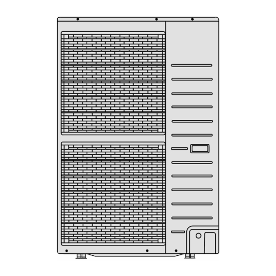
Page 17: Outdoor Unit
Outdoor Unit... -
Page 18: Refrigeration And Water Cycle Diagram
6. Refrigeration and Water Cycle Diagram Piping size Min. Max. Rated Common Additional Piping Piping Model Length Length Elevation Refrigerant Liquid Length Length (g/m) UH09DE5 5/8” 3/8” UH12DE5 5/8” 3/8” * If piping length is over common length, additional refrigerant should be added as shown in the table. -
Page 20: Block Diagram
7. Block Diagram... -
Page 21: Wiring Connection Diagram
8. Wiring Connection Diagram Indoor Unit 8.1.1 WH-SHF09D3E5... - Page 22 8.1.2 WH-SHF12D6E5...
-
Page 23: Outdoor Unit
Outdoor Unit... -
Page 24: Electronic Circuit Diagram
9. Electronic Circuit Diagram Indoor Unit 9.1.1 WH-SHF09D3E5... - Page 25 9.1.2 WH-SHF12D6E5...
-
Page 26: Outdoor Unit
Outdoor Unit... -
Page 27: Printed Circuit Board
10. Printed Circuit Board 10.1 Indoor Unit 10.1.1 Main Printed Circuit Board... - Page 28 10.1.2 Solar Printed Circuit Board (Optional)
-
Page 29: Outdoor Unit
10.2 Outdoor Unit 10.2.1 Main Printed Circuit Board... - Page 30 10.2.2 Capacitor Printed Circuit Board 10.2.3 Noise Filter Printed Circuit Board...
-
Page 31: Installation Instruction
11. Installation Instruction 11.1 Select the Best Location Indoor Unit Piping size Addi- Min. Max. There should not be any heat source or steam Rated tional Eleva- Piping Piping Model Length Refrige- near the unit. tion Length Length Gas Liquid rant A place where air circulation in the room is good. -
Page 32: Indoor Unit
11.3 Indoor Unit 11.3.1 How to Fix Installation Plate 11.3.3 Indoor Unit Installation The mounting wall is strong and solid enough to prevent it from vibration. 11.3.3.1 Install the Indoor Unit When connecting solar pump station cable between indoor unit and solar pump station, the distance between both apparatuses shall be 2 ~ 8 meters and the length of the said cable must be shorter than 10 meter. - Page 33 11.3.3.3 Indoor Unit Refrigerant Pipe Install external filter (30 mesh or more, field supply) before water inlet of indoor unit (with “WATER IN” Installation indication). Please make flare after inserting flare nut Refer to Diagram 4.1 for pipe connection of Panel (located at joint portion of tube assembly) onto Heater, Floor Heater, Tank Unit, Solar Pump the copper pipe.
-
Page 34: Connect The Cable To The Indoor Unit
11.3.4 Connect the Cable to the Indoor Unit Connecting cable between indoor unit and outdoor unit shall be approved polychloroprene sheathed 4 x 4.0 or 6.0 mm flexible cord, type designation 60245 IEC 57 or heavier cord. Ensure the colour of wires of outdoor unit and the terminal Nos. are the same to the indoor unit’s respectively. - Page 35 Terminal screw Tightening torque N•cm {kgf•cm} 157~196 {16~20} 196~245 {20~25} 11.3.4.1 Wire Stripping and Connecting Requirement...
- Page 36 11.3.4.2 Connecting Requirement The equipment’s power supply 1 complies with IEC/EN 61000-3-12 provided that the short-circuit power S greater than or equal to 1700.31kW (for SHF09D3E5/UH09DE5 and SHF12D6E5/UH12DE5) at the interface point between the user’s supply and the public system. It is the responsibility of the installer or user of the equipment to ensure, by consultation with the distribution network operator if necessary, that the equipment is connected only to a supply with a short-circuit power S greater than or equal to 1700.31kW.
-
Page 37: Outdoor Unit
11.4 Outdoor Unit 11.4.1 Install the Outdoor Unit After selecting the best location, start installation according to Indoor/Outdoor Unit Installation Diagram. Fix the unit on concrete or rigid frame firmly and horizontally by bolt nut (ø10mm). When installing at roof, please consider strong wind and earthquake. -
Page 38: Connect The Cable To The Outdoor Unit
11.4.3 Evacuation of the Equipment WHEN INSTALLING AN AIR-TO-WATER HEATPUMP, BE SURE TO EVACUATE THE AIR INSIDE THE INDOOR UNIT AND PIPES in the following procedure. Connect a charging hose with a push pin to the Low side of a charging set and the service port of the 3-way valve. -
Page 39: Pipe Insulation
Select required direction and apply protective bushing provided in accessories to protect cables from sharp edges. Once all wiring work has been completed, tie the cables and cord together with the binding strap so that they do not touch other parts such as the compressor and bare copper pipes. Install back the control board cover. -
Page 40: Operation And Control
12. Operation and Control 12.1 Basic Function Inverter control, which equipped with a microcomputer in determining the most suitable operating mode as time passes, automatically adjusts output power for maximum comfort always. In order to achieve the suitable operating mode, the microcomputer maintains the set temperature by measuring the temperature of the environment and performing temperature shifting. - Page 41 Booster heater control - Booster heater turn On and Off follow normal operation. - Booster heater turn ON condition: During startup time (initialization), Booster heater turn ON after DELAY TIMER. When tank temperature lower than HEATER ON TEMP 20 minutes from previous heater off. - Booster heater turn OFF condition: When tank temperature higher than tank set temperature for continuous 15 secs.
- Page 42 Case 2: Heat pump THERMO OFF TEMP: Heat pump THERMO OFF TEMP = 63°C + [+4°C]. Water outlet temperature > Heat pump THERMO OFF TEMP for continuous 3 minutes, heat pump OFF. Next THERMO ON TEMP: THERMO ON TEMP = Water inlet when heat pump THERMO OFF + [-3°C]. If water outlet temperature <...
- Page 43 - Switch to tank heat-up interval and start counting tank heat-up timer when tank temperature < THERMO ON TEMP after room heat-up interval timer complete * THERMO ON TEMP is defined form following Case1 to Case4. During tank heat-up interval - Heat pump tank target temperature = Tank set temperature or [60°C] whichever lower - Heat pump Water Outlet set temperature is set to Maximum [65°C] during tank interval - Initial Tank THERMO ON TEMP = heat pump tank target temperature + [-2°C]...
- Page 44 Solar 3 way valve: Solar 3WV operates follow solar operation specification. * Under solar priority is set condition, when solar 3WV is ON, booster heater turn OFF * Under solar priority is not set condition, solar 3WV only can ON during heating heat-up interval. 2 way valve opens.
- Page 45 12.1.7 Outdoor Fan Motor Operation Outdoor fan motor is adjusted according to operation condition. It starts when compressor starts operation and it stops 30 seconds after compressor stops operation.
-
Page 46: Water Pump
12.2 Water Pump 12.2.1 Water Pump Control Once the indoor unit is ON, the water pump will be ON immediately and no error judgement for 9 minutes. However, during this 9 minutes operation, if there is any abnormality cause at outdoor or malfunction, the compressor should be OFF immediately and restart delay after 3 minutes. -
Page 47: Pump Down Operation
12.3 Pump Down Operation Purpose Ensure the pump down operation when relocating or disposing of the unit. The pump down operation will extract all refrigerant from the piping into the outdoor unit. Pump down operation control: Press the SERVICE S/W for continuous 5 secs to enter Service mode. In service mode, select Sr:01 and press SET S/W to start Pump Down operation. -
Page 48: Indoor Unit Safety
12.6 Indoor Unit Safety 12.6.1 Indoor Unit Safety Control When water pump is ON, the system will start checking flow switch status (ON/OFF). If the flow switch ON for 10 seconds, the system will check on the water inlet temperature for 10 seconds. If the water inlet temperature not exceeds 80°C, the water pump shall be continuously running with normal mode. -
Page 49: Indoor Back-Up Heater Control
12.9 Indoor Back-Up Heater Control 12.9.1 Indoor Electric Heater Control Normal Heating Mode Heater On condition: a. Heater switch is ON b. After Heatpump thermo ON for [30] mins c. After water pump operate [9] mins d. Outdoor air temperature < Outdoor set temperature for heater e. -
Page 50: Tank Booster Heater Control
12.10 Tank Booster Heater Control 12.10.1 Tank Booster Heater Control Heating operation condition: Booster heater Turn On condition: After BOOSTER HEATER DELAY TIMER fulfill during heat pump startup time in tank mode, or during switching from heating heat-up interval to tank heat-up interval in heat + tank mode (heating priority not set). -
Page 51: Quiet Operation
12.13 Quiet Operation Purpose: - To provide quiet operation compare to normal operation by reduces outdoor unit noise. Starting condition: When quiet button is presses. When quiet request ON time by weekly timer (Refer to control panel.) When any of above mentioned condition is achieved, this control is activated. New target FM speed = Present target FM speed - 80 rpm Minimum target FM speed = 200 rpm Cancellation condition:... - Page 52 When solar priority is NOT SET Operation condition: Solar pump operates if all of the following conditions are fulfilled: Power On. (regardless operation ON or OFF). There is operation request from solar pump station. Tank hot water temp is below solar on upper limit temp 80°C. Heat pump thermo OFF in tank mode OR Heat pump operate to room side (during operation ON and tank mode selected).
-
Page 54: External Room Thermostat Control (Optional)
12.15 External Room Thermostat Control (Optional) Purpose: Better room temperature control to fulfill different temperature request by external room thermostat. Recommended external room thermostat: Maker Characteristic Siemen (REV200) Touch panel Siemen (RAA20) Analog Connection external room thermostat: Wire Connection and thermo characteristic of Siemen REV200: Setting L/L1 (H) Heat Thermo... -
Page 55: Protection Control
13. Protection Control 13.1 Protection Control for All Operations 13.1.1 Time Delay Safety Control The compressor will not start for three minutes after stop of operation. 13.1.2 30 Seconds Forced Operation Once the compressor starts operation, it will not stop its operation for 30 seconds. However, it can be stopped using control panel at indoor unit. -
Page 56: Low Pressure Protection Control
13.1.6 Low Pressure Protection Control Purpose: To protect the system operation. Detection period: After compressor on for 5 minutes. Detection conditions: When detection of Tem above 30°C. Calculation of average evaporation temperature (Tem). Use outdoor low pressure sensor. Tem use the value calculated for discharge temperature setting value After detection: Compressor stops restart again after 3 mins. -
Page 57: Protection Control For Heating Operation
13.1.10 Crank Case Heater Control Purpose: - For compressor protection during low outdoor ambient operation (during heating low temperature operation). Control content: a. Trigger heater START condition When the outdoor air temperature is 13°C or below, and discharge temperature is 13.2°C or below. b. -
Page 58: Servicing Mode
14. Servicing Mode 14.1 How to Take Out Front Plate Please follow the steps below for take out front plate. Before removing the front plate of indoor unit, always switch off all power supply (i.e. indoor unit power supply, heater power supply and tank unit power supply). Remove the 2 mounting screws which located at bottom of the front plate and 1 mounting screw at the front of the plate. -
Page 59: How To Adjust Water Flow Rate
14.5 How to Adjust Water Flow Rate Before adjust the water flow rate, make sure that the total water volume in the installation is 50 litres minimum. The water flow rate can be adjusted with select the water pump speed on the water pump. The default setting is moderate speed (II). -
Page 60: Maintenance Guide
15. Maintenance Guide In order to ensure optimal performance of the unit, checks and inspections on the unit and the field wiring must be carried out regularly. Before carried out any maintenance or repair work, and removing the front plate of heat exchanger unit, always switch off all power supply (i.e. - Page 61 Reset overload protector Overload protector serves the safety purpose to prevent the water over heating. When the overload protector trip at high water temperature, take below steps to reset it. a. Take out OLP cover. b. Use a test pen to push the centre button gently in order to reset the Overload protector. c.
-
Page 62: Troubleshooting Guide
16. Troubleshooting Guide 16.1 Refrigeration Cycle System In order to diagnose malfunctions, make sure that there are no electrical problems before inspecting the refrigeration cycle. Such problems include insufficient insulation, problem with the power source, malfunction of a compressor and a fan. -
Page 63: Relationship Between The Condition Of The Air-To-Water Heatpump Indoor And Outdoor Units And Pressure And Electric Current
16.2 Relationship between the Condition of the Air-to-Water Heatpump Indoor and Outdoor Units and Pressure and Electric Current Heating Mode Condition of the Air-to-Water Heatpump indoor and outdoor Low Pressure High Pressure Electric current during operation units Water leakage or insufficient water flow rate in the system Excessive amount of refrigerant Inefficient compression... -
Page 64: Breakdown Self Diagnosis Function
16.3 Breakdown Self Diagnosis Function 16.3.1 Self Diagnosis Function (Three Digits Alphanumeric Code) When abnormality occur during operation, the system will stop operation, and OFF/ON control panel LED will blink and error code will display on the control panel timer display LCD. Even error code is reset by turning OFF power supply or by pressing ERROR RESET button, if the system abnormality is still un-repaired, system will again stop operation, and OFF/ON control panel LED will again blink. -
Page 65: Error Codes Table
16.4 Error Codes Table Diagnosis display Abnormality/Protection control Abnormality judgement Primary location to verify No abnormality detected — — Indoor/Outdoor capacity unmatched continue for 90 sec. Indoor/outdoor connection wire Indoor/outdoor PCB Specification and combination table in catalogue Outdoor compressor temperature sensor Continue for 90 sec. - Page 66 Diagnosis display Abnormality/Protection control Abnormality judgement Primary location to verify Outdoor defrost sensor abnormality Continue for 5 sec. Outdoor defrost sensor (defective or disconnected) Indoor water outlet temperature sensor Continue for 5 sec. Water outlet temperature sensor abnormality (defective or disconnected) Outdoor Current Transformer open —...
-
Page 67: Self-Diagnosis Method
16.5 Self-diagnosis Method 16.5.1 Connection Capability Rank Abnormality (H12) Malfunction Decision Conditions: During startup operation of heating, the capability rank of indoor checked by the outdoor is used to determine connection capability rank abnormality. Malfunction Caused: Wrong model interconnected. Wrong indoor unit or outdoor unit PCB (main) used. Faulty indoor unit or outdoor unit PCB (main). - Page 68 16.5.2 Compressor Tank Temperature Sensor Abnormality (H15) Malfunction Decision Conditions: During startup and operation of heating, the temperatures detected by the compressor tank temperature sensor are used to determine sensor error. Malfunction Caused: Faulty connector connection. Faulty sensor. Faulty outdoor unit PCB (main). Abnormality Judgment: Continue for 5 seconds.
- Page 69 16.5.3 Indoor Refrigerant Liquid Temperature Sensor Abnormality (H23) Malfunction Decision Conditions: During startup and operation of heating, the temperatures detected by the indoor refrigerant liquid temperature sensor are used to determine sensor error. Malfunction Caused: Faulty connector connection. Faulty sensor. Faulty indoor unit PCB (main).
-
Page 70: Compressor Low Pressure Protection (H)
16.5.4 Compressor Low Pressure Protection (H42) Malfunction Decision Conditions: During operation of heating and after 5 minutes compressor ON, when outdoor pipe temperature below -29°C or above 26°C is detected by the outdoor pipe temperature sensor. Malfunction Caused: Dust accumulation on the outdoor unit heat exchanger. Air short circuit at outdoor unit. - Page 71 16.5.5 Water Flow Switch Abnormality (H62) Malfunction Decision Conditions: During operation of heating, the water flow detected by the indoor water flow switch is used to determine water flow error. Malfunction Caused: Air trapped in water system. Faulty water pump. Water leak in system.
- Page 72 16.5.6 Outdoor Low Pressure Abnormality (H63) Malfunction Decision Conditions: During operation of heating, when the outdoor low pressure sensor output signal is 0Vdc or 5Vdc. Malfunction Caused: Faulty connector connection. Faulty sensor. Faulty outdoor unit PCB (main). Abnormality Judgment: Continue 4 times in 20 minutes.
- Page 73 16.5.7 Outdoor High Pressure Abnormality (H64) Malfunction Decision Conditions: During operation of heating, when the outdoor high pressure sensor output signal is 0Vdc or 5Vdc. Malfunction Caused: Faulty connector connection. Faulty sensor. Faulty outdoor unit PCB (main). Abnormality Judgment: Continue 4 times in 20 minutes.
- Page 74 16.5.8 Indoor Backup Heater OLP Abnormality (H70) Malfunction Decision Conditions: During operation of indoor backup heater, when no power supplies to indoor backup heater or OLP open circuit. Malfunction Caused: Faulty power supply connector connection. Faulty connector connection. Faulty indoor backup heater overload protector (OLP). Faulty indoor unit PCB (main).
- Page 75 16.5.9 Tank Temperature Sensor Abnormality (H72) Malfunction Decision Conditions: When tank connection is set to ON, the temperatures detected by the tank temperature sensor are used to determine sensor error. Malfunction Caused: Faulty connector connection. Faulty sensor. Faulty indoor unit PCB (main). Abnormality Judgment: Continue for 5 seconds.
- Page 76 16.5.10 Indoor-Control Panel Communication Abnormality (H76) Malfunction Decision Conditions: During standby and operation of heating, indoor-remote control error occur. Malfunction Caused: Faulty connector connection. Faulty remote control. Faulty indoor unit PCB (main).
- Page 77 16.5.11 Indoor/Outdoor Abnormal Communication (H90) Malfunction Decision Conditions: During operation of heating, the data received from outdoor unit in indoor unit signal transmission is checked whether it is normal. Malfunction Caused: Faulty outdoor unit PCB (main). Faulty indoor unit PCB (main). Indoor-outdoor signal transmission error due to wrong wiring.
- Page 78 16.5.12 Tank Booster Heater OLP Abnormality (H91) Malfunction Decision Conditions: During operation of tank booster heater, and tank booster heater OLP open circuit. Malfunction Caused: Faulty connector connection. Faulty tank booster heater overload protector (OLP). Faulty indoor unit PCB (main). Abnormality Judgment: Continue for 60 seconds.
- Page 79 16.5.13 Unspecified Voltage between Indoor and Outdoor (H95) Malfunction Decision Conditions: The supply power is detected for its requirement by the indoor/outdoor transmission. Malfunction Caused: Insufficient power supply. Faulty outdoor unit PCB (noise filter/main).
- Page 80 16.5.14 Outdoor High Pressure Protection (H98) Malfunction Decision Conditions: During operation of heating, when pressure 4.0 MPa and above is detected by outdoor high pressure sensor. Malfunction Caused: Faulty water pump. Insufficient water flow rate in system. Water leak in system. 3 way closed.
- Page 81 16.5.15 Indoor Freeze-up Protection (H99) Malfunction Decision Conditions: During anti-freezing control in cooling operation, when the indoor refrigerant liquid temperature < 0°C. Malfunction Caused: Faulty water pump. Insufficient water flow rate in system. Water leak in system. 2 way valve partially closed. Clogged expansion valve or strainer.
- Page 82 16.5.16 Outdoor High Pressure Switch Activate (F12) Malfunction Decision Conditions: During operation of heating, when pressure 4.5MPa and above is detected by outdoor high pressure switch. Malfunction Caused: Faulty water pump. Insufficient water flow rate in system. Water leak in system. 3 way valve closed.
- Page 83 16.5.17 Compressor Rotation Failure (F14) Malfunction Decision Conditions: A compressor rotation failure is detected by checking the compressor running condition through the position detection circuit. Malfunction Caused: Compressor terminal disconnect. Faulty outdoor unit PCB (main). Faulty compressor. Abnormality Judgment: Continue 4 times in 20 minutes.
- Page 84 16.5.18 Outdoor Fan Motor (DC Motor) Mechanism Locked (F15) Malfunction Decision Conditions: The rotation speed detected by the Hall IC of the fan motor during fan motor operation is used to determine abnormal fan motor (feedback of rotation > 2550rpm or < 50rpm). Malfunction Caused: Operation stop due to short circuit inside the fan motor winding.
- Page 85 16.5.19 Input Over Current Detection (F16) Malfunction Decision Conditions: During operation of heating, when outdoor current above 27.9A is detected by the current transformer (CT) in the outdoor unit PCB. Malfunction Caused: Excessive refrigerant. Faulty outdoor unit PCB (main). Abnormality Judgment: Continue 3 times in 20 minutes.
- Page 86 16.5.20 Compressor Overheating (F20) Malfunction Decision Conditions: During operation of heating, when temperature above 112°C is detected by the compressor tank temperature sensor. Malfunction Caused: Faulty compressor tank temperature sensor. 3 way valve closed. Refrigerant shortage (refrigerant leakage). Clogged expansion valve or strainer. Faulty outdoor unit PCB (main).
- Page 87 16.5.21 IPM Overheating (F22) Malfunction Decision Conditions: During operation of heating, when temperature 95°C is detected by the outdoor IPM temperature sensor. Malfunction Caused: Faulty outdoor unit fan motor. Faulty outdoor unit PCB (main). Abnormality Judgment: Continue 3 times in 30 minutes.
- Page 88 16.5.22 Output Over Current Detection (F23) Malfunction Decision Conditions: During operation of heating, when outdoor DC current is above 40.1 ± 5.0A (for: 6kW~9kW) OR 44.7 ± 5.0A (for: 12kW~16kW) is detected by the IPM DC Peak sensing circuitry in the outdoor unit PCB (main). Malfunction Caused: Faulty outdoor unit PCB (main).
- Page 89 16.5.23 Refrigeration Cycle Abnormality (F24) Malfunction Decision Conditions: During operation of heating, compressor frequency > Frated. During operation of heating, running current: 0.65A < I < 1.65A. During operation of heating, indoor refrigerant liquid temperature - water inlet temperature < 5°C. Malfunction Caused: Faulty water inlet or indoor refrigerant liquid temperature sensors.
- Page 90 16.5.24 Four Way Valve Abnormality (F25) Malfunction Decision Conditions: During heating operation, when the indoor pipe temperature of thermostat ON indoor unit < 0°C. Malfunction Caused: Faulty sensor. Faulty connector connection. Faulty outdoor unit PCB (noise filter/main). Faulty four way valve. Abnormality Judgment: Continue 4 times in 30 minutes.
- Page 91 16.5.25 Outdoor High Pressure Switch Abnormal (F27) Malfunction Decision Conditions: During compressor stop, and outdoor high pressure switch is remain opened. Malfunction Caused: Faulty connector connection. Faulty switch. Faulty outdoor unit PCB (main). Abnormality Judgment: Continue for 1 minute.
- Page 92 16.5.26 Outdoor Air Temperature Sensor Abnormality (F36) Malfunction Decision Conditions: During startup and operation of heating, the temperatures detected by the outdoor air temperature sensor are used to determine sensor error. Malfunction Caused: Faulty connector connection. Faulty sensor. Faulty outdoor unit PCB (main). Abnormality Judgment: Continue for 5 seconds.
- Page 93 16.5.27 Indoor Water Inlet Temperature Sensor Abnormality (F37) Malfunction Decision Conditions: During startup and operation of heating, the temperatures detected by the indoor water inlet temperature sensor are used to determine sensor error. Malfunction Caused: Faulty connector connection. Faulty sensor. Faulty indoor unit PCB (main).
- Page 94 16.5.28 Outdoor Discharge Pipe Temperature Sensor Abnormality (F40) Malfunction Decision Conditions: During startup and operation of heating, the temperatures detected by the outdoor discharge pipe temperature sensor are used to determine sensor error. Malfunction Caused: Faulty connector connection. Faulty sensor. Faulty outdoor unit PCB (main).
- Page 95 16.5.29 Power Factor Correction (PFC) Abnormality (F41) Malfunction Decision Conditions: During operation of heating, when the PFC protection circuitry in the outdoor unit PCB (main) senses abnormal high DC voltage level. Malfunction Caused: Power supply surge. Compressor windings not uniform. Faulty outdoor unit PCB (main).
- Page 96 16.5.30 Outdoor Pipe Temperature Sensor Abnormality (F42) Malfunction Decision Conditions: During startup and operation of heating, the temperatures detected by the outdoor pipe temperature sensor are used to determine sensor error. Malfunction Caused: Faulty connector connection. Faulty sensor. Faulty outdoor unit PCB (main). Abnormality Judgment: Continue for 5 seconds.
- Page 97 16.5.31 Outdoor Defrost Temperature Sensor Abnormality (F43) Malfunction Decision Conditions: During startup and operation of heating, the temperatures detected by the outdoor defrost temperature sensor are used to determine sensor error. Malfunction Caused: Faulty connector connection. Faulty sensor. Faulty outdoor unit PCB (main). Abnormality Judgment: Continue for 5 seconds.
- Page 98 16.5.32 Indoor Water Outlet Temperature Sensor Abnormality (F45) Malfunction Decision Conditions: During startup and operation of heating, the temperatures detected by the indoor water outlet temperature sensor are used to determine sensor errors. Malfunction Caused: Faulty connector connection. Faulty sensor. Faulty indoor unit PCB (main).
- Page 99 16.5.33 Outdoor Current Transformer Open Circuit (F46) Malfunction Decision Conditions: A current transformer (CT) open circuit is detected by checking the compressor running frequency (≥ rated frequency) and CT detected input current (< 0.65A) for continuously 20 seconds. Malfunction Caused: CT defective.
- Page 100 16.5.34 Cooling High Pressure Overload Protection (F95) Malfunction Decision Conditions: During operation of cooling, when pressure 4.0MPa and above is detected by outdoor high pressure sensor. Malfunction Caused: Dust accumulation in the outdoor unit heat exchanger. Air short circuit at outdoor unit. 2 way valve closed.
-
Page 101: Disassembly And Assembly Instructions
17. Disassembly and Assembly Instructions WARNING High Voltage are generated in the electrical parts area by the capacitor. Ensure that the capacitor has discharged sufficiently before proceeding with repair work. Failure to heed this caution may result in electric shocks. 17.1 To Remove Front Plate Please follow the steps below for take out front plate. -
Page 102: To Remove Pressure Gauge
17.3 To Remove Pressure Gauge 17.4 To Remove Control Panel... -
Page 103: To Remove Rccb/Elcb
17.5 To Remove RCCB/ELCB 17.6 To Remove Transformer and Electronic Controller Board... -
Page 104: To Remove Air Purge Valve, Pressure Relief Valve, Flow Switch, Water Pump And Bottle Complete
17.7 To Remove Air Purge Valve, Pressure Relief Valve, Flow Switch, Water Pump and Bottle Complete When reinstall the water pipe, use grease or water at the joining. - Page 105 When reinstall the water pipe, use grease or water at the joining. When reinstall the water pipe, use grease or water at the joining.
-
Page 106: Technical Data
18. Technical Data 18.1 Heating Capacity Table 18.1.1 WH-SHF09D3E5 WH-UH09DE5 Tamb 9000 3500 9000 3750 8900 4050 8800 4300 9000 3100 9000 3330 9000 3600 8900 3870 9000 2470 9000 2650 9000 2950 9000 3250 9000 1860 9000 1980 9000... -
Page 107: Heating Capacity At Different Piping Length
18.2 Heating Capacity at Different Piping Length WH-SHF09 WH-SHF12 Pipe Length 9000 1990 12000 2750 9000 1980 12000 2730 8000 1880 10300 2550 7400 1880 9500 2550 7000 1880 9000 2550 HC: Heating Capacity (kW) IP: Power Input (kW) Outdoor air temperature: 7°C (DBT), 6°C (WBT) Indoor water inlet temperature: 30°C Indoor water outlet temperature: 35°C Piping Length: 7m... -
Page 108: Exploded View And Replacement Parts List
19. Exploded View and Replacement Parts List 19.1 WH-SHF09D3E5 WH-SHF12D6E5 Note: The above exploded view is for the purpose of parts disassembly and replacement. The non-numbered parts are not kept as standard service parts. - Page 109 < Model: WH-SHF09D3E5 WH-SHF12D6E5> REF. NO. DESCRIPTION & NAME QTY. WH-SHF09D3E5 WH-SHF12D6E5 REMARKS BASE PAN CWD521266 ← HOT WATER COIL-COMPLETE CWB90C1035 ← RECEIVER CWB141039 ← FLOAT (FLOW SWITCH) CWB601008 ← TUBE CONNECTOR-COMPLETE CWT29C1043 ← FLARE NUT (5/8) CWT251061 ← FLARE NUT (7/8) CWT251064 ←...
-
Page 110: Wh-Uh09De5 Wh-Uh12De5
19.2 WH-UH09DE5 WH-UH12DE5... - Page 112 Note: The above exploded view is for the purpose of parts disassembly and replacement. The non-numbered parts are not kept as standard service parts.
- Page 113 < Model: WH-UH09DE5 WH-UH12DE5> REF. NO. DESCRIPTION & NAME QTY. WH-UH09DE5 WH-UH12DE5 REMARKS BASE PAN ASS’Y CWD52K1275 ← COMPRESSOR 4JD650XAA22 ← BUSHING - COMPRESSOR MOUNT CWH50055 ← NUT-COMPRESSOR MOUNT CWH561049 ← PACKING CWB811017 ← CRANKCASE HEATER CWA341053 ← CONDENSER COMPLETE CWB32C3494 ←...
- Page 114 REF. NO. DESCRIPTION & NAME QTY. WH-UH09DE5 WH-UH12DE5 REMARKS MAGNET RELAYS K6C1AYY00003 ← V-COIL COMPLETE - EXP. VALVE (BYPASS) CWA43C2335 ← SENSOR-COMP. TEMP COIL (BYPASS) CWA50C2797 ← ACCESSORY CO.(DRAIN ELBOW) CWG87C2030 ← Note: All parts are supplied from PAPAMY, Malaysia (Vendor Code: 00029488). “O”...
Need help?
Do you have a question about the WH-SHF09D3E5 and is the answer not in the manual?
Questions and answers