Table of Contents
Advertisement
www.proform.com
USER'S MANUAL
Model No. PFTL16011.0
Serial No.
Write the serial number in the space
above for reference.
Serial Number
Decal
QUESTIONS?
If you have questions, or if parts
are damaged or missing, DO NOT
CONTACT THE STORE; please
contact Customer Care.
IMPORTANT: Please register this
product (see the limited warranty
on the back cover of this manual)
before contacting Customer Care.
CALL TOLL-FREE:
1-888-533-1333
Mon.–Fri. 6 a.m.–6 p.m. MT
Sat. 8 a.m.–4 p.m. MT
ON THE WEB:
www.proformservice.com
CAUTION
Read all precautions and instruc-
tions in this manual before using
this equipment. Save this manual
for future reference.
Advertisement
Table of Contents

Related Manuals for ProForm PRO 4500


Summary of Contents for ProForm PRO 4500
- Page 1 USER’S MANUAL Model No. PFTL16011.0 Serial No. Write the serial number in the space above for reference. Serial Number Decal QUESTIONS? If you have questions, or if parts are damaged or missing, DO NOT CONTACT THE STORE; please contact Customer Care.
-
Page 2: Table Of Contents
Apply the decal in the location shown. Note: The decals may not be shown at actual size. One decal is located at the front of the treadmill. 310841 PROFORM is a registered trademark of ICON IP, Inc. -
Page 3: Important Precautions
16. To informed of all warnings and precautions. purchase a surge suppressor, see your local PROFORM dealer, call the telephone number 3. Use the treadmill only as described. on the front cover of this manual, or see your local electronics store. - Page 4 DANGER: 20. Never leave the treadmill unattended while Always unplug the power it is running. Always remove the key, unplug cord immediately after use, before clean- the power cord, and press the power switch ing the treadmill, and before performing the into the off position when the treadmill is not maintenance and adjustment procedures in use.
-
Page 5: Before You Begin
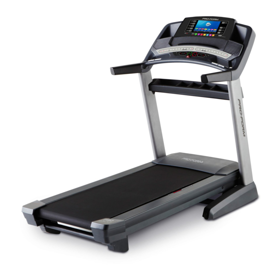
Thank you for selecting the revolutionary reading this manual, please see the front cover of this PROFORM PRO 4500 treadmill. The PRO 4500 manual. To help us assist you, please note the product ® treadmill offers an impressive selection of features model number and serial number before contacting us. -
Page 6: Part Identification Chart
PART IDENTIFICATION CHART Use the drawings below to identify small parts used for assembly. The number in parentheses below each draw- ing is the key number of the part, from the PART LIST near the end of this manual. The number following the key number is the quantity used for assembly. -
Page 7: Assembly
ASSEMBLY • T o hire a service technician to assemble this • T o identify small parts, see page 6. product in your home, call 1-800-445-2480. • A ssembly requires the following tools: • A ssembly requires two persons. the included hex key • P lace all parts in a cleared area and remove the packing materials. Do not dispose of the packing one adjustable wrench materials until you finish all assembly steps. - Page 8 2. Pull the Upright Wire (88) and the base ground wire (A) through the indicated hole in the Base (105). Attach the base ground wire (A) to the Base (105) with a #8 x 1/2" Ground Screw (10). Press the Grommet (101) into the square hole in the Base (105).
-
Page 9: Shown
4. Hold the Left Upright (90) against the Base (105). Be careful not to pinch the wires. If necessary, position the base ground wire (A) in the hole in the side of the Left Upright. Insert two 3/8" x 2 3/4" Screws (8) and two 3/8" x 1 1/4"... - Page 10 6. Remove the four 3/8" x 1" Screws (6) and four 3/8" Star Washers (14) from the Handrail Brackets (89). Then, remove the Handrail Brackets from the Left and Right Handrails (92, 93). The Screws and Star Washers will be used in step 8.
- Page 11 9. Remove and discard the #10 x 3/4" Screws (3) from the Right Handrail (93) and the Left Handrail (not shown). Pulse Wire Hold the pulse assembly near the Right Handrail (93). Insert the pulse wire from the pulse assem- bly into the hole in the side of the Right Handrail Pulse and out of the end of the Right Handrail as...
- Page 12 12. With the help of a second person, hold the con- sole assembly near the Uprights (90, 99). Console Assembly Connect the Upright Wire (88) to the console wire. See the inset drawing. The connectors should slide together easily and snap into place.
- Page 13 14. Attach a Tray Bracket (91) to the side of the Right Upright (99) with two #8 x 3/4" Screws (2). Make sure to use the two holes shown. Start both Screws, and then tighten them. Attach the other Tray Bracket (not shown) to the Left Upright (not shown) in the same way.
- Page 14 17. Attach the upper end of the Storage Latch (65) to the Frame (64) with a 3/8" x 1 3/4" Bolt (7) and a 3/8" Nut (13). 18. Lower the Frame (64) (see HOW TO LOWER THE TREADMILL FOR USE on page 29). If one of the Rear Leveling Feet (69) doesn’t sit flat on the floor, turn the Rear Leveling Foot until it does, and then tighten the 1/2"...
-
Page 15: The Chest Heart Rate Monitor
THE CHEST HEART RATE MONITOR HOW TO PUT ON THE HEART RATE MONITOR • D o not expose the heart rate monitor to direct sunlight for extended periods of time; do not expose The heart rate it to temperatures above 122° F (50° C) or below 14° monitor consists of F (-10°... -
Page 16: Operation And Adjustment
OPERATION AND ADJUSTMENT HOW TO CONNECT THE POWER CORD nominal 120-volt circuit capable of carrying 15 or more amps. To avoid overloading the circuit, do Use a Surge Suppressor not plug other electrical devices, except for low- power devices such as cell phone chargers, into Your treadmill, like other electronic equipment, can be the surge suppressor or into an outlet on the same circuit. - Page 17 CONSOLE DIAGRAM FEATURES OF THE CONSOLE As you exercise, the console will display instant exer- cise feedback. You can also measure your heart rate The treadmill console offers an impressive array of using the handgrip heart rate monitor or the chest heart features designed to make your workouts more effec- rate monitor.
- Page 18 HOW TO TURN ON THE POWER HOW TO USE THE TOUCH SCREEN IMPORTANT: If the treadmill has been exposed to The console features a tablet with a full-color touch cold temperatures, allow it to warm to room tem- screen. The following information will help you become perature before you turn on the power.
- Page 19 HOW TO SET UP THE CONSOLE Next, enter a username and password and your e-mail address. Enter the activation code from the Before using the treadmill for the first time, set up the iFit Live flier that came with the treadmill. Touch console.
- Page 20 HOW TO USE THE MANUAL MODE one of the numbered Quick Incline/Decline buttons. Each time you press one of the buttons, the incline 1. Insert the key into the console. will gradually change until it reaches the selected incline setting. See HOW TO TURN ON THE POWER on page 18.
- Page 21 7. Turn on the fan if desired. If desired, adjust the volume by pressing the Vol increase and decrease buttons on the console. The fan features multiple speed settings and an To pause the workout, touch one of the menu but- auto mode.
- Page 22 HOW TO USE AN ONBOARD WORKOUT screen. After you view the workout summary, touch the Finish button to return to the main menu. You 1. Insert the key into the console. may also be able to either save or publish your results using one of the options on the screen.
- Page 23 HOW TO USE A SET-A-GOAL WORKOUT The workout will function in the same way as the manual mode (see pages 20 and 21). 1. Insert the key into the console. The workout will continue until you reach the goal See HOW TO TURN ON THE POWER on that you set.
- Page 24 HOW TO USE AN IFIT LIVE WORKOUT Before some workouts will download, you must add them to your schedule on iFit.com. Note: To use an iFit Live workout, you must have For more information about the iFit Live work- access to a wireless network (see HOW TO USE THE outs, please see www.iFit.com.
- Page 25 HOW TO USE THE EQUIPMENT SETTINGS MODE reset position, and insert the key into the console. However, when you remove the key, the screen will The console features an equipment settings mode show a demo presentation. that allows you to select a language and the unit of measurement, to turn on and turn off the display demo To turn on or turn off the display demo mode, first mode, and to enable or disable the key.
- Page 26 HOW TO USE THE MAINTENANCE MODE computer and plug it into the USB port on the side of the console. The update should begin The console features a maintenance mode that allows automatically. you to update the console firmware, calibrate the incline of the treadmill, calibrate the screen, view tech- The screen will show the progress of the update.
- Page 27 HOW TO USE THE WIRELESS NETWORK MODE An information box will ask if you want to connect to the wireless network. Touch the Connect button The console features a wireless network mode that to connect to the network or touch the Cancel but- allows you to set up a wireless network connection.
- Page 28 HOW TO USE THE STEREO SOUND SYSTEM HOW TO USE THE INTERNET BROWSER To play music or audio books through the console’s Note: To use the browser, you must have access to a speakers, you must connect your MP3 player, CD wireless network including an 802.11b/n router with player, or other personal audio player to the console.
-
Page 29: How To Fold And Move The Treadmill
HOW TO FOLD AND MOVE THE TREADMILL HOW TO FOLD THE TREADMILL HOW TO MOVE THE TREADMILL To avoid damaging the treadmill, adjust the Before moving the treadmill, fold it as described at the incline to 0 percent before you fold the treadmill. left. -
Page 30: Troubleshooting
TROUBLESHOOTING Most treadmill problems can be solved by follow- c. Remove the key from the console, and then ing the simple steps below. Find the symptom that reinsert it. applies, and follow the steps listed. If further assis- tance is needed, see the front cover of this manual. d. - Page 31 SYMPTOM: The walking belt slows when walked on Lower the treadmill (see HOW TO LOWER THE TREADMILL FOR USE on page 29). Remove the three #8 x 3/4" Screws (2). Carefully pivot the a. Use only a surge suppressor that meets all of the Motor Hood (72) off.
- Page 32 SYMPTOM: The walking belt is off-center or slips SYMPTOM: The iFit Live mode does not function when walked on correctly a. If the walking belt is off-center, first remove the a. If the iFit Live mode is not functioning correctly, key and UNPLUG THE POWER CORD.
-
Page 33: Exercise Guidelines
EXERCISE GUIDELINES Burning Fat—To burn fat effectively, you must exer- WARNING: cise at a low intensity level for a sustained period of Before beginning this time. During the first few minutes of exercise, your or any exercise program, consult your physi- body uses carbohydrate calories for energy. -
Page 34: Part List
PART LIST Model No. PFTL16011.0 R0512A Key No. Qty. Description Key No. Qty. Description #8 x 1/2" Screw Walking Belt #8 x 3/4" Screw Platform Cushion Bracket #10 x 3/4" Screw Walking Platform 5/16" x 5/8" Screw Platform Cushion 3/8" x 2" Bolt Belt Guide 3/8"... - Page 35 Key No. Qty. Description Key No. Qty. Description Grommet Right Tray Front Base Pad Console Left Wheel Cap Console Frame Wheel Console Clamp Base Console Ground Wire Heart Rate Strap Cable Tie Heart Rate Sensor Right Handrail Cover Console Base Left Handrail Cover Not used Right Wheel Cap...
-
Page 36: Exploded Drawing
EXPLODED DRAWING A Model No. PFTL16011.0 R0512A... - Page 37 EXPLODED DRAWING B Model No. PFTL16011.0 R0512A...
- Page 38 EXPLODED DRAWING C Model No. PFTL16011.0 R0512A 104 34...
- Page 39 EXPLODED DRAWING D Model No. PFTL16011.0 R0512A...
-
Page 40: Ordering Replacement Parts
ORDERING REPLACEMENT PARTS To order replacement parts, please see the front cover of this manual. To help us assist you, be prepared to pro- vide the following information when contacting us: • the model number and serial number of the product (see the front cover of this manual) • the name of the product (see the front cover of this manual) • t he key number and description of the replacement part(s) (see the PART LIST and the EXPLODED DRAWING near the end of this manual) LIMITED WARRANTY IMPORTANT: You must register this product within 30 days of the purchase date to avoid added fees for service needed under warranty.
Need help?
Do you have a question about the PRO 4500 and is the answer not in the manual?
Questions and answers