
Related Manuals for VESPA LXV 125


Summary of Contents for VESPA LXV 125
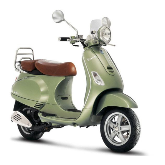
- Page 1 Service station manual 633852 IT - 633853 EN - 633854 FR - 633855 DE - 633856 ES - 633857 PT - 633858 NL - 633859 EL LXV 125...
- Page 2 Service station manual LXV 125 The descriptions and illustrations given in this publication are not binding. While the basic specifications as described and illustrated in this manual remain unchanged, PIAGGIO-GILERA reserves the right, at any time and without being required to update this publication beforehand, to make any changes to components, parts or accessories, which it considers necessary to improve the product or which are required for manufacturing or construction reasons.
- Page 3 Service station manual LXV 125 This service station manual has been drawn up by Piaggio & C. Spa to be used by the workshops of Piaggio-Gilera dealers. It is assumed that the user of this manual for maintaining and repairing Piaggio vehicles has a basic knowledge of mechanical principles and vehicle repair technique procedures.
-
Page 4: Index Of Topics
INDEX OF TOPICS CHAR HARACTERISTICS TOOL OOLING MAIN AINTENANCE TROUBL ROUBLESHOOTING ELE SYS LECTRICAL SYSTEM ENG VE NGINE FROM VEHICLE NGINE SUSP USPENSIONS BRAK SYS RAKING SYSTEM CHAS HASSIS PRE DE DELIVERY TIME... - Page 5 INDEX OF TOPICS CHAR HARACTERISTICS...
-
Page 6: Safety Rules
LXV 125 Characteristics Rules This section describes general safety rules for any maintenance operations performed on the vehicle. Safety rules - If work can only be done on the vehicle with the engine running, make sure that the premises are well- ventilated, using special extractors if necessary;... -
Page 7: Vehicle Identification
LXV 125 Characteristics Vehicle identification VEHICLE IDENTIFICATION Specification Desc./Quantity Engine prefix ZAP M444M Chassis prefix ZAP M443010000÷0000 Dimensions and mass WEIGHTS AND DIMENSIONS Specification Desc./Quantity Kerb weight 114 ± 5 kg Overall height 1180 mm Width 740 mm Wheelbase 1280 mm... -
Page 8: Electrical System
LXV 125 Characteristics Engine ENGINE Specification Desc./Quantity Engine Single-cylinder, 4-stroke Piaggio LEADER Timing system Single overhead camshaft (SOHC) with 2 valves Valve clearance intake 0.10 outlet 0.15 Bore x stroke 57.0 x 48.6 mm Cubic capacity 124 cc Carburettor KEIHIN CVK26 Engine idle speed 1650 ±... -
Page 9: Wheels And Tyres
LXV 125 Characteristics Brakes BRAKES Specification Desc./Quantity Front brake Disc brake (Ø 200 mm) with hydraulic control (lever on the far right of the handlebar) and fixed calliper. Rear brake Ø110 mm drum brake Wheels and tyres WHEELS AND TYRES Specification Desc./Quantity... -
Page 10: Crankcase And Crankshaft
LXV 125 Characteristics Specification Desc./Quantity Starter pin travel 10 mm (at 24°) Starter resistance 20 Ohm (at 24°) Tightening Torques LUBRICATION Name Torque in Nm Hub oil drainage cap 15 ÷ 17 Oil filter 4 ÷ 6 Oil pump cover screws... -
Page 11: Front Suspension
LXV 125 Characteristics Name Torque in Nm Starter motor fixing screw 11 ÷ 13 Muffler to crankcase fixing screws 24 ÷ 27 Engine oil drainage cap 24 ÷ 30 STEERING ASSEMBLY Name Torque in Nm Steering upper ring nut 35 ÷ 40... -
Page 12: Piston Rings
LXV 125 Characteristics Name Initials Cylinder Piston Play on fitting Coupling 2nd increase 57.380 ÷ 57.387 57.333 ÷ 57.340 0.040 - 0.054 Coupling 2nd increase 57.387 ÷ 57.394 57.340 ÷ 57.347 0.040 - 0.054 Coupling 2nd increase 57.394 ÷ 57.401 57.347 ÷... - Page 13 LXV 125 Characteristics Crankcase - crankshaft - connecting rod AXIAL CLEARANCE BETWEEN CRANKSHAFT AND CONNECTING ROD Name Description Dimensions Initials Quantity Half-shaft, transmission 16.6 +0-0.05 D = 0.20 - 0.50 side Flywheel-side half-shaft 16.6 +0-0.05 D = 0.20 - 0.50 Connecting rod with PP 18 -0.10 -0.15...
- Page 14 LXV 125 Characteristics Slot packing system - Provisionally fit the piston into the cylinder, without any base gasket. - Assemble a dial gauge on the specific tool - Set the dial gauge to zero at a contrast plane with an average precharge, for example 5 mm. Keeping the zero setting position, fit the tool on the cylinder and lock it with 2 nuts, as shown in the figure.
- Page 15 LXV 125 Characteristics Products RECOMMENDED PRODUCTS TABLE Product Description Specifications AGIP ROTRA 80W-90 Rear hub oil SAE 80W/90 Oil that exceeds the re- quirements of API GL3 specifications AGIP BRAKE 4 Brake fluid FMVSS DOT 4 Synthetic fluid AGIP CITY HI TEC 4T...
- Page 16 INDEX OF TOPICS TOOL OOLING...
- Page 17 LXV 125 Tooling APPROPRIATE TOOL Stores code Description 001330Y Tool for fitting steering seats 001467Y009 Driver for OD 42-mm bearings 001467Y013 Pliers to extract ø 15-mm bearings 002465Y Pliers for circlips 005095Y Engine support 008564Y Flywheel extractor TOOL - 17...
- Page 18 LXV 125 Tooling Stores code Description 020004Y Punch for removing fifth wheels from headstock 020055Y Wrench for steering tube ring nut 020074Y Support base for checking crankshaft alignment 020150Y Air heater support 020151Y Air heater 020193Y Oil pressure gauge TOOL - 18...
- Page 19 LXV 125 Tooling Stores code Description 020262Y Crankcase splitting strip 020263Y Sheath for driven pulley fitting 020287Y Clamp to assemble piston on cylinder 020306Y Punch for assembling valve seal rings 020329Y MityVac vacuum-operated pump 020330Y Stroboscopic light to check timing...
- Page 20 LXV 125 Tooling Stores code Description 020331Y Digital multimeter 020332Y Digital rev counter 020333Y Single battery charger 020334Y Multiple battery charger TOOL - 20...
- Page 21 LXV 125 Tooling Stores code Description 020335Y Magnetic support for dial gauge 020357Y 32 x 35 mm adaptor 020359Y 42x47-mm adaptor 020360Y Adaptor 52 x 55 mm 020363Y 20 mm guide 020364Y 25-mm guide TOOL - 21...
- Page 22 LXV 125 Tooling Stores code Description 020368Y driving pulley lock wrench 020375Y Adaptor 28 x 30 mm 020376Y Adaptor handle 020382Y011 adapter for valve removal tool 020409Y Multimeter adaptor - Peak voltage detec- tion TOOL - 22...
- Page 23 LXV 125 Tooling Stores code Description 020412Y 15 mm guide 020414Y 28-mm guide 020423Y driven pulley lock wrench 020424Y Driven pulley roller casing fitting punch 020425Y Punch for flywheel-side oil seal 020426Y Piston fitting fork TOOL - 23...
- Page 24 LXV 125 Tooling Stores code Description 020427Y Piston fitting band 020428Y Piston position check support 020430Y Pin lock fitting tool 020431Y Valve oil seal extractor 020434Y Oil pressure control fitting 020444Y Tool for fitting/ removing the driven pulley clutch TOOL - 24...
- Page 25 LXV 125 Tooling Stores code Description 020565Y Flywheel lock calliper spanner 020622Y Transmission-side oil guard punch TOOL - 25...
-
Page 26: Maintenance
INDEX OF TOPICS MAIN AINTENANCE... -
Page 27: Maintenance Chart
LXV 125 Maintenance Maintenance chart EVERY 2 YEARS Action Brake fluid - change EVERY 3000 KM Action Engine oil - level check/ top-up AFTER 1000 KM Action Engine oil - replacement Hub oil - change Oil filter (net filter) - clean... - Page 28 LXV 125 Maintenance Action Driving belt - replacement Odometer gear - greasing Steering - adjustment Brake control levers - greasing Brake pads - check condition and wear Brake fluid level - check Transmission elements - lubrication Safety locks - check...
- Page 29 LXV 125 Maintenance AFTER 36000 KM 300' Action Engine oil - replacement Hub oil - change Spark plug - replacement Air filter - clean Engine oil - change Oil filter (net filter) - clean Valve clearance - adjustment Idle speed (*) - adjustment...
-
Page 30: Checking The Spark Advance
LXV 125 Maintenance Checking the spark advance The ignition advance is determined electronically on the basis of parameters known by the control unit. For this reason it is not possible to interpret the reference values based on the engine rpm. - Page 31 LXV 125 Maintenance - Select the stroboscopic light command in the tra- ditional four-stroke engine position (1 spark 2 revs). - Check that the real values of rpm and ignition advance match those measured using the diag- nostic tester. If the values do not correspond, check:...
-
Page 32: Level Check
LXV 125 Maintenance - Operating on the flash bulb phase difference cal- ibrator, make the reference on the flywheel cover coincide with the fan reference as shown in the photograph. Read the advance degrees indicated by the stroboscopic light and compare them with those specified. -
Page 33: Headlight Adjustment
LXV 125 Maintenance Top-up Proceed as follows: - Remove the tank cap by loosening the two screws, remove the gasket and top up using only the liquid specified without exceeding the maxi- mum level. CAUTION ONLY USE DOT 4-CLASSIFIED BRAKE FLUID. - Page 34 LXV 125 Maintenance ground to the centre of vehicle headlamp and high- er than 7/10; 3. If it is, loosen the headlight support fixing screws and adjust the headlight direction. N.B. THE ABOVE PROCEDURE COMPLIES WITH THE EURO- PEAN STANDARDS REGARDING MAXIMUM AND MINI- MUM HEIGHT OF LIGHT BEAMS.
- Page 35 LXV 125 Maintenance - Remove the 6 flywheel cover screws indicated in the photograph and remove the flywheel cover. - Remove the filter indicated in the photograph - Check that the gasket is in good conditions - Check the SAS filter housing for dents or defor- mations - Clean the SAS filter carefully.
-
Page 36: Troubleshooting
INDEX OF TOPICS TROUBL ROUBLESHOOTING... -
Page 37: Poor Performance
LXV 125 Troubleshooting Engine Poor performance POOR PERFORMANCE Possible Cause Operation Air filter blocked or dirty. Dismantle the sponge, wash with water and shampoo, then soak it in a mixture of 50% petrol and 50% of specific oil (Se- lenia Air Filter Oil), then hand dry without squeezing, allow to drip dry and then reassemble. - Page 38 LXV 125 Troubleshooting Possible Cause Operation Failing automatic starter on the carburettor Check the electrical wiring and mechanical movement, replace if necessary. Start-up enabling buttons failure Check continuity using an Ohm meter, with the switch pressed; replace if necessary Carburettor nozzles clogged or dirty Dismantle, wash with solvent and dry with compressed air Air filter obstructed or dirty.
-
Page 39: Excessive Fuel Consumption
LXV 125 Troubleshooting High fuel consumption EXCESSIVE FUEL CONSUMPTION Possible Cause Operation Air filter blocked or dirty. Clean according to the procedure Starter inefficient Check: electric wiring, circuit continuity, mechanical sliding and power supply Loose nozzles Check the maximum and minimum nozzles are adequately... - Page 40 LXV 125 Troubleshooting Electrical system Battery BATTERY Possible Cause Operation Battery The battery is the electrical device in the system that requires the most frequent inspections and thorough maintenance. If the vehicle is not used for some time (1 month or more) the battery needs to be recharged periodically.
-
Page 41: Noisy Suspension
LXV 125 Troubleshooting Noisy suspension NOISY SUSPENSION Possible Cause Operation Noisy suspension If the front suspension is noisy, check: that the front shock ab- sorber works properly and the ball bearings are good condition. Finally, check the locking torque of the wheel axle nut, the brake calliper and the disc. -
Page 42: Electrical System
INDEX OF TOPICS ELE SYS LECTRICAL SYSTEM... - Page 43 LXV 125 Electrical system LEGENDA (Con pompa elettrica): 1. Dispositivo di accensione elettronica 2. Antenna immobilizer 3. Sensore di temperatura esterna 4. Volano magnete - Pick-up 5. Deviatore arresto motore 6. T.P.S. 7. Riscaldatore carburatore 8. Starter automatico 9. Commutatore a chiave 10.
- Page 44 LXV 125 Electrical system 20. Clacson 21. Pulsante clacson 22. Lampada illuminazione targa 23. Indicatore di direzione posteriore sinistro 24. Lampada luce di stop e di posizione posteriore 25. Indicatore di direzione posteriore destro 26. Indicatore di direzione anteriore sinistro 27.
- Page 45 LXV 125 Electrical system KEY: 1. Magneto flywheel 2. Electronic ignition device 3. Immobilizer aerial 4. Diagnostics socket 5. TPS potentiometer 6. Voltage regulator 7. Key switch 8 Engine stop switch 9. Automatic starter 10. Carburettor heater 11. Fuse-box 12. Battery 13.
- Page 46 LXV 125 Electrical system 20. Turn indicator switch 21. Left turn rear indicator lamp 22. Rear headlight assembly with tail light/stop light bulb 23. License plate bulb 24. Right turn rear indicator lamp 25. Light switch 26. Left turn front indicator lamp 27.
- Page 47 LXV 125 Electrical system Ignition LEGENDA (Con pompa elettrica): 1. Dispositivo di accensione elettronica 2. Antenna immobilizer 5. Deviatore arresto motore 9. Commutatore a chiave 11. Fusibili principali 12. Batteria 39. Bobina A.T. 40. Candela ELE SYS - 47...
- Page 48 LXV 125 Electrical system KEY: 1. Magneto flywheel 2. Electronic ignition device 3. Immobilizer aerial 6. Voltage regulator 7. Key switch 8 Engine stop switch 11. Fuse-box 12. Battery 37. Spark plug 38. High voltage coil ELE SYS - 48...
- Page 49 LXV 125 Electrical system Headlights and automatic starter section LEGENDA (Con pompa elettrica): 1. Dispositivo di accensione elettronica 5. Deviatore arresto motore 7. Riscaldatore carburatore 8. Starter automatico 9. Commutatore a chiave 11. Fusibili principali 12. Batteria 17. Fusibili secondari 22.
- Page 50 LXV 125 Electrical system D. Spia pressione olio E. Spia immobilizer 33. Relé luce anabbagliante 34. Relé luce abbagliante 35. Deviatore luci con sprazzo KEY: 2. Electronic ignition device 7. Key switch 9. Automatic starter 10. Carburettor heater 11. Fuse-box 12.
- Page 51 LXV 125 Electrical system 33. Instrument panel Battery recharge and starting LEGENDA (Con pompa elettrica): 1. Dispositivo di accensione elettronica 4. Volano magnete - Pick-up 5. Deviatore arresto motore 9. Commutatore a chiave 10. Regolatore di tensione 11. Fusibili principali 12.
- Page 52 LXV 125 Electrical system KEY: 1. Magneto flywheel 6. Voltage regulator 7. Key switch 8 Engine stop switch 11. Fuse-box 12. Battery 13. Starter motor 14. Starter remote control 15. Starter button 17. Fuse-box 18. STOP button on front brake 19.
- Page 53 LXV 125 Electrical system Level indicators and enable signals section LEGENDA (Con pompa elettrica): 1. Dispositivo di accensione elettronica 2. Antenna immobilizer 3. Sensore di temperatura esterna 5. Deviatore arresto motore 6. T.P.S. 9. Commutatore a chiave 11. Fusibili principali 12.
- Page 54 LXV 125 Electrical system KEY: 2. Electronic ignition device 3. Immobilizer aerial 4. Diagnostics socket 5. TPS potentiometer 7. Key switch 11. Fuse-box 12. Battery 17. Fuse-box 31. Fuel level warning light control 32. Low oil warning light control 33. Instrument panel 39.
-
Page 55: Devices And Accessories
LXV 125 Electrical system Devices and accessories LEGENDA (Con pompa elettrica): 1. Dispositivo di accensione elettronica 5. Deviatore arresto motore 9. Commutatore a chiave 11. Fusibili principali 12. Batteria 17. Fusibili secondari 19. Commutatore lampeggiatori 20. Clacson 21. Pulsante clacson 23. - Page 56 LXV 125 Electrical system D. Spia pressione olio E. Spia immobilizer 31. Predisposizione spia acustica indicatori di direzione 36. Pompa carburante 37. Dispositivo di gestione pompa 1. +Chiave 3. Massa pompa 4. +Pompa 5. Massa 6. Giri motore KEY: 2. Electronic ignition device 7.
-
Page 57: Checks And Inspections
LXV 125 Electrical system 24. Right turn rear indicator lamp 26. Left turn front indicator lamp 28. Right turn front indicator lamp 33. Instrument panel 34. Horn button 35. Horn 36. Turn indicators sound alarm wiring Checks and inspections This section is devoted to the checks on the electrical system components. - Page 58 LXV 125 Electrical system • presenza tensione batteria fra i terminali 8-12 e terminale 8-massa telaio del connettore grande (alimentazione fissa). Nel caso non vi fosse tensione verificare efficienza fusibile n ° 1 e relativo cablaggio. Con interruttore chiave in ON, interruttore arresto emergenza motore in RUN: •...
-
Page 59: Diagnostic Codes
LXV 125 Electrical system Characteristic MASTER key: RED KEY SERVICE key. BLACK KEY Diagnostic codes The immobiliser system is tested each time the ig- nition-key switch is turned from OFF to ON. During this diagnosis phase a number of control unit sta- tuses can be seen and various light codes dis- played. - Page 60 LXV 125 Electrical system LED remains permanently OFF. The engine can be started. 5. Programmed control unit - fault detected: a light code is displayed according to the fault detected, after which the LED remains on steadily. The engine cannot be started. The codes that can be trans- mitted are: •...
-
Page 61: Ignition Circuit
LXV 125 Electrical system Diagnostic code - 3 flashes A three-flash code indicates a system where the control unit does not recognise the key. Turn the switch to ON using several keys: if the error code is repeated even with the Master key, replace the control unit. - Page 62 LXV 125 Electrical system Pick-up resistance value Pick-up resistance value: 105 ÷ 124 Ohm - HV primary coil check Disconnect the control unit connector and check that the cable between terminal No. 4 (violet) and terminal No. 12 (black) is not interrupted (see fig- ure).
- Page 63 LXV 125 Electrical system - Pick-Up Disconnect the control unit connector and connect the positive terminal to connector No. 3 and the negative terminal to connector No. 12 (see figure). Use the start-up system to run the engine and measure the voltage produced by the Pick-Up.
-
Page 64: Stator Check
LXV 125 Electrical system 020334Y Multiple battery charger Stator check - With a tester, check the circuit between connec- tions 5-3 and 5-1 is not interrupted. - Check the earth isolation on the three phases of stators 5-earth, 3-earth, 1-earth. - Page 65 LXV 125 Electrical system In case the generated current value is lower than 10A, repeat the test using a new regulator and/stator alternatively. Choke Inspection With the connector connected to the system, check if there is voltage in both battery terminals while the engine is running.
- Page 66 LXV 125 Electrical system Turn signals system check - If the turn indicators do not work, proceed as fol- lows: - Disconnect the control unit connector and check that there is voltage between terminal No. 9 (Blue) and terminal No. 12 (Black) and the earth connec- tion with the key switch set to "ON".
- Page 67 LXV 125 Electrical system Fuses L'impianto elettrico è protetto da due fusibili da 15A «B» collocati accanto alla batteria e da due fusibili da 7,5A «A» collocati sotto la calandra an- teriore. Per rimuovere la calandra anteriore è nec- essario togliere, con l'ausilio di un cacciavite, la...
- Page 68 LXV 125 Electrical system Specification Desc./Quantity Instrument panel light bulbs Type: All glass Power: 12V 1.2W Quantity: 4 License plate light bulb Type: ALL GLASS Power: 12V - 5W Quantity: 1 Sealed battery If the vehicle is provided with a sealed battery, the only maintenance required is the check of its charge and recharging, if necessary.
- Page 69 LXV 125 Electrical system Commissioning dry-charged batteries : 1) - Remove the short closed tube and the caps, then pour sulphuric acid into the cells using the type specified for batteries with a specific gravity of 1.26, corresponding to 30 Be at a minimum tem- perature of 15°C until the upper level is reached.
- Page 70 LXV 125 Electrical system After restoring the electrolyte level, check its density using an appropriate densitometer (see the figure). When the battery is charged, you should detect a density of 30 to 32 Bé corresponding to a specific weight of 1.26 to 1.28 at a temperature of no lower than 15° C.
-
Page 71: Index Of Topics
INDEX OF TOPICS ENG VE NGINE FROM VEHICLE... - Page 72 LXV 125 Engine from vehicle Exhaust assy. Removal - Remove the 2 fixing nuts from the manifold to the head - Unscrew the 2 screws fixing the muffler to the housing; then remove the whole muffler paying at- tention to the interference between its supporting bracket and the cooling cover.
- Page 73 LXV 125 Engine from vehicle - Remove the throttle control cable from the car- burettor, indicated in the photograph - Remove the fuel supply pipe from the carburettor - Remove the fuel valve low-pressure pipe from the manifold as shown in the photograph...
- Page 74 LXV 125 Engine from vehicle - Remove the protection sheath indicated in the figure and disconnect the automatic starter, car- burettor heater and TPS connectors - Unscrew the engine pin-swinging arm nut on the right-hand side of the vehicle and slide off the pin...
- Page 75 INDEX OF TOPICS NGINE...
-
Page 76: Automatic Transmission
LXV 125 Engine This section describes the operations to be carried out on the engine and the tools to be used. Automatic transmission Transmission cover - To remove the transmission cover it is necessary to remove the rear plastic cover first by inserting a screwdriver in the corresponding slotted holes. - Page 77 LXV 125 Engine AGIP GREASE MU3 Grease for odometer transmission gear case Soap-based lithium grease with NLGI 3; ISO-L- XBCHA3, DIN K3K-20 - Operating the starter lever, load the spring and introduce the pinion in its seat. - Refit the intake throat with the 3 screws and the Kick-starter cover with the 4 screws.
-
Page 78: Removing The Driven Pulley Shaft Bearing
LXV 125 Engine Removing the driven pulley shaft bearing - Remove the clip from the inside of the cover. - Use the specific tools to remove the bearing from the crankcase. CAUTION USE AN APPROPRIATE REST SURFACE TO AVOID DAM- AGING THE COVER PAINT. -
Page 79: Removing The Driven Pulley
LXV 125 Engine 020357Y 32 x 35 mm adaptor 020412Y 15 mm guide Removing the driven pulley - Remove the spacer, the clutch bell and the whole driven pulley unit. N.B. THE UNIT CAN ALSO BE REMOVED WITH THE DRIVING PULLEY MOUNTED. -
Page 80: Removing The Clutch
LXV 125 Engine - Using a feeler pin gauge and the magnetic base, measure the bell eccentricity. - Repeat the measurement in 3 positions (Central, internal, external). - If faults are found, replace the bell. Specific tooling 020074Y Support base for checking crankshaft... - Page 81 LXV 125 Engine Inspecting the clutch - Check the thickness of the clutch mass friction material. - The masses must not show traces of lubricants; otherwise, check the driven pulley unit seals. N.B. UPON RUNNING-IN, THE MASSES MUST EXHIBIT A CEN- TRAL CONTACT SURFACE AND MUST NOT BE DIFFER- ENT FROM ONE ANOTHER.
- Page 82 LXV 125 Engine 020375Y Adaptor 28 x 30 mm 020376Y Adaptor handle 020439Y 17 mm guide Inspecting the driven fixed half-pulley - Measure the external diameter of the pulley bush- ing. Characteristic Minimum diameter permitted Ø 40.96 mm Standard diameter Ø...
-
Page 83: Refitting The Driven Pulley
LXV 125 Engine Refitting the driven half-pulley bearing - Assemble a new roller case using the specific punch, fit the bearing with the label facing outward and insert it completely up to the punch on the half- pulley. N.B. REST THE HALF-PULLEY ON A WOOD SURFACE TO AVOID DAMAGING THE THREADED RINGLET OF THE DRIVEN PULLEY UPON REMOVING IT. - Page 84 LXV 125 Engine 020263Y Sheath for driven pulley fitting Recommended products AGIP GREASE SM 2 Grease for the tone wheel revolving ring Soap-based lithium grease containing NLGI 2 Mo- lybdenum disulphide; ISO-L-XBCHB2, DIN KF2K-20 Inspecting the clutch spring - Measure the unloaded length of the spring of the movable driven half-pulley.
- Page 85 LXV 125 Engine - Support the driven pulley spring compressor ap- propriate tool with the control screw in vertical axis. - Arrange the tool with the medium length pins screwed in position "C" on the inside. - Introduce the adapter ring 11 with the chamfering facing upwards.
- Page 86 LXV 125 Engine 020444Y Tool for fitting/ removing the driven pulley clutch 020444Y011 adapter ring 020444Y009 46x55 Wrench Locking torques (N*m) Nut locking clutch unit on pulley 55 ÷ 60 Nm Refitting the driven pulley - Reassemble the clutch bell and spacer.
-
Page 87: Removing The Driving Pulley
LXV 125 Engine Removing the driving pulley - Lock the driving pulley with the specific tool as shown in the figure. - Disassemble the central nut and the Belleville washer, remove the drive and the 2 washers. - Remove the stationary half pulley and the steel washer. - Page 88 LXV 125 Engine - Check the guide shoes for the variator back-plate are not worn. - Check there is no wear in the roller housing, and the surfaces in contact with the belt on either of the pulley halves. Refitting the driving pulley...
- Page 89 LXV 125 Engine Refitting the transmission cover - Check the presence of the 2 centring dowels and the correct installation of the sealing gasket for the oil sump on the transmission cover. - Replace the cover tightening the 10 screws at the specified torque.
- Page 90 LXV 125 Engine Removing the wheel axle Remove the intermediate gear and the complete hub cover. Removing the hub bearings - Check the state of the bearings being examined (wear, clearance and noisiness). If faults are de- tected, do the following.
- Page 91 LXV 125 Engine With the appropriate tools, remove the oil seal as shown in the figure. Specific tooling 020376Y Adaptor handle 020359Y 42x47-mm adaptor Removing the driven pulley shaft bearing If it is necessary to remove the driven pulley shaft, from the relevant bearing and oil seal, remove driven pulley.
- Page 92 LXV 125 Engine Inspecting the hub cover - Check that the fitting surface is not dented or distorted. - Check the capacity of the bearings and the brake camshaft. - If faults are found, replace the hub cover. Refitting the driven pulley shaft bearing...
- Page 93 LXV 125 Engine • Assemble the Seeger ring. • Assemble the oil seal flush with the in- ternal surface as shown in the figure to the hub using the adequate tools and with the seal lip towards the inside of the hub.
- Page 94 LXV 125 Engine Refitting the ub cover - Fit a new gasket together with the centring dow- els. - Fit the gearbox cover, making sure the breather pipe is in the correct position. - Screw the 7 screws to the specified torque, po- sitioning the support plate of the pipe in the posi- tion shown in the figure.
-
Page 95: Cooling Fan
LXV 125 Engine mm. Remember that such operation must have performed on a disassembled manifold which must be cleaned afterwards. Cooling fan - Refit the parts in reverse order of the removal operation. - Make sure that there are spacers with the two rear retainers of the housing. - Page 96 LXV 125 Engine Refitting the stator - Refit the stator and flywheel carrying out the re- moval procedure in reverse, tightening the retain- ers to the specified torque. - Place the cable harness as shown in the figure. N.B. THE PICK-UP WIRE SHOULD BE POSITIONED BETWEEN THE UPPER SCREW AND THE REFERENCE PIN AS SHOWN IN THE DETAIL DRAWING.
- Page 97 LXV 125 Engine Inspecting the flywheel components - Check the integrity of the internal plastic parts of the flywheel and the Pick-Up control plate. Refitting the flywheel magneto - Fit the flywheel being careful to insert the key properly. - Lock the flywheel nut to the prescribed torque - Check that the Pick-Up air gap is between 0.34...
- Page 98 LXV 125 Engine Removing the timing system drive - Remove the parts listed below first: transmission cover, belt driving pulley, oil pump pulley cover and pinion separator washer. - Remove the tappet cover. - Remove the central screw fastener and the au- tomatic valve-lifter retaining cover, as shown in the figure.
-
Page 99: Removing The Cam Shaft
LXV 125 Engine Removing the cam shaft - Remove the two screws and the cam shaft re- tainer shown in the diagram. - Remove the cam shaft. - Remove the pin of the rocking levers from the flywheel side holes. -
Page 100: Removing The Valves
LXV 125 Engine Removing the valves - Using the specific tool fitted with the element shown in the figure, remove the cotters, the plates and the spring between the valves. Specific tooling 020382Y Valve cotters equipped with part 012 removal tool 020382Y011 adapter for valve removal tool - Remove the oil seals with the appropriate tool. -
Page 101: Inspecting The Small End
LXV 125 Engine Inspecting the small end - Measure the internal diameter of the small end using an internal micrometer. N.B. IF THE DIAMETER OF THE ROD SMALL END EXCEEDS THE MAXIMUM DIAMETER ALLOWED, SHOWS SIGNS OF WEAR OR OVERHEATING REPLACE THE CRANKSHAFT AS DESCRIBED IN THE "CRANKCASE AND CRANK-... -
Page 102: Inspecting The Piston
LXV 125 Engine - Measure the outside diameter of the piston, per- pendicular to the gudgeon pin axis. - Measure 36.5 mm from the piston crown's shown in the figure. N.B. THE PIN HOUSINGS HAVE 2 LUBRICATION CHANNELS. FOR THIS REASON MEASUREMENT OF THE DIAMETER MUST BE CARRIED OUT ACCORDING TO THE AXIS OF THE PISTON. -
Page 103: Removing The Piston
LXV 125 Engine STANDARD COUPLING CLEARANCE Name Description Dimensions Initials Quantity Top piston ring 0.025 ÷ 0.070 Middle piston ring 0.015 ÷ 0.060 oil scraper 0.015 ÷ 0.060 MAXIMUM ADMITTED CLEARANCE AFTER USE Name Description Dimensions Initials Quantity Top piston ring 0.080 mm... - Page 104 LXV 125 Engine Refitting the piston rings - Place the oil scraper spring on the piston. - Refit the oil scraper ring with the join of spring ends on the opposite side from the ring gap and the word 'TOP' towards the crown of the piston.
-
Page 105: Inspecting The Cylinder Head
LXV 125 Engine 020427Y Piston fitting band Inspecting the cylinder head - Using a trued bar check that the cylinder head surface is not worn or distorted. - Check that the camshaft and rocking lever pin bearings show no signs of wear. - Page 106 LXV 125 Engine - Remove the central screw and the tensioner spring. Check that the one-way mechanism is not worn. - Check the condition of the tensioner spring. - If examples of wear are found, replace the whole assembly. Inspecting the valve sealings - Measure the width of the sealing surface on the valve seats.
- Page 107 LXV 125 Engine - If the width of the impression on the valve seat or the diameter of the valve guide exceed the speci- fied limits, replace the cylinder head. - Check width of the impression on the valve seat «V»...
- Page 108 LXV 125 Engine 79.6 mm - If the checks above give no failures, you can use the same valves. For best sealing results, it is ad- visable to grind the valves. Grind the valves gently with a fine-grained lapping compound. During grinding, keep the cylinder head in a horizontal position.
-
Page 109: Inspecting The Cam Shaft
LXV 125 Engine Refitting the valves - Lubricate the valve guides with engine oil. - Place the lower plates of the valve spring on the head. - Use the punch to fit the 2 sealing rings one at a time. - Page 110 LXV 125 Engine - Check there is no wear on the cam shaft retaining plate and its associated groove on the cam shaft. - If any of the above dimensions are outside the specified limits, or there are signs of excessive wear, replace the defective components with new ones.
- Page 111 LXV 125 Engine -Screw the nuts and lock them in a crossed sequence and in 2 or 3 stages to the specific torque. Locking torques (N*m) Locking torque 28 ÷ 30 - Fit the two screws on the outside of the timing chain side and tighten them to the specified torque.
- Page 112 LXV 125 Engine - Refit the spacer on the cam shaft. - Rotate the engine so that the piston is at top dead centre, using the reference marks on the flywheel and the crankcase. - While doing so, fit the chain onto the control cam- shaft pulley and keep the reference 2V in corre- spondence with the reference mark on the head.
- Page 113 LXV 125 Engine Locking torques (N*m) Locking torque 11 ÷ 13 - Insert the chain tensioning screw, together with the spring and washer, tightening it to the prescribed torque. Locking torques (N*m) Locking torque 5 - 6 - Adjust the valve clearance.
-
Page 114: Crankcase - Crankshaft
LXV 125 Engine - Refit the cylinder head cover, tightening the 4 clamping screws to the prescribed torque. - Refit the fan and the housing. - Reassemble the oil pump control, the chain com- partment cover, the by-pass and the oil sump as described in the lubrication chapter. - Page 115 LXV 125 Engine 0.15 ÷ 0.40 mm Splitting the crankcase halves Remove the 11 coupling screws to the crankcase. - Separate the crankcase while keeping the crank- shaft in one of the two halves of the crankcase. Remove the crankshaft.
- Page 116 LXV 125 Engine - Check the radial clearance on the connecting rod. -Check the surfaces that limit the axial free-play are not scored and measure the width of the crank- shaft between these surfaces, as shown in the diagram. CAUTION BE CAREFUL NOT TO LET THE MEASUREMENT BE AF- FECTED BY THE UNIONS WITH THE CRANKSHAFT ENDS.
- Page 117 LXV 125 Engine Inspecting the crankshaft alignment To install the drive shaft on the support and to measure the misalignment in the 4 points indicated in figure. - Check that the driving shaft cone, the tab seat, the oil seal capacity, the toothed gear and the threaded tangs are in good working order.
- Page 118 LXV 125 Engine Inspecting the crankcase halves - Before proceeding to check the crankcase halves, thoroughly clean the all surfaces and oil ducts. - On the transmission side crankcase half, take particular care cleaning the housing and oil ducts for the following components: the oil pump, the oil by-pass valve, the main bushings and the cooling jet on the transmission side (see diagram).
- Page 119 LXV 125 Engine - Check the main bearing seats that limit axial clearance in the crankshaft show no signs of wear. The dimension between these seats is measured by way of the procedure described previously for measuring the crankshaft axial clearance and di- mensions.
-
Page 120: Main Bearings
LXV 125 Engine - The bushing housings in the crankcase are classified into 2 categories - Cat. 1 and Cat. 2 - just like those for the crankshaft. 3 - The main bushings are subdivided into 3 thickness categories; see the table below: N.B. - Page 121 LXV 125 Engine - Lubricate the main bushings and insert the crank- shaft in the transmission side crankcase half. - Reassemble the two crankcase halves. - Fit the 11 screws and tighten them to the pre- scribed torque. N.B. WHEN FITTING THE HALF CASING AND THE CRANK- SHAFT, TAKE CARE NO TO DAMAGE THE SHAFT THREA- DED TANGS.
- Page 122 LXV 125 Engine Conceptual diagrams ENG - 122...
-
Page 123: Oil Pressure Check
LXV 125 Engine Oil pressure check - After removing the cover protections as descri- bed in the "Flywheel" chapter, disconnect the elec- trical connexion of the minimum oil pressure switch and then remove the switch. - With the engine idling at 1650 rpm and the oil temperature at ~90°C, check that the oil pressure... - Page 124 LXV 125 Engine Removal - First remove the transmission cover and the com- plete driving pulley - Install the base of the appropriate tool on the oil guard using the screws provided. - Screw the threaded bar onto the base of the tool and extract the oil guard.
- Page 125 LXV 125 Engine - Preassemble the oil seal with the appropriate tool, positioning the screws - Place the sheath over the crankshaft - Insert the tool with the oil seal on the crankshaft until it comes into contact with the crankcase...
-
Page 126: Oil Pump
LXV 125 Engine - Use the nut to move the base of the tool until you can see end of the oil seal driving stroke - Remove all of the tool components following the procedure in reverse order CAUTION FAILURE TO COMPLY WITH THIS ASSEMBLY PROCEDURE CAN SERIOUSLY DAMAGE THE ENGINE DUE TO THE WRONG TENSIONING OF THE OIL PUMP CONTROL CHAIN. - Page 127 LXV 125 Engine - Remove the central screw with Belleville washer, as shown in the diagram. - Remove the chain with the pulley. - Remove the crankshaft control pinion. - Remove the oil pump acting on the 2 retainers as shown in the figure.
- Page 128 LXV 125 Engine Measure the distance between the outer rotor and the pump body; see figure. Characteristic Admissible limit clearance: 0.20 mm Check the axial clearance of the rotors with a trued bar as reference, as shown in the figure.
- Page 129 LXV 125 Engine Removing the oil sump - Remove the oil filler plug, the transmission cover, the complete drive pulley assembly with belt and the sprocket wheel, as described in the Transmis- sion chapter. - Drain the oil from the sump as described above.
- Page 130 LXV 125 Engine Refitting the oil sump - Refit the by-pass valve plunger in its housing. - Insert the pressure-regulating spring. - Fit a new sump seal. - Refit the sump, taking care to locate the spring in the appropriate recess machined into the inside of the sump.
- Page 131 LXV 125 Engine - Operate the pump slowly and check if there is an increase of pressure. A small leakage is consid- ered to be normal. If anomalies are detected, replace the pump. N.B. A MALFUNCTIONING ONE-WAY VALVE CAN RESULT IN RUBBER COUPLING AND FILTER OVERHEATING N.B.
-
Page 132: Fuel Supply
LXV 125 Engine Lack of tightness or the fact that the valve opens at different vacuum values should be regarded as anomalies. In this case, replace it. N.B. LACK OF TIGHTNESS IN THE CUT-OFF VALVE RESULTS IN EXHAUST NOISE (EXPLOSIONS IN THE MUFFLER). IN-... -
Page 133: Removing The Carburettor
LXV 125 Engine LET ON THE MANIFOLD HAS A SECTION INTENTIONALLY REDUCED FOR THE PURPOSE OF ENHANCING THE SUC- TION PULSATION AND THEREBY GUARANTEE A CON- STANT TAP FLOW RATE. Specific tooling 020329Y MityVac vacuum-operated pump Characteristic Minimum flow rate 20 cc - Completely empty the gas tank. - Page 134 LXV 125 Engine - Remove the protection, the bracket and the start- er acting on the screw shown in the figure. - Remove the 2 screws and the starter support with the gasket. - Remove the 4 fixing screws shown in the figure and the vacuum chamber cover.
- Page 135 LXV 125 Engine - Remove the vacuum valve together with the di- aphragm. - Unscrew the bayonet joint 1/8 of a turn and re- move, take out the spring and vacuum valve nee- - Remove the 4 screws indicated in the figure.
- Page 136 LXV 125 Engine - Remove the oil pump seal. - Remove the intake and outlet valves of the intake pump from the tank N.B. CAUTION, THE ACCELERATION PUMP VALVES ARE MADE UP OF NOZZLES, SPRING AND BALL. N.B. AVOID REMOVING THE PISTON OF THE PUMP AND ITS CONTROL.
- Page 137 LXV 125 Engine -Remove diffuser. - Remove the sprayer. N.B. WHEN CLEANING THE CARBURETTOR BODY REMOVE THE SPRAYER TO AVOID LOSING PARTS. IF THE SPRAY- ER IS FORCED IN ITS HOUSING DO NOT ATTEMPT TO REMOVE IT AS THIS WILL ONLY DAMAGE IT.
- Page 138 LXV 125 Engine -Remove the minimum nozzle. - Remove the minimum flow set screw and the spring. CAUTION DO NOT ATTEMPT REMOVING PARTS EMBEDDED IN THE CARBURETTOR BODY SUCH AS: FUEL SUPPLY PIPE, PLUNGER HOUSING, STARTER NOZZLE, PIT COVER FOR...
- Page 139 LXV 125 Engine - For maximum circuit, check the air adjustment is correct as shown in the figure. - For the minimum circuit, make sure the following points are properly cleaned: air gauging, outlet section controlled by flow screw, progression holes near the throttle valve.
- Page 140 LXV 125 Engine - Wash and blow the minimum nozzle properly and reassemble it. - Properly wash and blow the components of the sprayer maximum circuit, the diffuser and the noz- zle. - Introduce the sprayer in the carburettor body with the shortest cylindrical part directed to the diffuser.
- Page 141 LXV 125 Engine - Remove the drainage screw from the tank, wash and blow it properly and make sure the accelera- tion pump pipes are clean. - Operate the acceleration pump piston repeatedly and blow with compressed air. - Reassemble the acceleration pump valves fol-...
- Page 142 LXV 125 Engine Level check - Place the carburettor inclined as shown in the figure. - Check that the float reference is parallel to the tank coupling surface - If different positions are detected, change the plunger control metal plate direction to obtain the position described above.
- Page 143 LXV 125 Engine - Reassemble the spring with the pin lock. - Remove the cover of the vacuum chamber being careful to correctly insert the spring in its place on the cover. - Tighten the screws. - Wash and blow dry the starter support.
- Page 144 LXV 125 Engine With a 12V battery power the automatic starter and check that the piston protrudes as much as possi- ble. - The correct warm up time depends on the ambi- ent temperature. - If protrusion, resistance or timing values are dif-...
-
Page 145: Adjusting The Idle
LXV 125 Engine Adjusting the idle - The engine does not require frequent idle speed adjustments, but it is essential to strictly follow cer- tain rules when adjusting the idle speed. - Before adjusting the carburettor make sure to re-... -
Page 146: Index Of Topics
INDEX OF TOPICS SUSP USPENSIONS... -
Page 147: Removing The Front Wheel
LXV 125 Suspensions Front suspension This section is devoted to operations that can be carried out on the suspension. Front Removing the front wheel - Remove the five Allen screws that fix the wheel to the hub. N.B. BEFORE REMOVING THE WHEEL HUB, REMOVE THE BRAKE CALLIPER. - Page 148 LXV 125 Suspensions - Remove the oil seal on the roller bearing side using a screwdriver. - Remove the roller bearing using the specific tool Specific tooling 020376Y Adaptor handle 020456Y Ø 24 mm adaptor 020363Y 20 mm guide - Heat the roller bearing seat with a heat gun...
-
Page 149: Refitting The Front Wheel
LXV 125 Suspensions Soap-based lithium grease with NLGI 3; ISO-L- XBCHA3, DIN K3K-20 Refitting the front wheel - When refitting, tighten the 5 screws to the speci- fied torque Locking torques (N*m) Nut tightening torque 20 to 25 N•m Handlebar... -
Page 150: Steering Column
LXV 125 Suspensions Steering column Removal After removing the upper seat, lean the vehicle on one side and extract the steering tube completely from the fork. Specific tooling 020055Y Wrench for steering tube ring nut Overhaul - Press and remove the wedging washer with the help of a pointed end. - Page 151 LXV 125 Suspensions - Repeat the operation described above using the tool fitted with part 16 and part 22* instead of part 4 on the stem, on the side opposite the one shown in the figure to refit the second wedging washer - roller casing - sealing ring unit.
- Page 152 LXV 125 Suspensions - Fit both dust guard rings «C» on the swinging hub as shown in the detail drawing «A». - Connect the swinging hub to the steering tube with the guide pin, part 5*. - Use the specific tool fitted with part 3* on its stem and with part 4 at the bottom of the tool.
- Page 153 LXV 125 Suspensions - Use the specific tool, fitted with part 1*, and op- erate the handgrip until the pin and the Nadella are simultaneously ejected in the direction opposite the tool thrusting force. - To eject the second Nadella, use the tool fitted with part 2* instead of part 1, on the side opposite the one shown in the figure.
-
Page 154: Front Shock Absorber
LXV 125 Suspensions When fitting the fork, lubricate with the steering bearing tracks with the recommended grease. Tighten the lower ring nut "A" and the upper ring nut "B" to the specified torque Recommended products AGIP GREASE PV2 Grease for the steering... - Page 155 LXV 125 Suspensions Removal - Remove the steering tube - Remove the shock absorber lower clamps - Remove the shock absorber upper clamps Refitting To refit, carry out the removal operations in reverse order, observing the prescribed tightening torques. Locking torques (N*m) shock absorber lower clamp 20 - 27 shock absorber upper clamp 20 ÷...
- Page 156 LXV 125 Suspensions - Before refitting the bracket in the wheel axle, place the O-ring as shown in the photograph so that it is correctly placed after fitting the bracket. - Refit the washer and the Seeger ring. - Refit the lower screws fixing the shock absorber...
- Page 157 LXV 125 Suspensions - Suitably hold the brake calliper - shock absorber attachment bracket - Fit a new oil seal and move it until it stops using the specific tool Specific tooling 020376Y Adaptor handle 020360Y Adaptor 52 x 55 mm...
-
Page 158: Steering Bearing
LXV 125 Suspensions White anhydrous-calcium based grease to protect roller bearings; temperature range between -20 ° C and +120 °C; NLGI 2; ISO-L-XBCIB2 Steering bearing Removal - Use the specific tool both to remove the lower seat of the upper bearing and to remove the upper seat of the lower bearing fitted on the chassis. -
Page 159: Refitting The Rear Wheel
LXV 125 Suspensions Refitting the rear wheel - Fit the wheel, tighten the nut to the prescribed torque. - Refit the cap and the split pin folding it correctly as shown in the figure. Locking torques (N*m) Locking torque 137 ÷ 152 Nm... -
Page 160: Shock Absorbers
LXV 125 Suspensions Refitting For rifting, respect the locking torques Locking torques (N*m) Part C Part B Part A 33 ÷ 41 44 ÷ 52 33 ÷ 41 Shock absorbers SUSP - 160... -
Page 161: Centre-Stand
LXV 125 Suspensions Removal - To replace the shock absorber remove the bat- tery access flap to reach and remove the shock absorber/ frame anchoring nut. Then remove the shock absorber/engine anchorage nut. - When refitting, tighten the shock absorber/chas- sis anchoring nut and the shock absorber/engine pin to the prescribed torque. - Page 162 INDEX OF TOPICS BRAK SYS RAKING SYSTEM...
-
Page 163: Front Brake Calliper
LXV 125 Braking system Front brake calliper Removal - Remove the front wheel. - Remove the pad retention pin. - Using a pin partially remove the brake pad re- tention pin. - Remove the screws fixing the brake calliper to the crankcase then remove the brake calliper com- plete with pipe. - Page 164 LXV 125 Braking system - Check there are no scorings on the pistons and their seats; otherwise, replace them. - Wash and blow all the components carefully - Fit the O-rings and new dust guards - Refit the pistons in their seats being careful to...
-
Page 165: Front Brake Disc
LXV 125 Braking system - Keep the brake pads in contact with the pistons and insert the calliper in the brake disc. - Fix the calliper to the fork with the two screws with elastic washer at the prescribed torque... - Page 166 LXV 125 Braking system Removal - Remove the front wheel - Remove the front brake calliper - Remove the hub and the disc operating on the wheel axle nut - Adequately support the hub with the disc and op- erating on the five screws shown in the photo-...
-
Page 167: Disc Inspection
LXV 125 Braking system Disc Inspection - Remove the front wheel - Use a micrometer to check the disc thickness as shown in the photograph - Repeat the measurement in at least 6 points on the disk - Remove the front brake calliper... - Page 168 LXV 125 Braking system 0.5 mm thickness difference in the residual friction material is permitted Refitting - Insert the brake pads - Insert the fixing pin being careful to position the clip with the ends towards the bleed screw as in the photo.
-
Page 169: Brake Fluid Level Check
LXV 125 Braking system Front - Remove the rubber cap from the bleed screw. - Insert a rubber pipe in the bleed screw to permit the brake fluid to be recovered. - With the right-hand brake lever, load the system and bring it up to the required pressure. - Page 170 LXV 125 Braking system Front brake pump Removal - Remove the two screws fixing the brake pump to the handlebar indicated in the photograph - Remove the oil pipes joint from the pump collect- ing the brake oil in a container...
-
Page 171: Rear Drum Brake
LXV 125 Braking system 8. Spring. 9. Reservoir Refitting For refitting purposes carry out the removal operations but in reverse order respecting the tightening torque and purge the circuit. Locking torques (N*m) Oil pipe joint to the pump: 20 - 25 Brake pump fixing screws to the handle bar: 7 ÷ 10 Nm... - Page 172 LXV 125 Braking system BRAK SYS - 172...
- Page 173 INDEX OF TOPICS CHAS HASSIS...
- Page 174 LXV 125 Chassis Seat Remove the saddle opening cable Remove the four screws shown in the figure and the rear seat from the chassis saddle. Unscrew the two screws of saddle fixing hook cov- To remove the cable and the sheath: - Remove the elastic ring and unscrew the cable end from the seat on the saddle fixing hook.
-
Page 175: Instrument Panel
LXV 125 Chassis Instrument panel - Remove the front grille - Remove the shield back plate - Remove the two fixing screws of the instrument panel. - Remove the odometer cable. - Remove the connector of the electric connections from the instrument panel... - Page 176 LXV 125 Chassis Headlight assy. - Remove the four fixing screws from the light sup- port. Knee-guard - Remove the front grille. - Unscrew the 2 screws shown in the figure placed under the front grille. - Remove the 3 screws shown in the figure, placed inside the glove-box;...
-
Page 177: Air Filter
LXV 125 Chassis Footrest - Operate on the 3 screws shown in the figure once the glove-box and fairing have been removed. Air filter - Remove the helmet compartment. - after removing the side fairing, remove the 2 screws fixing the filter box to the engine, indicated in the figure. -
Page 178: Front Mudguard
LXV 125 Chassis Front mudguard - Release the front brake pipes from the calliper and the cable from the odometer - Remove the steering tube - Remove the three mudguards-steering tube clamps indicated in the figure Front central cover - Remove the "PIAGGIO" clip-on badge... - Page 179 INDEX OF TOPICS PRE DE DELIVERY...
- Page 180 LXV 125 Pre-delivery Aesthetic inspection Appearance check: - Paintwork - Fitting of plastics - Scratches - Dirt Tightening torques inspection Lock check - Safety locks - clamping screws Safety locks Rear shock absorber upper fixing Rear shock absorber lower fixing...
- Page 181 LXV 125 Pre-delivery CAUTION TO ENSURE MAXIMUM PERFORMANCE, THE BATTERY MUST BE CHARGED BEFORE USE. INADEQUATE CHARGING OF THE BATTERY WITH A LOW LEVEL OF ELECTROLYTE BEFORE IT IS FIRST USED SHORTENS BATTERY LIFE. WARNING BEFORE RECHARGING THE BATTERY, REMOVE THE CAPS OF EACH CELL.
-
Page 182: Static Test
LXV 125 Pre-delivery Static test Static control after the test ride: - Starting when warm - Starter operation - Minimum hold (turning the handlebar) - Uniform turning of the steering - Possible leaks CAUTION CHECK AND ADJUST TYRE PRESSURE WITH TYRES AT AMBIENT TEMPERATURE. - Page 183 INDEX OF TOPICS TIME...
- Page 184 LXV 125 Time Engine ENGINE Code Action Duration 001001 engine from frame - removal and re- fitting TIME - 184...
- Page 185 LXV 125 Time Crankcase CRANKCASE Code Action Duration 001133 Engine crankcase - Replacement 001153 Half crankcase gasket - Replace- ment 002031 Rear wheel hub bearings - Replace- ment TIME - 185...
- Page 186 LXV 125 Time Crankshaft CRANKSHAFT Code Action Duration 001117 Crankshaft - Replacement 001099 Oil seal, flywheel side - Replacement TIME - 186...
-
Page 187: Cylinder Assy
LXV 125 Time Cylinder assy. CYLINDER GROUP Code Action Duration 001002 Cylinder-Piston - Replacement 001107 Cylinder / piston - Inspection / clean- TIME - 187... -
Page 188: Cylinder Head Assy
LXV 125 Time Cylinder head assy. HEAD UNIT Code Action Duration 001045 Valves - Replacement 001056 Head gasket - change 001126 Head - Replacement TIME - 188... - Page 189 LXV 125 Time Rocker arms support assy. ROCKING LEVER SUPPORT UNIT Code Action Duration 001044 Camshaft - Replacement 001148 Rocking lever valve - Replacement 001049 Valves - Adjustments TIME - 189...
-
Page 190: Cylinder Head Cover
LXV 125 Time Cylinder head cover HEAD COVER Code Action Duration 001089 Head cover - Replacement 001088 Head cover gasket - Replacement 001159 Oil vapour recovery tank - Service 001093 Spark plug - Replacement 001097 Cooling hood - Replacement 001091... -
Page 191: Chain Tensioner
LXV 125 Time Chain tensioner CHAIN TIGHTENER Code Action Duration 001129 Chain tensioner - Service and Re- placement 001124 By pass lubrication - Replacement TIME - 191... -
Page 192: Oil Filter
LXV 125 Time Oil filter OIL FILTER Code Action Duration 001123 Oil filter - Replacement 001160 Oil pressure sensor - Replacement 003064 Engine oil - Change 001102 Net oil filter - Replacement / Cleaning TIME - 192... -
Page 193: Flywheel Cover
LXV 125 Time Flywheel cover FLYWHEEL COVER Code Action Duration 001087 Flywheel cover - Replacement 001163 Muffler secondary air connection - Replacement 001161 Secondary air filter - Replacement / Cleaning 001174 SAS valve - Replacement 001164 Crankcase secondary air connection... -
Page 194: Driven Pulley
LXV 125 Time Driven pulley DRIVEN PULLEY Code Action Duration 001155 Clutch bell housing - Replacement 001022 Clutch - Replacement 001012 Driven pulley - Overhaul 001110 Driven pulley - Replacement TIME - 194... -
Page 195: Oil Pump
LXV 125 Time Oil pump OIL PUMP Code Action Duration 001051 Belt/Timing chain - Change 001125 Chain guide pads - Replacement 001042 Oil pump - Service 001112 Oil pump - change 001130 Oil sump - Replacement 001100 Oil seal, clutch side - Replacement... - Page 196 LXV 125 Time Final gear assy. FINAL REDUCTION GEAR ASSEMBLY Code Action Duration 004125 Rear wheel axle - Replacement 001156 Gear reduction unit cover - Replace- ment 003065 Gear box oil - Replacement 001010 Gear reduction unit - Inspection TIME - 196...
-
Page 197: Driving Pulley
LXV 125 Time Driving pulley DRIVING PULLEY Code Action Duration 001066 Drive pulley - Removal and refitting 001086 Driving half-pulley - Replacement 001177 Variator rollers / shoes - Replace- ment 001011 Driving belt - Replacement TIME - 197... -
Page 198: Transmission Cover
LXV 125 Time Transmission cover TRANSMISSION COVER Code Action Duration 001096 Transmission crankcase cover - Re- placement 001135 Transmission cover bearing - Re- placement 001065 Transmission cover - Removal and Refit TIME - 198... -
Page 199: Starter Motor
LXV 125 Time Starter motor ELECTRICAL START-UP Code Action Duration 001020 Starter motor - Replacement 005045 Starter motor cable harness - Re- placement 001017 Starter sprocket wheel - Replace- ment 001021 Kick starter - Inspection 008008 Starter spring pack - Replacement... -
Page 200: Magneto Flywheel
LXV 125 Time Flywheel magneto MAGNETO FLYWHEEL Code Action Duration 001109 Cooling fan - Replacement 001173 Rotor - Replacement 001067 Stator - Removal and Refitting 001058 Flywheel - Replacement TIME - 200... - Page 201 LXV 125 Time Belt cooling duct BELT COOLING PIPE Code Action Duration 001170 Air manifold - replacement 001132 Transmission air inlet pipe - Replace- ment 001131 Transmission air intake - Replace- ment TIME - 201...
- Page 202 LXV 125 Time Carburettor CARBURETTOR Code Action Duration 001082 Carburettor heating resistor - Re- placement 001013 Intake manifold - change 004122 Air cleaner carburettor fitting - Re- placement 001081 Automatic choke - Replacement 001008 Carburettor - Inspection 001063 Carburettor - Replacement...
-
Page 203: Exhaust Pipe
LXV 125 Time Exhaust pipe MUFFLER Code Action Duration 001009 Muffler - Replacement 001095 Muffler guard - Replacement TIME - 203... -
Page 204: Air Cleaner
LXV 125 Time Air cleaner AIR CLEANER Code Action Duration 004122 Air cleaner carburettor fitting - Re- placement 001014 Air filter - Replacement / cleaning 001015 Air filter box - Replacement 001027 Body / air cleaner union - Replace- ment... - Page 205 LXV 125 Time Frame RAME Code Action Duration 004001 Chassis - Replacement 004023 Shield rim - Replacement 004149 Shield central cover - Replacement 004159 Plates / Stickers - Replacement 004012 Rear side panels - Replacement 004059 Spark plug inspection flap - Replace-...
- Page 206 LXV 125 Time Centre-stand STAND Code Action Duration 001053 Stand bolt - Replacement 004004 Stand - Replacement TIME - 206...
- Page 207 LXV 125 Time Footrests OOTREST Code Action Duration 004078 Front/rear footrest rubber - Replace- ment 004178 Footrest - Replacement TIME - 207...
-
Page 208: Rear Cover
LXV 125 Time Rear cover HIELD BACK PLATE Code Action Duration 004174 Trunk levers - Replacement 004065 Front shield, rear part - Removal and refitting 004081 Glove box door - Replacement 004082 Trunk gasket - Replacement TIME - 208... -
Page 209: Underseat Compartment
LXV 125 Time Underseat compartment HELMET COMPARTMENT Code Action Duration 004016 Helmet compartment - Replacement 005046 Battery cover - change 004011 Central chassis cover - Replacement 004071 Battery compartment - replacement TIME - 209... - Page 210 LXV 125 Time Plate holder LICENSE PLATE HOLDER Code Action Duration 004136 License plate support - Replacement 005048 Licence plate holder - Replacement 005032 Licence plate light glass - Replace- ment TIME - 210...
- Page 211 LXV 125 Time Mudguard MUDGUARDS Code Action Duration 004002 Front mudguard - Replacement 004009 Rear mudguard - Replacement TIME - 211...
-
Page 212: Fuel Tank
LXV 125 Time Fuel tank FUEL TANK Code Action Duration 004168 Fuel tank cap - Replacement 005010 Tank float - Replacement 004112 Cock-carburettor hose - Replace- ment 004005 Fuel tank - Replacement 004007 Fuel valve - Replacement 004109 Fuel tank breather - Replacement... -
Page 213: Rear Shock Absorber
LXV 125 Time Rear shock-absorber REAR SHOCK ABSORBER Code Action Duration 003007 Rear shock absorber - Removal and Refitting TIME - 213... - Page 214 LXV 125 Time Steering column bearings TEERING FIFTH WHEELS Code Action Duration 003002 Steering fifth wheel - Replacement 003073 Steering clearance - Adjustment 004119 Bearing / upper steering fifth wheel - Replacement TIME - 214...
-
Page 215: Handlebar Covers
LXV 125 Time Handlebar covers ODOMETER - HANDLEBAR COVERS Code Action Duration 004053 Spoiler - Replacement 004018 Handlebar front section - Replace- ment 005014 Odometer - Replacement 005038 Instrument panel warning light bulbs - Replacement 004019 Handlebar rear section - Replace-... -
Page 216: Handlebar Components
LXV 125 Time Handlebar components HANDLEBAR COMPONENTS Code Action Duration 004066 Driving mirror - Replacement 002037 Brake or clutch lever - Replacement 002071 Left hand grip - Replacement 003001 Handlebar - Removal and refitting 005017 Stop switch - Replacement 002024... -
Page 217: Swinging Arm
LXV 125 Time Swing-arm SWINGING ARM Code Action Duration 001072 Swinging arm - Engine-chassis con- nection - Replacement TIME - 217... - Page 218 LXV 125 Time Seat SADDLE Code Action Duration 004003 Saddle - Replacement 004008 Luggage rack - Replacement TIME - 218...
-
Page 219: Turn Signal Lights
LXV 125 Time Turn signal lights TURN INDICATOR LIGHTS Code Action Duration 005002 Front headlamp - Replacement 005012 Front turn indicator - Replacement 005067 Front turn indicator bulb - Replace- ment 005008 Front headlamp bulbs - Replacement 005005 Taillight - Replacement... -
Page 220: Front Wheel
LXV 125 Time Front wheel FRONT WHEEL Code Action Duration 004123 Front wheel - Replacement 003047 Front tyre - replace 003037 Front wheel rim- Replacement 003033 Front wheel hub- Replacement 002041 Front brake disc - Replacement 003034 Front wheel hub bearing - Replace-... -
Page 221: Electric Devices
LXV 125 Time REAR WHEEL Code Action Duration 004126 Rear wheel tyre - Replacement 001071 Rear wheel rim - Removal and Refit- ting 001016 Rear wheel - Replacement 002002 Rear brake pads/shoes - Replace- ment Electric devices ELECTRICAL COMPONENTS Code... -
Page 222: Electronic Controls
LXV 125 Time Electronic controls ELECTRICAL CONTROLS Code Action Duration 005039 Headlight switch - Replacement 005006 Light switch or turn indicators - Re- placement 005040 Horn button - Replacement 005003 Horn - Replacement 005041 Starter button - Replacement 005077 Emergency stop switch - Replace-... - Page 223 LXV 125 Time Transmissions TRANSMISSIONS Code Action Duration 002053 Rear brake transmission complete - Replacement 002051 Odometer transmission assembly - Replacement 002049 Odometer cable - Replacement TIME - 223...
-
Page 224: Front Suspension
LXV 125 Time Front suspension FRONT SUSPENSION Code Action Duration 003045 Steering tube - Replacement 003010 Front suspension - Service 003035 Shock absorber support and brake calliper - Replacement 001064 Odometer reel - Replacement 003044 Shock absorber cover - Replace-... -
Page 225: Braking System
LXV 125 Time Braking system BRAKING SYSTEM Code Action Duration 002021 Front brake hose - Remov. and Re- fitt. 002007 Front brake shoes/pads - Remov. and Refitt 002039 Front brake calliper - Removal and Refitting 002047 Front brake fluid and air bleeding... - Page 226 Air filter: 177 Battery: 40, 51, 63, 68 Brake: 163, 165, 167, 169–171 Brake fluid: 169 Carburettor: 9, 133, 138, 202 Fuel: 39, 132, 212 Fuses: 67 Headlight: 33, 176 Identification: 7 Instrument panel: 175 Maintenance: 6, 27 Odometer: Oil filter: 192 Saddle: Shock absorbers: 160 Spark plug: 61...
Need help?
Do you have a question about the LXV 125 and is the answer not in the manual?
Questions and answers