Peak PCAN-USB User Manual
All-in-one usb adapter for communication via can, rs-232, and usb
Hide thumbs
Also See for PCAN-USB:
- User manual (37 pages) ,
- Firmware update manual (11 pages) ,
- User manual (35 pages)

Subscribe to Our Youtube Channel
Related Manuals for Peak PCAN-USB


Summary of Contents for Peak PCAN-USB
- Page 1 PCAN-USB Hub All-in-one USB adapter for communication via CAN, RS-232, and USB User Manual Document version 2.6.0 (2019-05-28)
- Page 2 Part number PCAN-USB Hub IPEH-002004 PCAN® is a registered trademark of PEAK-System Technik GmbH. CANopen® and CiA® are registered community trade marks of CAN in Automation e.V. All other product names mentioned in this document may be the trademarks or registered trademarks of their respective companies.
-
Page 3: Table Of Contents
PCAN-USB Hub – User Manual Contents Introduction Properties at a Glance System Requirements Scope of Supply Installing the Software and the Adapter Connectors on the Adapter Upstream Port (USB Cable) Power (Voltage Supply) Connection over D-Sub connector 3.3.1 Voltage Supply of External Devices... - Page 4 PCAN-USB Hub – User Manual 5.2.1 Features of PCAN-Basic 5.2.2 Principle Description of the API 5.2.3 Notes about the License Technical Specifications Appendix A CE Certificate Appendix B Dimension Drawing Appendix C Quick Reference...
-
Page 5: Introduction
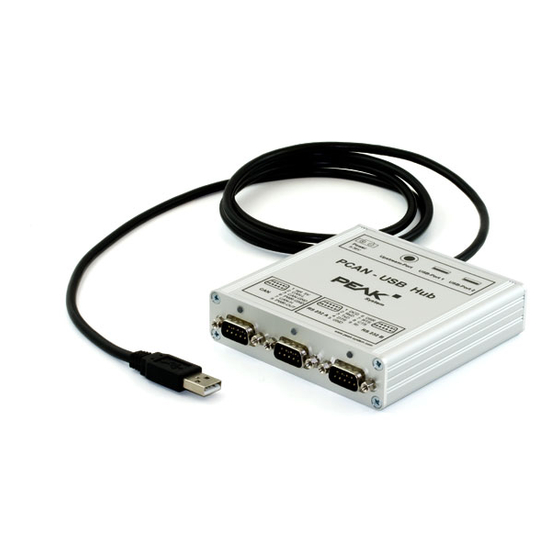
PCAN-USB Hub – User Manual Introduction The PCAN-USB Hub provides multiple hardware interfaces through a USB connection. It offers the user one CAN, two RS-232, and two further USB interfaces. Its robust aluminum casing makes the PCAN-USB Hub suitable for mobile applications. -
Page 6: System Requirements
Extended operating temperature range from -40 to 85 °C (-40 to 185 °F) Note: This manual describes the use of the PCAN-USB Hub with Windows. You can find CAN drivers for Linux and the corresponding application information on the provided DVD in the directory branch Develop and on our website under www.peak-system.com/linux. -
Page 7: Scope Of Supply
PCAN-USB Hub – User Manual Scope of Supply PCAN-USB Hub in aluminum casing Mating connector for voltage supply Device drivers for Windows 10, 8.1, 7 and Linux (32/64-bit) Device driver for Windows CE 6.x (x86 and ARMv4 processor support) CAN monitor PCAN-View for Windows... -
Page 8: Installing The Software And The Adapter
PCAN-USB Hub – User Manual Installing the Software and the Adapter This chapter covers the software setup for the PCAN-USB Hub under Windows and the connection of the hub to the computer. Drivers for the CAN interface as well as the RS-232 interfaces are installed. - Page 9 PCAN-USB Hub – User Manual Note: If you have no internet connection, install the serial driver for the device via the product DVD: Drivers/PCAN-USB Hub Serial Drivers/Windows/CMD v2.xx.xx WHQL Certified.exe. Check the LED on the adapter. If the LEDs are red, then the driver was initialized successfully.
-
Page 10: Connectors On The Adapter
PCAN-USB Hub – User Manual Connectors on the Adapter Upstream Port (USB Cable) The cable with the USB plug is used for connecting the PCAN-USB Hub to a computer. When a High-speed USB connection (USB 2.0) is established, the LED at the upstream port is on. For a Full-speed USB connection (USB 1.1) the LED stays off. -
Page 11: Connection Over D-Sub Connector
PCAN-USB Hub – User Manual Figure 1: Power socket at the rear of the PCAN-USB Hub for the external voltage supply (self-powered operation) The connection of an external power supply at the power socket is done with the supplied mating connector for fastening cable strands. -
Page 12: Voltage Supply Of External Devices
External devices with low power consumption (e.g. bus converters) can be directly supplied via the CAN connector. With a solder bridge for the one CAN channel on the PCAN-USB Hub board (casing opened), a 5-Volt supply can optionally be routed to pin 1 and the external voltage supply, if available, can be routed to pin 9 of the D-Sub CAN connector. - Page 13 Put the bottom cover on the aluminum casing and screw the four lower corner screws. Figure 3: Positions of the solder fields JP103 and JP104 on the PCB of the PCAN-USB Hub 5-Volt supply External voltage supply (9 - 36 V)
-
Page 14: Rs-232
USB Ports (Downstream) Further USB devices can be connected to the USB ports 1 and 2. Figure 5: USB ports at the back of the PCAN-USB Hub When using the USB ports, we recommend the voltage supply of the PCAN-USB Hub via the power socket (self-powered operation). -
Page 15: Cabling
The termination prevents interfering signal reflections and ensures the proper operation of the transceivers of the connected CAN nodes (CAN interfaces, control devices). The PCAN-USB Hub does not have an internal termination. Use the adapter on a terminated CAN bus. 3.6.2... -
Page 16: Maximum Bus Length
PCAN-USB Hub – User Manual 3.6.3 Maximum Bus Length High-Speed-CAN networks may have bit rates of up to 1 Mbit/s. The maximum bus length depends primarily on the bit rate. The following table shows the maximum possible CAN bus length... -
Page 17: Operation
PCAN-USB Hub – User Manual Operation Status LEDs The PCAN-USB Hub has several status LEDs. Figure 7: Arrangement of the LEDs on the back side, USB upstream / power socket Status Meaning Power Green Supply via upstream port external voltage supply... -
Page 18: Unplugging The Hub
Transmission on TxD or RxD Unplugging the Hub Under Windows the icon for removing hardware safely is not used with the PCAN-USB Hub. You can unplug the adapter from the computer without any preparation. Distinguishing Several PCAN-USB Hub You can operate several PCAN-USB Hub adapters on a single computer at the same time. -
Page 19: Software And Api
PCAN-USB Hub – User Manual Software and API This chapter covers the provided software PCAN-View and the programming interface PCAN-Basic. Monitor Software PCAN-View PCAN-View is simple Windows software for viewing, transmitting, and logging CAN and CAN FD messages. Note: This chapter describes the use of PCAN-View with a CAN adapter. - Page 20 PCAN-USB Hub – User Manual Do the following to start and initialize PCAN-View: Open the Windows Start menu and select PCAN-View. The Connect dialog box appears. Figure 10: Selection of the specific hardware and parameters Select an interface from the list.
-
Page 21: Receive/Transmit Tab
PCAN-USB Hub – User Manual 5.1.1 Receive/Transmit Tab Figure 11: Receive/Transmit tab The Receive/Transmit tab is the main element of PCAN-View. It contains two lists, one for received messages and one for the transmit messages. The CAN data format is hexadecimal by default. - Page 22 PCAN-USB Hub – User Manual Enter the ID, the data Length, and the CAN message Data. Note: With the program version 4 of PCAN-View, the DLC field was renamed to Length. Latter reflects the actual data length. Enter a value into the Cycle Time field to choose manually or periodically message transmission.
-
Page 23: Trace Tab
PCAN-USB Hub – User Manual 5.1.2 Trace Tab Figure 13: Trace tab On the Trace tab, the data tracer (data logger) of PCAN-View is used for logging the communication on a CAN bus. During this process the messages are cached in the working memory of the PC. -
Page 24: Pcan-Usb Tab
Thus, it can be uniquely identified while operating several PCAN-USB Hub adapters on a computer at the same time. To identify a PCAN-USB Hub adapter, you first go to the dialog box for selecting the hardware of PCAN-View (Figure 10 on page 20). In... -
Page 25: Status Bar
PCAN-USB Hub – User Manual 5.1.4 Status Bar Figure 15: Display of the status bar The status bar shows information about the current CAN connection, about error counters (Overruns, QXmtFull) and shows error messages. You can find further information about the use of PCAN-View in the help which you can invoke in the program via the Help menu or with the F1 key. -
Page 26: Linking Own Programs With Pcan-Basic
On the provided DVD, you can find files of the PCAN-Basic programming interface in the directory branch Develop. This API provides basic functions for linking own programs to CAN and CAN FD interfaces by PEAK-System and can be used for the following operating systems: Windows 10, 8.1, 7 (32/64-bit) Windows CE 6.x (x86/ARMv4) -
Page 27: Features Of Pcan-Basic
Use of up to 16 channels for each hardware unit (depending on the PEAK CAN interface used) Simple switching between the channels of a PEAK CAN interface Driver-internal buffer for 32,768 messages per CAN channel Precision of time stamps on received messages up to 1 μs (depending on the PEAK CAN interface used) Supports PEAK-System‘s trace formats version 1.1 and 2.0 (for... -
Page 28: Principle Description Of The Api
PCAN-USB Hub – User Manual Extended system for debugging operations Multilingual debugging output Output language depends on operating systems Debugging information can be defined individually Tip: An overview of the API functions is located in the header files. You can find detailed information about the PCAN-Basic API on the provided DVD in the text and help files (file name extensions .txt and .chm). -
Page 29: Notes About The License
Notes about the License Device drivers, the interface DLL, and further files needed for linking are property of the PEAK-System Technik GmbH and may be used only in connection with a hardware component purchased from PEAK-System or one of its partners. If a CAN hardware component... -
Page 30: Technical Specifications
PCAN-USB Hub – User Manual Technical Specifications Connectors Computer USB plug type A D-Sub (m), 9 pins Pin assignment according to specification CiA® 303-1 RS-232 2 x D-Sub (m), 9 pins 2 x USB socket type A Upstream port USB 2.0 (compatible to USB 1.1) Downstream ports USB 2.0... - Page 31 PCAN-USB Hub – User Manual Environment Operating temperature -40 - 85 °C (-40 - 185 °F) Temperature for storage -40 - 105 °C (-40 - 221 °F) and transport Relative humidity 15 - 90 %, not condensing Ingress protection IP20...
-
Page 32: Appendix Ace Certificate
PCAN-USB Hub – User Manual Appendix A CE Certificate... -
Page 33: Appendix B Dimension Drawing
PCAN-USB Hub – User Manual Appendix B Dimension Drawing The figure doesn’t show the actual size of the product. -
Page 34: Appendix C Quick Reference
Run the CAN monitor PCAN-View from the Windows Start menu as a sample application for accessing the CAN interface of the PCAN- USB Hub. For initialization of the PCAN-USB Hub select the desired CAN interface and the CAN bit rate. - Page 35 PCAN-USB Hub – User Manual Status Meaning The CAN interface is initialized. There's a connection to a driver of the operating system slow blinking A software application is connected to the CAN interface quick blinking Data is transmitted via the connected CAN...
Need help?
Do you have a question about the PCAN-USB and is the answer not in the manual?
Questions and answers