MTD 400 Operator's Manual
Rear tine crt tiller
Hide thumbs
Also See for 400:
- Operator's manual (56 pages) ,
- Owner's manual (20 pages) ,
- Manual (6 pages)
Table of Contents
Advertisement
Quick Links
Safe Operation Practices • Set-Up • Operation • Maintenance • Service • Troubleshooting • Warranty
O
'
M
peratOr
s
anual
Rear Tine CRT Tiller — 400
WARNING
READ AND FOLLOW ALL SAFETY RULES AND INSTRUCTIONS IN THIS MANUAL
BEFORE ATTEMPTING TO OPERATE THIS MACHINE.
FAILURE TO COMPLY WITH THESE INSTRUCTIONS MAY RESULT IN PERSONAL INJURY.
MTD LLC, P.O. BOX 361131 CLEVELAND, OHIO 44136-0019
Printed In USA
Form No. 769-08153
(April 4, 2012)
Advertisement
Table of Contents

Subscribe to Our Youtube Channel
Related Manuals for MTD 400


Summary of Contents for MTD 400
- Page 1 READ AND FOLLOW ALL SAFETY RULES AND INSTRUCTIONS IN THIS MANUAL BEFORE ATTEMPTING TO OPERATE THIS MACHINE. FAILURE TO COMPLY WITH THESE INSTRUCTIONS MAY RESULT IN PERSONAL INJURY. MTD LLC, P.O. BOX 361131 CLEVELAND, OHIO 44136-0019 Printed In USA Form No. 769-08153...
-
Page 2: Table Of Contents
Visit us on the web at www.mtdproducts..com See How-to Maintenance and Parts Installation Videos at www.mtdparts.com/KnowledgeCenter ◊ Call a Customer Support Representative at (800) 800-7310 or (330) 220-4683 ◊ Write to MTD LLC • P.O. Box 361131 • Cleveland, OH • 44136-0019... -
Page 3: Safe Operation Practices
Important Safe Operation Practices WARNING! This symbol points out important safety instructions which, if not followed, could endanger the personal safety and/or property of yourself and others. Read and follow all instructions in this manual before attempting to operate this machine. Failure to comply with these instructions may result in personal injury. - Page 4 When practical, remove gas-powered equipment After striking a foreign object, stop the engine, disconnect from the truck or trailer and refuel it on the ground. the spark plug wire and ground against the engine. If this is not possible, then refuel such equipment on Thoroughly inspect the machine for any damage.
- Page 5 Spark Arrestor If the fuel tank has to be drained, do this outdoors. Observe proper disposal laws and regulations for gas, oil, WARNING! This machine is equipped with an etc. to protect the environment. internal combustion engine and should not be used According to the Consumer Products Safety Commission on or near any unimproved forest-covered, (CPSC) and the U.S.
- Page 6 Safety Symbols This page depicts and describes safety symbols that may appear on this product. Read, understand, and follow all instructions on the machine before attempting to assemble and operate. Symbol Description READ THE OPERATOR’S MANUAL(S) Read, understand, and follow all instructions in the manual(s) before attempting to assemble and operate WARNING—...
-
Page 7: Assembly & Set-Up
Assembly & Set-Up Contents of Carton • One Tiller • One Handlebar Assembly • One Operator’s Manual • One Hardware Pack • One Engine Operator’s Manual WARNING! To prevent personal injury or property Install the handle-crank adjustment rod into the top hole of damage, do not start the engine until all assembly the mounting bracket from the left hand side of the handle steps are complete and you have read and... - Page 8 NOTE: Test the function of the forward drive bail, lift the The handle should be adjusted so that when the tiller is digging 3-4” into the soil, the handle falls to about bail to the handle and release it. The bail should return to waste-high.
- Page 9 Set-Up Move Tiller Off Crate To roll the tiller off the shipping platform, put the wheels in Tire Pressure freewheel, if they are not already from the factory, as follows: Check the air pressure with a tire gauge. Deflate or inflate the Place a sturdy block under the transmission to raise one tires equally to between 15 and 20 PSI.
-
Page 10: Controls & Features
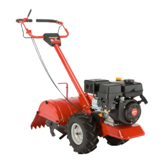
Controls & Features Reverse Handle Forward Clutch Bail & Tine Engagement Depth Regulator Handle Height Adjustment Side Shield Rear Tine Shield Tines Wheel Drive Pin Figure 4-1 Depth Regulator Lever NOTE: This Operator’s Manual covers several garden tiller models. The tiller depicted may differ from yours. This lever controls the tilling depth of the tines. -
Page 11: Operation
Operation WARNING! Starting the Engine Before operating your machine, carefully read and understand this manual and all of WARNING! To help prevent serious personal injury its safety, operating and maintenance sections and or damage to equipment, put both wheels in the instructions, along with all of the decals on the WHEEL DRIVE position. -
Page 12: Stopping The Engine
Stopping the Engine Setting The Depth To stop the wheels and tines, release the Forward Clutch Tilling depth is controlled by the depth stake which can be Bail. adjusted to five different settings. Adjust the side shields as you adjust the depth stake. Refer to the Engine Operator’s Manual for instructions on stopping the engine. - Page 13 Clearing the Tines • When cultivating (breaking up the surface soil around the plants to destroy weeds, see Fig. 5-3), adjust the tines to • The tines have a self-clearing action which eliminates most dig only 1” to 2” deep. Using the shallow tilling depth helps of the tangling of debris.
- Page 14 Suggested Tilling Patterns • If the garden size will not permit lengthwise and then crosswise tilling, then overlap the first passes by one-half • When preparing a seedbed, go over the same path twice in a tiller width, followed by successive passes at one-quarter the first row, then overlap one-half the tiller width on the width.
- Page 15 Terrace Gardening Loading & Unloading the Tiller To create a terrace, start at the top of the slope and work WARNING! Loading and unloading the tiller into a down. Go back and forth across the first row as shown in vehicle is potentially hazardous and doing so is not Fig.
-
Page 16: Maintenance & Adjustments
Maintenance & Adjustments Maintenance Schedule Check After Before each Every Every Every See Engine first 2 hours 5 Hours 10 Hours 30 Hours Manual Check Drive Belt Tension Check Nuts and Bolts Lubricate Tiller Check Gear Oil Level in Transmission Check Tines for Wear Check Air Pressure in Tires WARNING! - Page 17 Change Transmission Gear Oil • Remove the tines and clean the tine shaft. Use a file or sandpaper to gently remove any rust, burrs or rough spots NOTE: The transmission gear oil does not need to be changed (especially around the holes in the shaft). Apply grease to unless it has been contaminated with dirt, sand or metal the ends of the shaft before installing the tines.
-
Page 18: Service
Service Belt Replacement Remove the four 1/4-20 self-tapping hex screws that secure the pulley shield to the frame as seen in Fig. 7-2, and If the drive belt or auger belts need to be replaced, it is best remove the pulley shield and set aside in a safe location to replace both belts at the same time. - Page 19 Tines Remove the idler pulley bracket by removing the 5/16-24 hex head screw, flat washer and lock washer, as in Fig. 7-4. The tines will wear with use and should be inspected at the beginning of each tilling season and after every 30 operating hours.
-
Page 20: Troubleshooting
Troubleshooting Problem Cause Remedy Wheels/Tines will not turn 1. Improper use of controls. 1. Review Operation section. 2. Worn, broken, or mis-adjusted drive belt(s). 2. Replace or adjust belts. 3. Internal transmission wear or damage. 3. Contact local dealer or the factory. 4. -
Page 21: Replacement Parts
Replacement Parts Component Part Number and Description 754-04090 Forward Drive Belt 754-04091 Reverse Drive Belt 946-04506 Forward Drive Cable 946-04504 Reverse Drive Cable 642-04072 4-Point Tine Assembly (RH) 642-04071 4-Point Tine Assembly (LH) 711-0415 Clevis Pin, .375 x 1.75 714-04043 Bow-Tie Cotter Pin 934-04232 Wheels, 13 x 5 x 6... - Page 22 Notes...
- Page 23 10 — n ection oteS...
Need help?
Do you have a question about the 400 and is the answer not in the manual?
Questions and answers