czech sport aircraft PS-28 cruiser Operating Handbook
Hide thumbs
Also See for PS-28 cruiser:
- Maintenance manual (330 pages) ,
- Maintenance manual (342 pages) ,
- Operating handbook (38 pages)
Table of Contents
Advertisement
Quick Links
Pilot's Operating Handbook
Airplane Registration Number:
Airplane Serial Number:
This Pilot's Operating Handbook is
EASA approved under
Restricted Type Certificate No.:
Date: 2012-07-03
PS-POH-1-1-11
P
S
-
2
8
C
P
S
-
2
8
C
i
r
u
i
s
e
r
r
u
i
s
e
r
PH - VTA
C0487
EASA.A.546
P
S
-
2
8
C
r
u
i
s
e
r
P
S
-
2
8
C
r
u
i
s
e
r
Rev. No.: 1
Advertisement
Chapters
Table of Contents

Subscribe to Our Youtube Channel
Related Manuals for czech sport aircraft PS-28 cruiser


Summary of Contents for czech sport aircraft PS-28 cruiser
- Page 1 PS-POH-1-1-11 Pilot’s Operating Handbook Airplane Registration Number: PH - VTA Airplane Serial Number: C0487 This Pilot’s Operating Handbook is EASA approved under EASA.A.546 Restricted Type Certificate No.: Date: 2012-07-03 Rev. No.: 1...
- Page 2 PS-POH-1-1-11 Intentionally left blank Date: 2011-09-01 Rev. No.: -...
- Page 3 PS-POH-1-1-11 Czech sport aircraft a.s. Na Záhonech 1177/212, 686 04 Kunovice Czech Republic Website: www.czechsportaircraft.com E-mail: office@czechsportaircraft.com Phone: +420 576 514 034 (Sales Dept.) Fax: +420 576 519 394 Date: 2011-09-01 Rev. No.: -...
- Page 4 PS-POH-1-1-11 Intentionally left blank Date: 2011-09-01 Rev. No.: -...
- Page 5 RECORD OF REVISIONS PS-POH-1-1-11 RECORD OF REVISIONS Rev. Affected pages Revision name Approved Date BRS moved to i, v, vii, viii, 2-8, 2-12, EASA AFM Supplement, specification 3-14, 4-3, 4-5, 4-6, 4-11, Approval 21. 8. 2012 of engine speed at 4-12 10041100 airplane waiting...
- Page 6 PS-POH-1-1-11 Intentionally left blank Date: 2011-09-01 Rev. No.: -...
- Page 7 LIST OF EFECTIVE PAGES PS-POH-1-1-11 LIST OF EFFECTIVE PAGES Section Page Date Section Page Date 2012-07-3 2011-09-01 EASA approved 2011-09-01 2011-09-01 EASA approved 2-10 2011-09-01 2011-09-01 EASA approved 2-11 2011-09-01 2012-07- EASA approved 2-12 2012-07-03 2011-09-01 2012-07-3 viii 2012-07-03 EASA approved 2011-09-01 2011-09-01 EASA approved...
-
Page 8: Table Of Contents
LIST OF EFECTIVE PAGES PS-POH-1-1-11 LIST OF EFFECTIVE PAGES (Cont’d) Section Page Date Section Page Date 4-10 2011-09-01 EASA approved 6-12 2011-09-01 4-11 2012-07-3 EASA approved 6-13 2011-09-01 4-12 2012-07-3 EASA approved 6-14 2011-09-01 EASA approved 6-15 2011-09-01 EASA approved 6-16 2011-09-01 EASA approved... - Page 9 LIST OF ABBREVIATIONS PS-POH-1-1-11 LIST OF ABBREVIATIONS Attitude direction indicator Above Ground Level Altitude or Altimeter Air Traffic Control Airspeed Indicator Pressure unit (1 bar = 14.5037 psi) BEACON Anti-collision beacon °C Temperature in degree of Celsius (°C = (°F - 32) / 1.8) Calibrated Airspeed Course deviation indicator C.G.
- Page 10 LIST OF ABBREVIATIONS PS-POH-1-1-11 MTOW Maximum TakeOff Weight Vertical speed in meters per second (1 m/s = 196.8 fpm = 1.944 knots = 3.6 km/h) Newton - force unit (1 N = 0.225 lbf) Nautical mile (1 NM = 1,852 m) System is switched off or control element is in off-position System is switched on or control element is in on-position Outside Air Temperature...
- Page 11 CS-LSA STANDARDS PS-POH-1-1-11 CS-LSA STANDARD r aircraft is designed and built according to CS-LSA standard. CS-LSA, Initial Issue 27 June 2011 Certification Specification for Light Sport Aeroplanes Date: 2011-09-01 Rev. No.: -...
- Page 12 PS-POH-1-1-11 Intentionally left blank Date: 2011-09-01 Rev. No.: -...
-
Page 13: Contact Information
CONTACT INFORMATION PS-POH-1-1-11 CONTACT INFORMATION Czech Sport Aircraft a.s. Na Záhonech 1177/212, 686 04 Kunovice Czech Republic Website: www.czechsportaircraft.com E-mail: office@czechsportaircraft.com Phone: +420 576 514 034 (Sales Dept.) Fax: +420 576 519 394 Date: 2011-09-01 xiii Rev. No.: -... - Page 14 PS-POH-1-1-11 Intentionally left blank Date: 2011-09-01 Rev. No.: -...
- Page 15 TABLE OF CONTENTS PS-POH-1-1-11 TABLE OF CONTENTS 1. General Information 2. Limitations 3. Emergency Procedures 4. Normal Procedures 5. Performance 6. Weight and Balance 7. Description of Airplane and Systems 8. Handling and Servicing 9. Supplements Date: 2011-09-01 Rev. No.: -...
- Page 16 PS-POH-1-1-11 Intentionally left blank Date: 2011-09-01 Rev. No.: -...
- Page 17 SECTION 1 PS-POH-1-1-11 GENERAL INFORMATION SECTION 1 TABLE OF CONTENTS 1. GENERAL INFORMATION Airplane specification Summary of performances Date: 2011-09-01 Rev. No.: -...
- Page 18 SECTION 1 PS-POH-1-1-11 GENERAL INFORMATION 1. GENERAL INFORMATION This Pilot’s Operating Handbook (POH) has been prepared to provide pilots with information for the safe and efficient operation of the aircraft and contains 9 sections. It also contains supplementary information considered to be important by the aircraft manufacturer. Date of issue is written in the yy-mm-dd format.
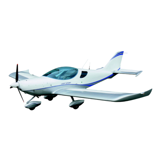
- Page 19 SECTION 1 PS-POH-1-1-11 GENERAL INFORMATION ircraft layout: Date: 2011-09-01 Rev. No.: -...
- Page 20 SECTION 1 PS-POH-1-1-11 GENERAL INFORMATION Main airplane dimensions: Wing span ............8.600 m Length............6.620 m Height ............2.315 m Wing area ............12.30 m Wing loading ..........49 kg/m Cockpit width ..........1.170 m Flight control surfaces travel: Rudder ............30° ±2° to each side Elevator ............+24° / -24° ±2° Aileron ............+15°...
- Page 21 SECTION 1 PS-POH-1-1-11 GENERAL INFORMATION 1.2 Summary of performances Weights: Max. takeoff and landing weight ....600 kg Max. weight of fuel .........82 kg Max. baggage weight in rear fuselage ...18 kg Max. baggage weight in each wing locker ..10 kg Empty weight (minimum equipment) ....374 kg +2% NOTE Actual empty weight is shown in Section 9, Supplement No.
- Page 22 SECTION 1 PS-POH-1-1-11 GENERAL INFORMATION Rate of climb: At sea level ............825 fpm Best angle of climb speed (v ) .......55 KIAS Best rate of climb speed (v ) ......62 KIAS Stall speeds: – flaps down, power - idle .......31 KIAS –...
-
Page 23: Easa Approved
SECTION 2 PS-POH-1-1-11 LIMITATIONS SECTION 2 TABLE OF CONTENTS 2. LIMITATIONS Airspeed indicator range markings Stalling speeds at maximum takeoff weight Flap extended speed range Manoeuvring speed Maximum structural cruising speed Never exceed speed Service ceiling Load factors Approved manoeuvres 2.10 Operating weights and loading 2.11 Fuel 2.12 Engine operating speeds and limits... -
Page 24: Limitations
SECTION 2 PS-POH-1-1-11 LIMITATIONS 2. LIMITATIONS CAUTION AVIATIK WA037383 pitot-static probe Airspeeds values are valid for standard 2.1 Airspeed indicator range markings NOTE The stated stall speeds are valid for all flight altitudes. Speeds value or range Significance Marking KIAS White 31-75 Flap Operating Range. -
Page 25: Flap Extended Speed Range
SECTION 2 PS-POH-1-1-11 LIMITATIONS NOTE Altitude losses shown in the table present max. values determined on the basis of flight tests using average piloting skill. 2.3 Flap extended speed range - V to V Flaps operating range ..........31 - 75 KIAS 2.4 Manoeuvring speed - V Manoeuvring speed at 600 kg .......... -
Page 26: Operating Weights And Loading
SECTION 2 PS-POH-1-1-11 LIMITATIONS 2.10 Operating weights and loading Max. takeoff weight ............600 kg Max landing weight ............600 kg Max. weight of fuel ............82 kg Max. baggage weight in rear fuselage ......18 kg Max. baggage weight in each wing locker ......10 kg Empty weight (minimum equipment) ......... -
Page 27: Fuel
SECTION 2 PS-POH-1-1-11 LIMITATIONS 2.11 Fuel Fuel quantity: Wing fuel tanks quantity ............ 2x 57 L Total fuel quantity ............. 114 L Unusable fuel ..............2x 0.5 L Total usable fuel ............... 113 L Maximum allowable difference in fuel tanks ...... 30 L Recommended fuel type: NOTE Refer to the ROTAX Operator’s Manual, section 2.4 Fuel, and Rotax Service... -
Page 28: Easa Approved
SECTION 2 PS-POH-1-1-11 LIMITATIONS 2.12 Engine operating speeds and limits Engine Model: ROTAX 912 S2 Engine Manufacturer: BRP-Powertrain GmbH Max. takeoff: at 5,800 rpm (max. 5 min.) 73.5 kW Max. continuous: at 5,500 rpm Power 69 kW Cruising (75%): at 5,000 rpm 51 kW Max. -
Page 29: Easa Approved
SECTION 2 PS-POH-1-1-11 LIMITATIONS 2.13 Engine instruments markings Normal Rotax 912 S2 Minimum Caution Caution Maximum Operating Limit Range Range Range 73.5 kW Range (red line) (yellow arc) (yellow arc) (red line) (98.6 hp) (green arc) Engine speed 0-1,400 5,500-5,800 5,800 1,400-5,500 0.8 bar... -
Page 30: Easa Approved
SECTION 2 PS-POH-1-1-11 LIMITATIONS • Minimum instruments and equipment list for Day VFR flights: • Airspeed indicator • Altimeter • Compass (is not required by CS-LSA) • Fuel quantity indicator • Tachometer (RPM) • Engine instruments as required by the engine manufacturer: Oil temperature indicator Oil pressure indicator Cylinder head temperature indicator... -
Page 31: Easa Approved
SECTION 2 PS-POH-1-1-11 LIMITATIONS 2.15 Limitation placards and markings Operating limitation on instrument panel AIRSPEEDS: 138 kts 88 kts 75 kts 31 kts WARNING! DO NOT EXCEED MAXIMUM 600kg/1320lbs TAKEOFF WEIGHT: WARNING! IFR FLIGHTS AND INTENTIONAL FLIGHTS UNDER ICING CONDITIONS ARE PROHIBITED APPROVED FOR: DAY - VFR FOR AVIATION EMERGENCY USE ONLY. -
Page 32: Miscellaneous Placards And Markings
SECTION 2 PS-POH-1-1-11 LIMITATIONS 2.16 Miscellaneous placards and markings PILOT MUSIC IN HEADSET COPILOT POWER CHOKE HEADSE IDLE CANOPY COCKPIT L C OPENED ALARM O L P O EFIS & EMS E S ALERTS VOLUME N E INSTR L ELT CONTROL PEDAL SETTING PEDAL SETTING Date: 2011-09-01... -
Page 33: Easa Approved
SECTION 2 PS-POH-1-1-11 LIMITATIONS FUEL CAPACITY: CANOPY OPENED 57 Litres / 15 US Gal. MOGAS RON 95/AKI 91 CANOPY CLOSED AVGAS 100 LL + 0.2 FUEL DRAIN AEROSHELL OIL + 0.1 SPORT PLUS 4 NO PUSH NO STEP CAUTION The owner (operator) of this airplane is responsible for the readability of placards during the aircraft service life. -
Page 34: Easa Approved
SECTION 2 PS-POH-1-1-11 LIMITATIONS Intentionally left blank Date: 2012-07-03 EASA approved Rev. No.: 1 2-12... - Page 35 SECTION 3 PS-POH-1-1-11 EMERGENCY PROCEDURES SECTION 3 TABLE OF CONTENTS 3. EMERGENCY PROCEDURES General information Airspeeds for Emergency procedures Engine failure during takeoff run Engine failure after takeoff Loss of engine power in flight In-flight engine starting Loss of oil pressure High oil pressure Emergency landing without engine power 3.10 Precautionary landing with engine power...
- Page 36 SECTION 3 PS-POH-1-1-11 EMERGENCY PROCEDURES 3.23 Loss of primary instruments 3-11 3.24 Loss of flight controls 3-12 3.25 Power lever linkage failure 3-12 3.26 Inadvertent canopy opening during takeoff 3-13 3.27 List of EMS alert alarms 3-14 Date: 2011-09-01 EASA approved Rev.
-
Page 37: Emergency Procedures
SECTION 3 PS-POH-1-1-11 EMERGENCY PROCEDURES 3. EMERGENCY PROCEDURES 3.1 General information This section provides checklists and amplified procedures for coping with various emergencies that may occur. Emergencies caused by aircraft or engine malfunction are extremely rare if proper pre-flight inspections and maintenance are practiced. -
Page 38: Engine Failure During Takeoff Run
SECTION 3 PS-POH-1-1-11 EMERGENCY PROCEDURES 3.3 Engine failure during takeoff run 1. THROTTLE - IDLE 2. Brakes - apply 3. Ignition Switch - OFF 3.4 Engine failure after takeoff 1. Airspeed - maintain 60 KIAS 2. Flaps - as necessary 3. -
Page 39: Loss Of Oil Pressure
SECTION 3 PS-POH-1-1-11 EMERGENCY PROCEDURES 6. THROTTLE - IDLE 7. Ignition Switch - hold START after engine is starting - BOTH After engine is running: 8. MASTER GEN - ON 9. AVIONICS - ON 10. FUEL P - OFF 11. Other switches - ON as necessary 3.7 Loss of oil pressure 1. -
Page 40: Emergency Landing Without Engine Power
SECTION 3 PS-POH-1-1-11 EMERGENCY PROCEDURES 3.9 Emergency landing without engine power Emergency landings are generally carried out in the case of engine failure and the engine cannot be re-started. 1. Airspeed - maintain 60 KIAS 2. Emergency landing area - chose suitable area without obstacles 3. -
Page 41: Engine Fire During Start
SECTION 3 PS-POH-1-1-11 EMERGENCY PROCEDURES NOTE Watch the chosen area steadily during precautionary landing. 3.11 Engine fire during start 1. FUEL selector - OFF 2. THROTTLE - MAX 3. Ignition Switch - OFF 4. MASTER BAT & GEN - OFF 5. -
Page 42: Electrical Fire In Flight
SECTION 3 PS-POH-1-1-11 EMERGENCY PROCEDURES 3.13 Electrical fire in flight 1. MASTER BAT & GEN - OFF 2. Other switches - OFF 3. CABIN HEATER - PUSH OFF 4. Ventilation - open 5. Emergency landing - perform according to 3.9 as soon as possible 3.14 Emergency descent 1. -
Page 43: Overvoltage
SECTION 3 PS-POH-1-1-11 EMERGENCY PROCEDURES 3.16 Overvoltage • Voltage value (on EMS screen) highlighted red and blinking, bringing up the alarm bar at the bottom of the EMS screen with message, triggering the external EMS warning light and audio alert. •... -
Page 44: Inadvertent Icing Encounter
SECTION 3 PS-POH-1-1-11 EMERGENCY PROCEDURES 3.18 Inadvertent icing encounter CAUTION Aircraft is approved to operate in VMC condition only! 1. Leave icing area - turn back or change altitude to reach area with higher outside air temperature. 2. CARBURETOR AIR - PULL HOT 3. -
Page 45: Engine Vibration
SECTION 3 PS-POH-1-1-11 EMERGENCY PROCEDURES If you fail to recover the engine power, land on the nearest airfield (if possible) or depending on the circumstances, perform a precautionary landing according to 3.10. 3.20 Engine vibration If any forced aircraft vibrations appear, it is necessary: 1. -
Page 46: Loss Of Flight Controls
SECTION 3 PS-POH-1-1-11 EMERGENCY PROCEDURES EMS unit malfunction or failure 1. EMS circuit breaker - ON 2. EMS switch - ON 3. Land as soon as practicable CAUTION Do not use maximum engine power without RPM indication! 3.24 Loss of flight controls Lateral control failure Use the Aileron Trim and Rudder for aircraft banking. -
Page 47: Inadvertent Canopy Opening During Takeoff
SECTION 3 PS-POH-1-1-11 EMERGENCY PROCEDURES 3.26 Inadvertent canopy opening during takeoff • During takeoff – aircraft rotation occurs, the canopy opens approximately 50 mm. • During climb and descent with airspeed at 60-75 KIAS, the canopy stays opened 50-80 mm. •... -
Page 48: List Of Ems Alert Alarms
SECTION 3 PS-POH-1-1-11 EMERGENCY PROCEDURES 3.27 List of EMS alert alarms HIGH RPM ALARM HIGH OIL PRESSURE ALARM LOW OIL PRESSURE ALARM HIGH OIL TEMPERATURE ALARM LOW OIL TEMPERATURE ALARM HIGH EGT 1 / 2 ALARM HIGH CHT 1 / 2 ALARM HIGH FUEL PRESSURE ALARM LOW FUEL PRESSURE ALARM HIGH VOLTAGE ALARM... - Page 49 SECTION 4 PS-POH-1-1-11 NORMAL PROCEDURES SECTION 4 TABLE OF CONTENTS 4. NORMAL PROCEDURES Preflight check Engine starting Taxiing Normal takeoff Climb Best angle of climb speed Best rate of climb speed Cruise Descend 4.10 Approach 4-10 4.11 Normal landing 4-10 4.12 Short field takeoff and landing procedures 4-11 4.13 Balked landing procedures...
-
Page 50: Normal Procedures
SECTION 4 PS-POH-1-1-11 NORMAL PROCEDURES 4. NORMAL PROCEDURES This section provides checklists and recommended procedures for normal operation of the aircraft. CAUTION AVIATIK WA037383 pitot-static probe Airspeeds values are valid for standard WOODCOMP KLASSIC 170/3/R These normal procedures are valid for standard three composite blades ground adjustable propeller. - Page 51 SECTION 4 PS-POH-1-1-11 NORMAL PROCEDURES Inspection Check List • Canopy - condition of attachment, cleanness • Check cockpit for loose objects Switches: • Ignition - OFF • MASTER BAT - ON • EMS - ON, check Battery voltage - check EMS screen functioning - check Fuel quantity indication •...
- Page 52 SECTION 4 PS-POH-1-1-11 NORMAL PROCEDURES • Nose gear - wheel, fairing and leg attachment, condition, pressure of tire • Engine cowling - condition • Propeller and spinner - condition • Engine mount and exhaust manifold - condition, attachment • Oil quantity - check (Before this check, ensure Ignition switch and MASTER BAT - OFF, open the oil tank and then turn the propeller by hand in direction of engine rotation...
-
Page 53: Engine Starting
SECTION 4 PS-POH-1-1-11 NORMAL PROCEDURES WARNING Physically check the fuel level before each takeoff to make sure you have sufficient fuel for the planned flight. WARNING In case of long-term parking it is recommended to turn the engine several times (Ignition switch - OFF!) by turning the propeller. -
Page 54: Taxiing
SECTION 4 PS-POH-1-1-11 NORMAL PROCEDURES CAUTION • The starter should be activated for a maximum of 10 sec, followed by 2 min pause for starter cooling. • As soon as engine runs, adjust throttle to achieve smooth running at approx. 2,500 rpm. -
Page 55: Normal Takeoff
SECTION 4 PS-POH-1-1-11 NORMAL PROCEDURES 4.4 Normal Takeoff 4.4.1 Engine run-up CAUTION The engine run-up should be performed with the aircraft heading upwind and not on a loose terrain (the propeller may suck grit which can damage the leading edges of blades). -
Page 56: Climb
SECTION 4 PS-POH-1-1-11 NORMAL PROCEDURES 4.4.2 Before takeoff NOTE Elevator and aileron trim position indicators are displayed on the EMS main screen. Only the smaller elevator trim position indicator is displayed on the EFIS main screen. Aileron trim tab position can be checked visually from cockpit by view to the right. NOTE EFIS and EMS main screens are shown in Section 9, Supplement No. -
Page 57: Best Angle Of Climb Speed
SECTION 4 PS-POH-1-1-11 NORMAL PROCEDURES WARNING Takeoff is prohibited if: • Engine is running unsteadily, roughly or with vibrations • Engine instrument values are beyond operational limi • Aircraft systems (e.g. brakes, flight controls or avionics) working incorrectly • Crosswind velocity exceeds permitted limits (see Section 5 Performance, 5.7 Demonstrated wind performance) 4.5 Climb 1. -
Page 58: Approach
SECTION 4 PS-POH-1-1-11 NORMAL PROCEDURES 4.10 Approach 1. Approach speed - 60 KIAS 2. THROTTLE - as necessary 3. Flaps - takeoff position (12°) 4. Trims - as necessary 5. Safety harness - fasten CAUTION It is not advisable to reduce the engine throttle control lever to minimum on final approach and when descending from very high altitude. -
Page 59: Short Field Takeoff And Landing Procedures
SECTION 4 PS-POH-1-1-11 NORMAL PROCEDURES 4.11.4 Engine shut down 1. THROTTLE - IDLE 2. Instruments - engine instruments within limits 3. Ignition Switch - OFF 4. Switches - OFF 5. MASTER BAT & GEN - OFF 6. FUEL selector - OFF CAUTION Rapid engine cooling should be avoided during operation. -
Page 60: Balked Landing Procedures
SECTION 4 PS-POH-1-1-11 NORMAL PROCEDURES 4.13 Balked landing procedures 1. THROTTLE - MAX (max. 5,800 rpm for max. 5 min, max. continuous power 5,500 rpm) 2. Airspeed - min. 60 KIAS 3. Flaps - takeoff position (12°) (max. airspeed for flaps using is 75 KIAS) 4. - Page 61 SECTION 5 PS-POH-1-1-11 PERFORMANCE SECTION 5 TABLE OF CONTENTS 5. PERFORMANCE Takeoff distances Landing distances Rate of climb Cruise speeds RPM setting and fuel consumption Airspeed indicator system calibration 5-10 Demonstrated wind performance 5-11 Date: 2011-09-01 EASA approved Rev. No.: -...
- Page 62 SECTION 5 PS-POH-1-1-11 PERFORMANCE 5. PERFORMANCE The presented data has been computed from actual flight tests with the aircraft and engine in good conditions and using average piloting techniques. If not stated otherwise, the performance stated in this section is valid for maximum takeoff weight 600 kg and under ISA conditions.
-
Page 63: Performance
SECTION 5 PS-POH-1-1-11 PERFORMANCE 5.1 Takeoff distances Conditions: - Altitude: 0 ft ISA - Engine power: max. takeoff - Flaps: 12° Takeoff distance over RUNWAY Takeoff run distance 50 ft (15 m) obstacle SURFACE 1,270 CONCRETE 1,499 GRASS 5.2 Landing distances Conditions: - Altitude: 0 ft ISA - Engine power: idle - Flaps: 30°... -
Page 64: Cruise Speeds
SECTION 5 PS-POH-1-1-11 PERFORMANCE 5.4 Cruise speeds Engine Fuel Altitude Airspeeds speed consumption KIAS KCAS KTAS in Hg 4,200 23.7 13.6 4,500 24.6 15.7 4,800 25.5 18.0 1,000 5,000 26.1 19.5 5,300 27.0 21.9 5,500 27.7 23.7 5,700 28.3 25.8 4,200 22.2 13.2... -
Page 65: Rpm Setting And Fuel Consumption
SECTION 5 PS-POH-1-1-11 PERFORMANCE 5.5 RPM setting and fuel consumption Altitude 1,000 Engine speed 4,200 4,500 4,800 5,000 5,300 5,500 Fuel consumption 13.6 15.7 18.0 19.5 21.9 23.7 KIAS Airspeeds KCAS KTAS Endurance and Range at 113 liters Endurance hh:mm 8:18 7:11 6:16... - Page 66 SECTION 5 PS-POH-1-1-11 PERFORMANCE Altitude 3,000 Engine speed 4,200 4,500 4,800 5,000 5,300 5,500 Fuel consumption 13.2 15.3 17.5 19.0 21.4 23.3 KIAS Airspeeds KCAS KTAS Endurance and Range at 113 liters Endurance hh:mm 8:33 7:23 6:27 5:56 5:16 4:50 Range 1142 1094...
- Page 67 SECTION 5 PS-POH-1-1-11 PERFORMANCE Altitude 5,000 Engine speed 4,200 4,500 4,800 5,000 5,300 5,500 Fuel consumption 12.9 14.9 17.2 18.7 21.1 22.8 KIAS Airspeeds KCAS KTAS Endurance and Range at 113 liters Endurance hh:mm 8:45 7:35 6:34 6:02 5:21 4:57 Range 1152 1110...
- Page 68 SECTION 5 PS-POH-1-1-11 PERFORMANCE Altitude 7,000 Engine speed 4,200 4,500 4,800 5,000 5,300 5,500 Fuel consumption 12.5 14.6 16.8 18.4 20.8 22.3 KIAS Airspeeds KCAS KTAS Endurance and Range at 113 liters Endurance hh:mm 9:02 7:44 6:43 6:08 5:25 5:04 Range 1155 1104...
- Page 69 SECTION 5 PS-POH-1-1-11 PERFORMANCE Altitude 9,000 Engine speed 4,200 4,500 4,800 5,000 5,300 5,500 Fuel consumption 12.2 14.3 16.4 18.0 20.4 21.8 KIAS Airspeeds KCAS KTAS Endurance and Range at 113 liters Endurance hh:mm 9:15 7:54 6:53 6:16 5:32 5:11 Range 1149 1083...
-
Page 70: Airspeed Indicator System Calibration
SECTION 5 PS-POH-1-1-11 PERFORMANCE 5.6 Airspeed indicator system calibration KIAS KCAS Date: 2011-09-01 EASA approved Rev. No.: - 5-10... -
Page 71: Demonstrated Wind Performance
SECTION 5 PS-POH-1-1-11 PERFORMANCE 5.7 Demonstrated wind performance Max. demonstrated headwind velocity for take-off and landing: ..24 knots Max. demonstrated crosswind velocity for take-off and landing: ..12 knots Wind components figure Example: 1. Wind velocity ..15 knots 3. Headwind component ..8.6 knots 2. - Page 72 SECTION 5 PS-POH-1-1-11 PERFORMANCE Intentionally left blank Date: 2011-09-01 EASA approved Rev. No.: - 5-12...
- Page 73 SECTION 6 PS-POH-1-1-11 WEIGHT & BALANCE SECTION 6 TABLE OF CONTENTS 6. WEIGHT AND BALANCE Introduction Airplane weighing procedure Operating weights and loading Weight and balance C.G. layout C.G. range and determination Loading and C.G. check Fuel weight – quantity conversion chart 6-11 C.G.
-
Page 74: Weight And Balance
SECTION 6 PS-POH-1-1-11 WEIGHT & BALANCE 6. WEIGHT AND BALANCE 6.1 Introduction This section contains weight and balance records and the payload range for safe operation of r aircraft. Procedures for weighing the aircraft and the calculation method for establishing the permitted payload range are contained in FAA Aviation Advisory Circular AC.43.13 –... -
Page 75: Operating Weights And Loading
SECTION 6 PS-POH-1-1-11 WEIGHT & BALANCE - Obtain measurement LN by measuring horizontally and parallel to the airplane center line, from center of nose wheel axle left sides, to the datum on the left wing. Repeat on right side and average the measurements. Using weights from item 3 and measurements from item 4 the airplane weight and C.G. -
Page 76: Weight And Balance C.g. Layout
SECTION 6 PS-POH-1-1-11 WEIGHT & BALANCE 6.4 Weight and balance C.G. layout 6.5 C.G. range and determination 6.5.1 Aircraft C.G. range: Empty weight C.G. range ........28.5 to 29.5 % of MAC 427.5 to 442.5 mm of MAC Operating C.G. range ......... 28 to 35 % of MAC 420 to 525 mm of MAC Date: 2011-09-01 EASA approved... - Page 77 SECTION 6 PS-POH-1-1-11 WEIGHT & BALANCE 6.5.2 Aircraft C.G. determination After any changes in equipment or if the aircraft weight is affected by any alternation or repair, a new weighing and C.G. determination perform as follows: Aircraft empty weight C.G. determination 1.
- Page 78 SECTION 6 PS-POH-1-1-11 WEIGHT & BALANCE Blank form of Weight & Balance record WEIGHT & BALANCE RECORD Empty weight C.G. determination table WEIGHT MOMENT ITEM kg mm RIGHT MAIN WHEEL LEFT MAIN WHEEL NOSE WHEEL negative arm Empty weight: Aircraft moment: C.G.
-
Page 79: Loading And C.g. Check
SECTION 6 PS-POH-1-1-11 WEIGHT & BALANCE 6.6 Loading and C.G. check Before flight is important to determine that the aircraft is loaded so its weight and C.G. location are within the allowable limits. Aircraft loading and C.G. determination perform as follows: 1. - Page 80 SECTION 6 PS-POH-1-1-11 WEIGHT & BALANCE Example of Loading and C.G. check Aircraft empty data: weight ........387.0 kg arm ........432.4 mm moment ....... 167,329.0 kg mm MAC ........1,500 mm Operating weights: pilot ........85.0 kg passenger ......65.0 kg baggage in cockpit ....
- Page 81 SECTION 6 PS-POH-1-1-11 WEIGHT & BALANCE Loading and C.G. check table – zero fuel WEIGHT MOMENT ITEM kg mm EMPTY AIRCRAFT 387.0 432.4 167,329.0 PILOT 85.0 59,500.0 PASSENGER 65.0 45,500.0 BAGGAGE 10.0 1,310 13,100.0 COMPARTMENT 10.0 6,000.0 WING LOCKERS FUEL IN TANKS C.G.
- Page 82 SECTION 6 PS-POH-1-1-11 WEIGHT & BALANCE Blank form of Loading and C.G. check WEIGHT & BALANCE RECORD Aircraft C.G. check table WEIGHT MOMENT ITEM kg mm EMPTY AIRCRAFT PILOT PASSENGER BAGGAGE 1,310 COMPARTMENT WING LOCKERS FUEL IN TANKS C.G. TOTAL % MAC NOTE: Empty weight is including oil, coolant, hydraulic fluid and unusable fuel.
-
Page 83: Fuel Weight - Quantity Conversion Chart
SECTION 6 PS-POH-1-1-11 WEIGHT & BALANCE 6.7 Fuel weight – quantity conversion chart 6.8 C.G. change in dependence of fuel quantity Date: 2011-09-01 EASA approved Rev. No.: - 6-11... -
Page 84: Load Sheet And Balance Chart
SECTION 6 PS-POH-1-1-11 WEIGHT & BALANCE 6.9 Load sheet and Balance chart This chart makes possible to perform loading and C.G. check before flight simply and quickly. The undermentioned example shows how to use this chart. Perform following steps: 1. Record Empty weight and Empty C.G. (% of MAC) to the table. 2. - Page 85 SECTION 6 PS-POH-1-1-11 WEIGHT & BALANCE Date: 2011-09-01 EASA approved Rev. No.: - 6-13...
- Page 86 SECTION 6 PS-POH-1-1-11 WEIGHT & BALANCE Blank form of Load sheet & Balance chart Date: 2011-09-01 EASA approved Rev. No.: - 6-14...
-
Page 87: Installed Equipment List
SECTION 6 PS-POH-1-1-11 WEIGHT & BALANCE 6.10 Installed equipment list NOTE Actual Installed equipment list is shown in Section 9, Supplement No. 02. Date: 2011-09-01 EASA approved Rev. No.: - 6-15... - Page 88 SECTION 6 PS-POH-1-1-11 WEIGHT & BALANCE Intentionally left blank Date: 2011-09-01 EASA approved Rev. No.: - 6-16...
- Page 89 SECTION 7 PS-POH-1-1-11 DESCRIPTION OF AIRPLANE AND SYSTEMS SECTION 7 TABLE OF CONTENTS 7. DESCRIPTION OF AIRPLANE AND SYSTEMS General Airframe Flight controls Instrument panel Engine Propeller Landing gear Baggage compartment Seats and safety harnesses 7.10 Canopy 7.11 Fuel system 7.12 Electrical system 7.13 Flight instruments and Avionics 7.14 Pitot-static system...
-
Page 90: Description Of Airplane And Systems
SECTION 7 PS-POH-1-1-11 DESCRIPTION OF AIRPLANE AND SYSTEMS 7. DESCRIPTION OF AIRPLANE AND SYSTEMS 7.1 General This section provides description and operation of the aircraft and its systems. r aircraft is a single-engine, all metal, low-wing monoplane of semi-monocoque structure with two side-by-side seats. The airplane is equipped with a fixed tricycle undercarriage with castering nose wheel. -
Page 91: Instrument Panel
SECTION 7 PS-POH-1-1-11 DESCRIPTION OF AIRPLANE AND SYSTEMS Elevator and aileron trim tabs are electrically actuated by buttons on the control stick. Elevator and aileron trim position indicators are displayed on the EMS main screen. Only the smaller elevator trim position indicator is displayed on the EFIS main screen. -
Page 92: Propeller
SECTION 7 PS-POH-1-1-11 DESCRIPTION OF AIRPLANE AND SYSTEMS Carburetor preheating The heated air is streaming from a heat exchanger to the carburetor through the airbox. The control lever is installed on the middle panel. Ignition switch Ignition switch must be on BOTH position to operate the engine. For safety remove the key when engine is not running. -
Page 93: Landing Gear
SECTION 7 PS-POH-1-1-11 DESCRIPTION OF AIRPLANE AND SYSTEMS 7.7 Landing gear Aircraft is equipped with tricycle landing gear. Main landing gear uses two fiberglass spring elements. Each main gear wheel is equipped with an independent, hydraulically operated, disc type brakes. Nose wheel is free castering. -
Page 94: Canopy
SECTION 7 PS-POH-1-1-11 DESCRIPTION OF AIRPLANE AND SYSTEMS 7.10 Canopy Access to the cabin is from both sides. Make sure that the canopy is latched and mechanism is securely locked into position on both sides before operating the aircraft and manually check the canopy is locked by pushing the canopy upward. -
Page 95: Electrical System
SECTION 7 PS-POH-1-1-11 DESCRIPTION OF AIRPLANE AND SYSTEMS CAUTION Do not overfill the tanks to avoid fuel overflow through venting tubes. 7.12 Electrical system Generator The AC generator (250 W AC) is integrated in the engine and it is connected to the electric bus through the external rectifier regulator (12 V 20 A DC). - Page 96 SECTION 7 PS-POH-1-1-11 DESCRIPTION OF AIRPLANE AND SYSTEMS Intentionally left blank Date: 2011-09-01 Rev. No.: -...
- Page 97 SECTION 8 PS-POH-1-1-11 HANDLING AND SERVICING SECTION 8 TABLE OF CONTENTS 8. HANDLING AND SERVICING Introduction Ground handling Towing instructions Tie-down instructions Servicing operating fluids Cleaning and care Assembly and disassembly Aircraft inspection periods Aircraft alterations or repairs Date: 2011-09-01 Rev.
-
Page 98: Handling And Servicing
SECTION 8 PS-POH-1-1-11 HANDLING AND SERVICING 8. HANDLING AND SERVICING 8.1 Introduction This section contains factory-recommended procedures for proper ground handling and servicing of the airplane. It also identifies certain inspection and maintenance requirements, which must be followed if the airplane is to retain that new-plane performance and dependability. -
Page 99: Towing Instructions
SECTION 8 PS-POH-1-1-11 HANDLING AND SERVICING 8.3 Towing instructions To handle the airplane on ground use the Tow Bar, or if pushing the airplane by hand, push on the aft fuselage, placing your hands over an area of skin supported by a bulkhead. CAUTION Do not push or pull on the propeller or on the control surfaces when towing. -
Page 100: Servicing Operating Fluids
SECTION 8 PS-POH-1-1-11 HANDLING AND SERVICING 8.5 Servicing operating fluids See appropriate chapters in the ROTAX engine Maintenance and Operator’s manuals and r aircraft Maintenance manual for more instructions. 8.5.1 Approved fuel grades and specifications Recommended fuel type: (refer to the ROTAX Operator’s manual section 2.4 Fuel, Rotax Service Instruction SI-912-016) MOGAS European standard... - Page 101 SECTION 8 PS-POH-1-1-11 HANDLING AND SERVICING Oil volume: Minimum ................3.3 L Maximum ................3.8 L 8.5.3 Approved coolant grades and specifications Recommended coolant type: (refer to the Rotax Operator’s manual section 2.2 Operating speeds and limits and section 2.3 Coolant, Rotax Installation manual section 12 Cooling system, Rotax Service Instruction SI-912-016) In principle, 2 different types of coolant are permitted: •...
-
Page 102: Cleaning And Care
SECTION 8 PS-POH-1-1-11 HANDLING AND SERVICING 8.6 Cleaning and care Use efficient cleaning detergents to clean the aircraft surface. Oil spots on the aircraft surface (except the canopy!) may be cleaned with petrol. The canopy may only be cleaned by washing it with a sufficient quantity of lukewarm water and an adequate quantity of detergents. -
Page 103: Aircraft Alterations Or Repairs
SECTION 8 PS-POH-1-1-11 HANDLING AND SERVICING 8.9 Aircraft alternations or repairs It is recommended to contact the airplane manufacturer prior to any alternations to the aircraft to ensure that the airworthiness of the aircraft is not violated. Always use only the original spare parts produced by the airplane (engine, propeller) manufacturer. - Page 104 SECTION 8 PS-POH-1-1-11 HANDLING AND SERVICING Intentionally left blank Date: 2011-09-01 Rev. No.: -...
- Page 105 SECTION 9 PS-POH-1-1-11 SUPPLEMENTS SECTION 9 TABLE OF CONTENTS 9. SUPPLEMENTS List of inserted supplements Inserted supplements Date: 2011-09-01 Rev. No.: -...
- Page 106 SECTION 9 PS-POH-1-1-11 SUPPLEMENTS 9. SUPPLEMENTS This section contains the appropriate supplements necessary to safely and efficiently operate the aircraft when equipped with various optional systems and equipment not provided with the standard airplane. 9.1 List of inserted supplements Suppl. Rev.
- Page 107 SECTION 9 PS-POH-1-1-11 SUPPLEMENT No. 2 Supplement No. 02 AIRCRAFT SPECIFICATION Dynon D100 EFIS equipment package In this Supplement No. 02 – the Weight & Balance & Equipment is shown for real S/N of the aircraft. PH - VTA Aircraft Registration number : C0487 Aircraft Serial Number : This Supplement must be attached to the POH during airplane operation.
- Page 108 SECTION 9 PS-POH-1-1-11 SUPPLEMENT No. 2 RECORD OF REVISIONS Rev. Affected pages Revision name Approved Date Date: 2013-08-22 Rev. No.: - of 10...
-
Page 109: Weight And Balance
SECTION 9 PS-POH-1-1-11 SUPPLEMENT No. 2 6. WEIGHT AND BALANCE 6.5 C.G. range and determination 6.5.2 Aircraft C.G. determination WEIGHT & BALANCE RECORD Empty weight C.G. determination table WEIGHT MOMENT ITEM kg mm RIGHT MAIN WHEEL LEFT MAIN WHEEL NOSE WHEEL negative arm Empty weight: Aircraft moment:... - Page 110 SECTION 9 PS-POH-1-1-11 SUPPLEMENT No. 2 6.9 Installed equipment list r aircraft • Rotax 912 ULS2 with airbox and thermostats • Woodcomp KLASSIC 170/3/R • Dynon D100 EFIS • Dynon D120 EMS • UMA Backup Airspeed indicator • UMA Backup Altimeter •...
- Page 111 SECTION 9 PS-POH-1-1-11 SUPPLEMENT No. 2 7. DESCRIPTION OF AIRPLANE AND SYSTEMS 7.4 Instrument panel Instrument panel layout Date: 2013-08-22 Rev. No.: - of 10...
- Page 112 SECTION 9 PS-POH-1-1-11 SUPPLEMENT No. 2 Description of instrumentation and controls in the cockpit Parking brake Vent-air outlet PTT / elevator trim / aileron Transponder trim buttons Cockpit light controller Switches Instrument light controller Ignition switch EFIS Intentionally left blank Cabin opened warning light Flaps control switch EMS alarm light...
- Page 113 SECTION 9 PS-POH-1-1-11 SUPPLEMENT No. 2 7.12 Electrical system Circuit breakers and switches master battery MASTER BAT - transceiver switch - intercom MASTER GEN master generator switch engine instruments switch - transponder AVIONICS switch - GPS FUEL P fuel pump switch NAV L navigation lights...
- Page 114 SECTION 9 PS-POH-1-1-11 SUPPLEMENT No. 2 7.13 Instruments and Avionics The aircraft is equipped with instruments as follows: EFIS - Dynon D100 Backup airspeed indicator - Winter Backup altimeter - UMA Magnetic compass CM24 EMS - Dynon D120 The aircraft is equipped with avionics as follows: Transceiver - Garmin GNC 255 Intercom - PS Engineering PM3000 Transponder - Garmin GTX328...
- Page 115 SECTION 9 PS-POH-1-1-11 SUPPLEMENT No. 2 7.13.1 EFIS & EMS screens Main EFIS screen Main EMS screen Date: 2013-08-22 Rev. No.: - of 10...
- Page 116 SECTION 9 PS-POH-1-1-11 SUPPLEMENT No. 2 8. HANDLING AND SERVICING 8.5 Servicing operating fluids 8.5.2 Approved oil grades and specifications Type of oil used by aircrafts manufacturer: AeroShell Oil Sport Plus 4 SAE: 10W-40, API: SL 8.5.3 Approved coolant grades and specifications Type of coolant used by aircrafts manufacturer: Specification: ASTM D 3306, VW TL 774C Mixture ratio coolant / water: 50/50 %...
- Page 117 SECTION 9 PS-POH-1-1-11 SUPPLEMENT No. 10 Supplement No. 10 Installation of Garmin GNC 255A NAV/COMM PH - VTA Aircraft Registration Number: C0487 Aircraft Serial Number: This Supplement must be attached to the POH when the Garmin GNC 255A NAV/COMM installed accordance with manufacturer's...
- Page 118 SECTION 9 PS-POH-1-1-11 SUPPLEMENT No. 10 RECORD OF REVISIONS Rev. Affected pages Revision name Approved Date Date: 2013-04-20 Rev. No.: - of 10...
- Page 119 SECTION 9 PS-POH-1-1-11 SUPPLEMENT No. 10 Chapter 1 – GENERAL INFORMATION The airplane is equipped with Garmin GNC 255A NAV / COMM device. The COM section of the GNC 255A NAV / COMM operates in the aviation voice band, from 118.000 to 136.975 MHz, in 25 kHz steps (default). For European operations, a Com radio configuration of 8.33 kHz steps is also available.
- Page 120 SECTION 9 PS-POH-1-1-11 SUPPLEMENT No. 10 4.16.2 Selecting a Com Frequency 1. C/N key - press to reach the Com radio function, if necessary 2. Large knob - turn to change the values in one MHz increments 3. Small knob - turn to change the values in 25 kHz or 8.33 kHz increments 4.
- Page 121 SECTION 9 PS-POH-1-1-11 SUPPLEMENT No. 10 3. ENT key - press after selecting the desired characters. Turn the Small knob to scroll through the list of waypoint types; waypoint Types with a “+” sign will have more frequencies for the same type. After selection, the selected waypoint and type will be remembered for 30 minutes.
- Page 122 SECTION 9 PS-POH-1-1-11 SUPPLEMENT No. 10 4.16.8 OBS Mode 1. OBS key - press; if annunciator above the key lights: 2. Large and Small knobs - adjust the Omni Bearing Selector 4.16.9 Power off 1. Power / Volume knob - rotate counter clockwise past the detent 2.
- Page 123 SECTION 9 PS-POH-1-1-11 SUPPLEMENT No. 10 Chapter 7 – DESCRIPTION OF AIRPLANE AND SYSTEMS 7.13 Instruments and Avionics Garmin GNC 255A NAV / COMM (Fig. 9-1) consists of a transmitter / receiver for VHF communication (COM) and a receiver for navigation information (NAV).
- Page 124 SECTION 9 PS-POH-1-1-11 SUPPLEMENT No. 10 The Com radio features an automatic squelch to reject many localized noise sources. You may override the squelch function by pressing the Power/Com Volume/Squelch knob. This facilitates listening to a distant station or setting the desired volume level.
- Page 125 SECTION 9 PS-POH-1-1-11 SUPPLEMENT No. 10 ENT Key Press the ENT key to save selected values, to confirm a prompt, or to save the Standby frequency. MON (Monitor) Key The MON (Monitor) key will engage the monitor function where the Standby frequency may be monitored while still listening to the Active frequency.
- Page 126 SECTION 9 PS-POH-1-1-11 SUPPLEMENT No. 10 Chapter 8 – HANDLING AND SERVICING 8.10 GNC 255A NAV / COMM troubleshooting Problem Possible Cause Action GNC 255A does not power No power to the GNC 255A Check power connections, breakers, and main avionic switch Faulty electrical wiring or Contact your dealer to...
- Page 127 SECTION 9 PS-POH-1-1-11 SUPPLEMENT No. 11 Supplement No. 11 12 V Socket Installation PH - VTA Aircraft Registration number: C0487 Aircraft Serial Number: This Supplement must be attached to the POH when the 12 V Socket is installed in accordance with the manufacturer's approved documentation. Information in this Supplement completes or replaces information in the basic POH for the below mentioned parts only.
- Page 128 SECTION 9 PS-POH-1-1-11 SUPPLEMENT No. 11 RECORD OF REVISIONS Rev. Affected pages Revision name Approved Date Date: 2013-07-04 Rev. No.: - of 4...
- Page 129 SECTION 9 PS-POH-1-1-11 SUPPLEMENT No. 11 Chapter 1 – GENERAL INFORMATION No change. Chapter 2 - LIMITATIONS 2.16 Miscellaneous placards and markings 12 V MAX. 2 A Chapter 3 – EMERGENCY PROCEDURES No change. Chapter 4 – NORMAL PROCEDURES 4.4 Normal Takeoff 4.4.2 Before takeoff NOTE...
- Page 130 SECTION 9 PS-POH-1-1-11 SUPPLEMENT No. 11 Chapter 5 – PERFORMANCE No change. Chapter 6 – WEIGHT AND BALANCE No change. Chapter 7 – DESCRIPTION OF AIRPLANE AND SYSTEMS 7.13 Instruments and Avionics 12 V Socket The airplane is equipped with a 12 V socket on the right side of the instrument panel designed to supply portable appliances.
Need help?
Do you have a question about the PS-28 cruiser and is the answer not in the manual?
Questions and answers