Konica Minolta bizhub c450 Service Manual
Hide thumbs
Also See for bizhub c450:
- Service manual (780 pages) ,
- Copy operations (608 pages) ,
- Network scanner operations (462 pages)
Table of Contents
Advertisement
Quick Links
Advertisement
Chapters
Table of Contents

Related Manuals for Konica Minolta bizhub c450


Summary of Contents for Konica Minolta bizhub c450
-
Page 1: Service Manual
SERVICE MANUAL THEORY OF OPERATION 2005.03 Ver. 1.0... -
Page 2: Safety And Important Warning Items
IMPORTANT NOTICE Because of possible hazards to an inexperienced person servicing this product as well as the risk of damage to the product, KONICA MINOLTA BUSINESS TECHNOLOGIES, INC. (hereafter called the KMBT) strongly recommends that all servicing be performed only by KMBT-trained service technicians. -
Page 3: Safety Warnings
[1] MODIFICATIONS NOT AUTHORIZED BY KONICA MINOLTA BUSINESS TECHNOLOGIES, INC. KONICA MINOLTA brand products are renowned for their high reliability. This reliability is achieved through high-quality design and a solid service network. Product design is a highly complicated and delicate process where numerous mechanical, physical, and electrical aspects have to be taken into consideration, with the aim of arriving at proper tolerances and safety factors. - Page 4 SAFETY AND IMPORTANT WARNING ITEMS [2] POWER PLUG SELECTION In some countries or areas, the power plug provided with the product may not fit wall outlet used in the area. In that case, it is obligation of customer engineer (hereafter called the CE) to attach appropriate power plug or power cord set in order to connect the product to the supply.
-
Page 5: Checkpoints When Performing On-Site Service
SAFETY AND IMPORTANT WARNING ITEMS [3] CHECKPOINTS WHEN PERFORMING ON-SITE SERVICE KONICA MINOLTA brand products are extensively tested before shipping, to ensure that all applicable safety standards are met, in order to protect the customer and customer engi- neer (hereafter called the CE) from the risk of injury. However, in daily use, any electrical equipment may be subject to parts wear and eventual failure. - Page 6 SAFETY AND IMPORTANT WARNING ITEMS Power Plug and Cord WARNING • When using the power cord set (inlet type) that came with this product, make sure the connector is securely inserted in the inlet of the product. When securing measure is provided, secure the cord with the fixture properly.
- Page 7 SAFETY AND IMPORTANT WARNING ITEMS Wiring WARNING • Never use multi-plug adapters to plug multiple power cords in the same outlet. If used, the risk of fire exists. • When an extension cord is required, use a specified one. Current that can flow in the extension cord is limited, so using a too long extension cord may result in fire.
- Page 8 SAFETY AND IMPORTANT WARNING ITEMS Ventilation CAUTION • The product generates ozone gas during operation, but it will not be harmful to the human body. If a bad smell of ozone is present in the following cases, ventilate the room. a.
- Page 9 SAFETY AND IMPORTANT WARNING ITEMS Work Performed with the Product Powered On WARNING • Take every care when making adjustments or performing an operation check with the product powered. If you make adjustments or perform an operation check with the external cover detached, you may touch live or high-voltage parts or you may be caught in moving gears or the timing belt, leading to a risk of injury.
- Page 10 SAFETY AND IMPORTANT WARNING ITEMS Safety Checkpoints WARNING • Check electrode units such as a charging corona unit for deterioration and sign of leakage. Current can leak, leading to a risk of trouble or fire. • Before disassembling or adjusting the write unit (P/H unit) incorporating a laser, make sure that the power cord has been disconnected.
-
Page 11: Handling Of Consumables
SAFETY AND IMPORTANT WARNING ITEMS Safety Checkpoints WARNING • Make sure that all screws, components, wiring, connec- tors, etc. that were removed for safety check and mainte- nance have been reinstalled in the original location. (Pay special attention to forgotten connectors, pinched cables, forgotten screws, etc.) A risk of product trouble, electric shock, and fire exists. - Page 12 SAFETY AND IMPORTANT WARNING ITEMS Handling of Service Materials CAUTION • Use only a small amount of cleaner at a time and take care not to spill any liquid. If this happens, immediately wipe it off. A risk of fire exists. •...
- Page 13 SAFETY AND IMPORTANT WARNING ITEMS [4] Used Batteries Precautions ALL Areas CAUTION Danger of explosion if battery is incorrectly replaced. Replace only with the same or equivalent type recommended by the manufacturer. Dispose of used batteries according to the manufacturer’s instructions. Germany VORSICHT! Explosionsgefahr bei unsachgemäßem Austausch der Batterie.
- Page 14 SAFETY AND IMPORTANT WARNING ITEMS [5] FUSE CAUTION Double pole / neutral fusing ATTENTION Double pôle / fusible sur le neutre. [6] LED Radiation Safety • This product is a copier which operates by means of a LED (light emitting diodes) expo- sure system.
-
Page 15: Warning Indications On The Machine
SAFETY AND IMPORTANT WARNING ITEMS WARNING INDICATIONS ON THE MACHINE Caution labels shown are attached in some areas on/in the machine. When accessing these areas for maintenance, repair, or adjustment, special care should be taken to avoid burns and electric shock. High temperature High voltage High voltage... - Page 16 SAFETY AND IMPORTANT WARNING ITEMS High voltage High voltage High voltage 4037P0C502DA S-15...
- Page 17 SAFETY AND IMPORTANT WARNING ITEMS High voltage 4037P0C503DA CAUTION: • You may be burned or injured if you touch any area that you are advised not to touch by any caution label. Do not remove caution labels. If any caution label has come off or soiled and therefore the caution cannot be read, contact our Service Office.
-
Page 18: Main Unit
SERVICE MANUAL THEORY OF OPERATION Main Unit 2005.03 Ver. 1.0... - Page 20 After publication of this service manual, the parts and mechanism may be subject to change for improvement of their performance. Therefore, the descriptions given in this service manual may not coincide with the actual machine. When any change has been made to the descriptions in the service manual, a revised version will be issued with a revision mark added as required.
-
Page 22: Table Of Contents
Theory of Operation Ver. 1.0 Mar. 2005 CONTENTS Outline System configuration....................1 Product specifications ..................... 3 Type ........................3 Functions ......................3 Types of Paper ...................... 4 Maintenance ......................4 Machine Specifications ..................4 Operating Environment ..................5 Built-in Controllers ....................5 Center cross section .................... - Page 23 Theory of Operation Ver. 1.0 Mar. 2005 10.3 Operation......................27 10.3.1 PC Drum Drive mechanism ................ 27 10.3.2 PC Drum Phase control ................27 10.3.3 PC Drum small amount rotation control............28 Charge Corona section ..................29 11.1 Operation......................30 11.1.1 PC Drum Charge Corona ON/OFF control ..........
- Page 24 Theory of Operation Ver. 1.0 Mar. 2005 14.3.6 Transfer Belt cleaning.................. 55 14.3.7 Transfer Belt Filming Cleaning Mechanism ..........56 14.3.8 2nd Image Transfer Roller cleaning ............58 14.3.9 Charge neutralization and separation of paper ........... 59 14.3.10 Detection of New Transfer Belt Unit ............60 14.3.11 ACS control ....................
- Page 25 Theory of Operation Ver. 1.0 Mar. 2005 Conveyance section ....................83 18.1 Composition ....................... 83 Registration Roller section ..................84 19.1 Composition ....................... 84 19.2 Drive ........................84 19.3 Operation......................85 19.3.1 Registration Roller control ................85 19.3.2 OHP detection .................... 86 Fusing section.......................
- Page 26 Theory of Operation Ver. 1.0 Mar. 2005 24.2 Parts Operated When the Power Switch and Auxiliary Power Button are turned ON ....................111 24.2.1 Parts operated when the Power Switch and Auxiliary Power Button are turned ON ................... 111 24.3 Counter control ....................112 24.3.1 Construction....................
-
Page 27: Theory Of Operation Ver. 1.0 Mar
Theory of Operation Ver. 1.0 Mar. 2005 Blank Page... -
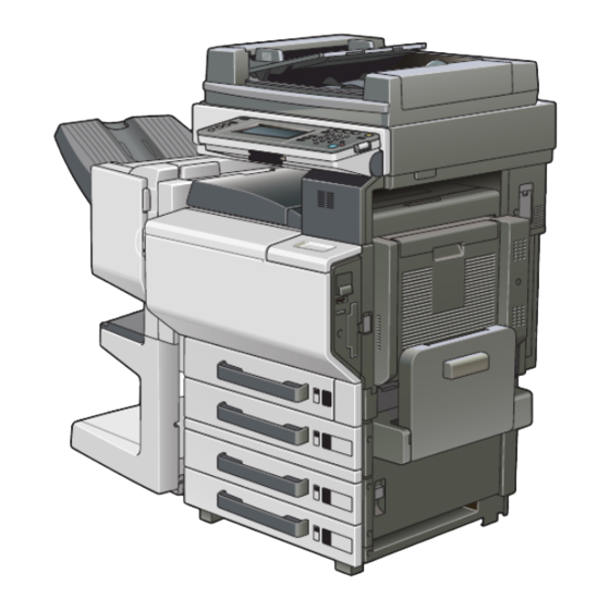
Page 28: System Configuration
Theory of Operation Ver. 1.0 Mar. 2005 1. System configuration Outline System configuration 1/2 System Front View [10] 4037F1C501DA Machine Paper Feed Cabinet PC-402 Working Table WT-501 Finisher FS-507 Paper Feed Cabinet PC-202 Job Separator JS-601 Paper Feed Cabinet PC-102 Finisher FS-603 Desk DK-501 [10] Punch Kit PK-501... - Page 29 1. System configuration Theory of Operation Ver. 1.0 Mar. 2005 2/2 System Rear View [10] PC-102 PC-202 DK-501 PC-402 4037F1E503DA Machine Image Controller IC-402 Fax Kit FK-502 Video Interface Kit VI-502 Mount Kit MK-703 Local Interface Kit EK-702 Mount Kit MK-704 Mechanical Counter MC-501 Dehumidifier Heater 1C [10] Key Counter Kit KIT-1...
-
Page 30: Product Specifications
Theory of Operation Ver. 1.0 Mar. 2005 2. Product specifications Product specifications Type Type Desktop-type printer integrated with scanner Copying System Electrostatic dry-powdered image transfer to plain paper Printing Process Tandem-type indirect electrostatic recording system PC Drum Type OPC (organic photo conductor) Scanning Density Equivalent to 600 dpi Exposure Lamp... -
Page 31: Types Of Paper
2. Product specifications Theory of Operation Ver. 1.0 Mar. 2005 Types of Paper Paper Source Tray1 Tray2 Multiple Bypass Plain paper ❍ ❍ ❍ (60 to 90 g/m / 16 to 24 lb Translucent paper – – – OHP transparencies (crosswise –... -
Page 32: Operating Environment
Theory of Operation Ver. 1.0 Mar. 2005 2. Product specifications Operating Environment Temperature 10 to 30 °C / 50 to 86° F (with a fluctuation of 10° C / 18° F or less per hour) Humidity 15 to 85 % (with a fluctuation of 20 %/h) Built-in Controllers Type Built-in type controller... -
Page 33: Center Cross Section
3. Center cross section Theory of Operation Ver. 1.0 Mar. 2005 Center cross section [10] 4037T1C501AA CCD Unit Multiple Bypass Fusing Unit Tray2 Imaging Unit/K Imaging Unit/M Imaging Unit/C Imaging Unit/Y Tray1 [10] Transfer Belt Unit... -
Page 34: Paper Path
Theory of Operation Ver. 1.0 Mar. 2005 4. Paper path Paper path 4036ma102c0... -
Page 35: Image Creation Process
5. Image creation process Theory of Operation Ver. 1.0 Mar. 2005 Image creation process [1] Photoelectric Conversion [2] IR Image Processing [10] Paper Separation [9] 2nd Image Transfer [11] Transfer Belt Cleaning [8] 1st Image Transfer [12] PC Drum Cleaning [4] PC Drum [13] Main Erase [7] Developing... - Page 36 Theory of Operation Ver. 1.0 Mar. 2005 5. Image creation process • The paper, which has undergone the 2nd image transfer process, is neu- [10] Paper Separation tralized so that it can be properly separated from the Transfer Belt by the Paper Separator Claws.
- Page 37 5. Image creation process Theory of Operation Ver. 1.0 Mar. 2005 Blank Page...
-
Page 38: Composition/Operation
Theory of Operation Ver. 1.0 Mar. 2005 6. Overall composition Composition/Operation Overall composition Timing chart at machine power up Main Motor (M1) Color PC Drum Motor (M5) Color Developing Motor(M6) K PC Motor (M7) Fusing Drive Motor (M2) Cleaning Brush Motor (M22) Developing Bias DC (Y/M/C) Charge Corona Bias (Color) Developing Bias DC (K) -
Page 39: Control Block Diagram
6. Overall composition Theory of Operation Ver. 1.0 Mar. 2005 Control block diagram Scanner Section CCD Sensor Exposure Lamp Board (PWB-A) Inverter Board (FL201) Scanner Motor Drive Board (PWB-IC) Image Processing Board (PWB-C) Scanner Motor (M201) DF-601 Panel Printer Section Copier Board (PWB-CF) MFP Control Board (PWB-MFP) Electronic sorting Board... -
Page 40: Scanner Section (Ir Section)
Theory of Operation Ver. 1.0 Mar. 2005 7. Scanner section (IR section) Scanner section (IR section) Composition 4036ma2501c0 4037T2C550AA Original Size Detection Sensor FD1 Scanner Motor (M201) Original Size Detection Sensor FD2 *2 Scanner Motor Drive Board (PWB-IC) Lens Original Cover Angle Sensor (PC202) CCD Unit *1 Mirror Unit... - Page 41 7. Scanner section (IR section) Theory of Operation Ver. 1.0 Mar. 2005 ∗1: CCD Unit Scanning Direction CCD Sensor 37.3 µm 37.3 µm Main Scanning Direction 9.325 µm 9.325 µm 4036ma2602c0 *2: Europe, China, Central America (220-240V Areas), North America Only. Countries other than the above-mentioned are standard settings...
-
Page 42: Drive
Theory of Operation Ver. 1.0 Mar. 2005 7. Scanner section (IR section) Drive Scanner Motor Exposure Unit Scanner Drive Cable/R Scanner Drive Cable/F Mirror Unit Scanner Home Sensor 4037T2C503AA Operation 7.3.1 Scan and Exposure Lamp control A. When the Power Switch is turned ON 1. - Page 43 7. Scanner section (IR section) Theory of Operation Ver. 1.0 Mar. 2005 B. When the Start key is pressed 1. The Exposure Lamp turns ON when the Start key is pressed. 2. The gain adjustment is made when the Exposure Unit moves past the point under the shading sheet.
-
Page 44: Original Size Detection Control
Theory of Operation Ver. 1.0 Mar. 2005 7. Scanner section (IR section) 7.3.2 Original Size Detection control A. Detection Method • For detection of the original size, the reflective size sensors detect the length of the orig- inal while the CCD detects the length of the original. •... - Page 45 7. Scanner section (IR section) Theory of Operation Ver. 1.0 Mar. 2005 Metric Area & China Areas Table 1 CCD Width (mm) Sensor ~153.0 ~187.0 ~200.0 ~215.0 ~225.0 ~261.5 ~275.0 278.1~` 16KR Table 2 Sensor CCD Width (mm) FD2* ~143 ~153 ~187 ~200 ~213 ~220.9 ~225 ~261.5 ~274.7 ~284.4 284.5~ Invoic Letter 16KR...
- Page 46 Theory of Operation Ver. 1.0 Mar. 2005 7. Scanner section (IR section) B. Detection Timing (When Placed on Original Glass) Validates the original length Validates the original size Original Size Sensors FD1 (PC203), and FD2 (PC204) Original Cover Angle Sensor (PC202) Exposure Lamp (FL201) Scanner Motor (M201) Size Reset Switch (SW201)
-
Page 47: Write Section (Ph Section)
8. Write section (PH section) Theory of Operation Ver. 1.0 Mar. 2005 Write section (PH section) Composition LED Unit 4037T2C504AA 4037T2C551AA SELFOC Lens PC Drum/Y, M, C, K LED Chips LED Assy/Y, M, C, K 4036ma2219c0... -
Page 48: Operation
Theory of Operation Ver. 1.0 Mar. 2005 8. Write section (PH section) Operation 8.2.1 Outline • Each of the PC Drums is irradiated with LED light and an electrostatic latent image is thereby formed. • The LED print head is a fixed scanning type exposure system that includes approx. 7,700 LED chips (600 dpi) arranged in the main scanning direction and a SELFOC lens array, or SLA that brings rays of light emitted by the LED chips to a focus on the surface of the PC Drum to form a full-size image. -
Page 49: Color Shift Correction System
8. Write section (PH section) Theory of Operation Ver. 1.0 Mar. 2005 8.2.2 Color Shift Correction System • In a tandem engine, in which an independent image reproduction process is provided for each of the four different colors of toner. Incorrect color registration, or color shift, is therefore more likely to occur due to each of the LED assemblies being out of correct position. -
Page 50: Imaging Unit Section (Iu Section)
Theory of Operation Ver. 1.0 Mar. 2005 9. Imaging Unit section (IU section) Imaging Unit section (IU section) Composition PC Drum/Y, M, C, K 4037T2C505AA 4037T2C552AA PC Drum/Y, M, C, K Cleaning Blade Toner Collecting Screw PC Drum Charge Corona /Y, M, C, K Developing Unit Main Erase Lamp/Y, M, C, K... -
Page 51: Drive
9. Imaging Unit section (IU section) Theory of Operation Ver. 1.0 Mar. 2005 Drive K PC Motor (M7) Developing Clutch/K (CL2) Color PC Drum Motor (M5) Color Developing Motor (M6) 4037T2C508AA 4037T2C507AA... -
Page 52: Operation
Theory of Operation Ver. 1.0 Mar. 2005 9. Imaging Unit section (IU section) Operation 9.3.1 IU Life control • Each IU has EEPROM that detects a new IU and keeps track of the service life of the IU. A. New IU detection •... -
Page 53: Photo Conductor Section
10. Photo Conductor section Theory of Operation Ver. 1.0 Mar. 2005 10. Photo Conductor section 10.1 Composition Charge Generating Layer (CGL) Charge Transport Layer (CTL) Aluminum Cylinder 4036ma2338c0 PC Drum/Y, M, C, K 4037T2C509AA Name Function/System • Forms an image of each of different colors. PC Drum/Y, M, C, K •... -
Page 54: Operation
Theory of Operation Ver. 1.0 Mar. 2005 10. Photo Conductor section 10.3 Operation 10.3.1 PC Drum Drive mechanism • Two independent PC Drum motors are used for the drive mechanism to suppress incor- rect color registration and uneven pitch. • The Color PC Drum Motor drives the PC Drums/Y, M, and C, while the K PC Motor drives the PC Drum/K. -
Page 55: Pc Drum Small Amount Rotation Control
10. Photo Conductor section Theory of Operation Ver. 1.0 Mar. 2005 10.3.3 PC Drum small amount rotation control • Humidity around the IU can produce a difference in sensitivity among different PC Drums. This could lead to drum memory, allowing black bands to occur in the image. In addition, ozone stagnant in areas near the PC Drum Charge Corona reduces sensitivity of the PC Drums, causing white bands to occur in the image. -
Page 56: Charge Corona Section
Theory of Operation Ver. 1.0 Mar. 2005 11. Charge Corona section 11. Charge Corona section Corona Wire Grid Mesh 4037T2C511AA 4037T2C552AA Grid Mesh Corona Wire Cleaning Lever 4037T2C512AA Cleaning Blade Corona Wire/Y, M, C, K Main Erase Lamp/Y, M, C, K (LA1 ~ LA2) 4037T2C506AA... -
Page 57: Operation
11. Charge Corona section Theory of Operation Ver. 1.0 Mar. 2005 11.1 Operation 11.1.1 PC Drum Charge Corona ON/OFF control • The grid voltage (Vg) applied to the Grid Mesh is controlled through the image stabiliza- tion control. Color PC Drum Motor Energized K PC Motor Energized Drum Charge Corona Bias Y, M, C Drum Charge Corona Bias K... -
Page 58: Developing Section
Theory of Operation Ver. 1.0 Mar. 2005 12. Developing section 12. Developing section 12.1 Composition Doctor Blade Developing Roller Supply/Agitating /Conveying Screws 4037T2C513AA 4037T2C552AA K PC Motor (M7) Developing Clutch/K (CL2) PC Drum/K Developing Roller Color PC Drum Motor (M5) Color Developing Motor (M6) Supply/Agitating /Conveying Screws... -
Page 59: Drive
12. Developing section Theory of Operation Ver. 1.0 Mar. 2005 12.2 Drive K PC Motor (M7) PC Drum/K Developing Clutch/K (CL2) Developing Roller Toner Collecting Screw Color Developing Motor (M6) Supply/Agitating /Conveying Screws Color PC Drum Motor (M5) 4037T2C515AA PC Drum/Y 4037T2C514AA... -
Page 60: Operation
Theory of Operation Ver. 1.0 Mar. 2005 12. Developing section 12.3 Operation 12.3.1 Developing Drive control Retraction Signal Main Motor ON Signal Printing DC AC *1 Developing Bias/Y, M, C Main Motor (M1) Color PC Drum Motor (M5) K PC Motor (M7) AC *1 Developing Bias/K Printing DC... -
Page 61: Developing Bias
12. Developing section Theory of Operation Ver. 1.0 Mar. 2005 12.3.3 Developing bias • The developing bias voltage (Vdc) is applied to the Developing Roller so that an ade- quate amount of toner is attracted onto the surface of the PC Drum. •... -
Page 62: Developer Scattering Preventive Mechanism
Theory of Operation Ver. 1.0 Mar. 2005 12. Developing section 12.3.5 Developer Scattering Preventive Mechanism • To prevent the image and the machine interior from being dirtied, the Toner Suction Fan Motor (M20) and Toner Suction Fan Motor/K (M23) are incorporated to trap toner parti- cles rising up inside the machine. - Page 63 12. Developing section Theory of Operation Ver. 1.0 Mar. 2005 B. IU/K • The system speed is high in the monochrome print mode and scattering developer can- not be removed if the same mechanism as that incorporated in the IU/YMC is used. A new fan motor and a new filter with a large capacity are installed instead of the filter orig- inally installed in the IU/K.
-
Page 64: Tcr Sensor Control
Theory of Operation Ver. 1.0 Mar. 2005 12. Developing section 12.3.6 TCR Sensor control • The TCR Sensor is mounted on the underside of each of the Developing Sections. The sensor for C, M, and Y is an optical type, while that for K is a magnetic type. Each of these sensors detects toner-to-carrier ratio (T/C) of the developer. - Page 65 12. Developing section Theory of Operation Ver. 1.0 Mar. 2005 TCR window bias • Since the optical TCR Sensor is used for C, M, and Y, a bias is applied to the TCR win- dow to prevent toner from sticking to it. No bias is applied to the TCR Sensor for K, which is the magnetic type.
-
Page 66: Toner Supply Section
Theory of Operation Ver. 1.0 Mar. 2005 13. Toner Supply section 13. Toner Supply section 13.1 Composition Cartridge/M Cartridge/K Cartridge/Y Cartridge/C 4037T2C553AA 4037T2C516AA Toner Set Sensor/C Toner Set Sensor/M Toner Set Sensor/K Toner Set Sensor/Y Toner Supply Motor Y/M (M4) Toner Supply Motor C/K (M3) 4037T2C517AA Toner Near-Empty Sensor PQ/Y, M, C, K... -
Page 67: Drive
13. Toner Supply section Theory of Operation Ver. 1.0 Mar. 2005 13.2 Drive Toner Supply Motor C/K (M3) Toner Supply Motor Y/M (M4) 4037T2C519AA Toner Near-Empty Sensor PQ/Y, M, C, K (PC15, PC16, PC17, PC18) Agitating Blade/Y, M, C, K Toner Near-Empty Sensor LED/Y, M, C, K (PC21, PC22, PC23, PC24) Metering Roller/Y, M, C, K... -
Page 68: Operation
Theory of Operation Ver. 1.0 Mar. 2005 13. Toner Supply section 13.3 Operation 13.3.1 Toner Replenishing mechanism/control A. Toner replenishing mechanism • Toner is supplied from the Toner Cartridge of each color to the Imaging Unit of each color according to the T/C detected by the corresponding TCR Sensor. •... -
Page 69: Toner Near-Empty And Toner Empty Detection Control
13. Toner Supply section Theory of Operation Ver. 1.0 Mar. 2005 13.3.2 Toner Near-Empty and Toner Empty detection control • A toner near-empty/empty condition is detected by the Toner Near-Empty Sensor PQ and LED mounted on each of the Toner Cartridges. •... -
Page 70: Shutter Mechanism
Theory of Operation Ver. 1.0 Mar. 2005 13. Toner Supply section 13.3.3 Shutter mechanism • To prevent toner from being spilled when the Toner Cartridge is removed from the machine, there is a shutter mechanism provided. When the Toner Cartridge is installed in the machine, the shutter opens. -
Page 71: Transfer Corona Section
14. Transfer Corona section Theory of Operation Ver. 1.0 Mar. 2005 14. Transfer Corona section 14.1 Composition 14.1.1 1st Image Transfer section Paper Separator Claws 4037T2C573AA 4037T2C554AA 1st Image Transfer Roller/M 1st Image Transfer Roller/K 1st Image Transfer Roller/C 1st Image Transfer Roller/Y Cleaning Brush Transfer Belt Drive Roller 4037T2C520AA... -
Page 72: 2Nd Image Transfer Section
Theory of Operation Ver. 1.0 Mar. 2005 14. Transfer Corona section 14.1.2 2nd Image Transfer section Temperature/Humidity Sensor (PC7) 4037T2C524AA 4037T2C555AA 2nd Image Transfer Roller 4037T2C522AA 2nd Image Transfer Roller 2nd Image Transfer Pressure/Retraction Sensor (PC29) 2nd Image Transfer Pressure/Retraction Motor (M13) IDC/Registration Sensor/2 (PC9) -
Page 73: Drive
14. Transfer Corona section Theory of Operation Ver. 1.0 Mar. 2005 14.2 Drive 14.2.1 1st Image Transfer section Transfer Belt Main Motor (M1) 4037T2C525AA 1st Image Transfer Roller/K 1st Image Transfer Roller/C 1st Image Transfer Roller/Y 1st Image Transfer Pressure/Retraction Motor (M11) 1st Image Transfer Roller/M 1st Image Transfer Retraction... -
Page 74: 2Nd Image Transfer Section
Theory of Operation Ver. 1.0 Mar. 2005 14. Transfer Corona section 14.2.2 2nd Image Transfer section 2nd Image Transfer Roller 2nd Image Transfer Pressure/ Retraction Sensor (PC29) 2nd Image Transfer Pressure/ Retraction Motor (M13) IDC/Registration Sensor/2 (PC9) Shutter Pressure Lever IDC/Registration Sensor/1 (PC8) 4037T2C523AA 14.3 Operation... -
Page 75: 1St Image Transfer Roller Mechanism
14. Transfer Corona section Theory of Operation Ver. 1.0 Mar. 2005 14.3.2 1st Image Transfer Roller mechanism • The machine is provided with a mechanism that presses the 1st Image Transfer Rollers up against the inside of the Transfer Belt during the 1st image transfer stage. The 1st Image Transfer Pressure/Retraction Motor (M11) provides the drive for this operation. - Page 76 Theory of Operation Ver. 1.0 Mar. 2005 14. Transfer Corona section B. Pressure position changing mechanism • To extend the service life of the PC Drum/Y, M, C, the pressure position of the 1st Image Transfer Roller is changed between the monochrome mode and the color mode. In the monochrome mode, the 1st Image Transfer Roller/Y, M, C is left in the retracted position and the PC Drum/Y, M, C is stopped.
- Page 77 14. Transfer Corona section Theory of Operation Ver. 1.0 Mar. 2005 C. Retraction mechanism • At the same time that the pressure position is changed, the Retraction Roller moves up and down to change the position of the image transfer on the surface of the Transfer Belt to suit the specific mode, either monochrome or color.
-
Page 78: 2Nd Image Transfer Roller Pressure Mechanism
Theory of Operation Ver. 1.0 Mar. 2005 14. Transfer Corona section 14.3.3 2nd Image Transfer Roller pressure mechanism • The machine is provided with a mechanism that presses the 2nd Image Transfer Roller up against, and retracts it from, the Transfer Belt to prevent the 2nd Image Transfer Roller from being dirtied due to patterns produced for purposes other than an actual copying operation, which may be a pattern produced during the image stabilization sequence or other function. -
Page 79: Idc Sensor Shutter Mechanism
14. Transfer Corona section Theory of Operation Ver. 1.0 Mar. 2005 • Operation Timing Start Key ON Paper moves past 2nd Image Transfer Roller Main Motor (M1) 2nd Image Transfer Pressure/ Retraction Motor (M13) 2nd Image Transfer Pressure/ Retraction Sensor (PC29) 4036ma2170c0 14.3.4 IDC Sensor Shutter mechanism... -
Page 80: Atvc (Auto Transfer Voltage Control)
Theory of Operation Ver. 1.0 Mar. 2005 14. Transfer Corona section 14.3.5 ATVC (Auto Transfer Voltage Control) • To optimize image transfer output, the machine is provided with ATVC control, or Auto Transfer Voltage Control. The control lets a constant current flow through each of the Image Transfer Rollers. - Page 81 14. Transfer Corona section Theory of Operation Ver. 1.0 Mar. 2005 D. 1st and 2nd image transfer ATVC operation timing • The 1st and 2nd image transfer ATVC operations are carried out immediately before the execution of image stabilization control. •...
-
Page 82: Transfer Belt Cleaning
Theory of Operation Ver. 1.0 Mar. 2005 14. Transfer Corona section 14.3.6 Transfer Belt cleaning • To scrape residual toner off the surface of the Transfer Belt, the Transfer Belt is provided with a Cleaning Brush and a Charging Brush. •... -
Page 83: Transfer Belt Filming Cleaning Mechanism
14. Transfer Corona section Theory of Operation Ver. 1.0 Mar. 2005 14.3.7 Transfer Belt Filming Cleaning Mechanism • A cleaning mechanism is provided for refreshing the surface of the Transfer Belt when filming occurs on the belt. • The cleaning section for the Transfer Belt is provided with a Cleaner, Belt Refresh Pad, and a Cleaning Brush. - Page 84 Theory of Operation Ver. 1.0 Mar. 2005 14. Transfer Corona section A. Operation • Loosening one screw provided at the Transfer Belt cleaning section will allow the Belt Refresh Pad to be pressed against the surface of the Transfer Belt. •...
-
Page 85: 2Nd Image Transfer Roller Cleaning
14. Transfer Corona section Theory of Operation Ver. 1.0 Mar. 2005 14.3.8 2nd Image Transfer Roller cleaning • To remove residual toner off the surface of the 2nd Image Transfer Roller, a +/- DC bias is applied alternately to the roller, thereby moving the residual toner to the surface of the Transfer Belt. -
Page 86: Charge Neutralization And Separation Of Paper
Theory of Operation Ver. 1.0 Mar. 2005 14. Transfer Corona section 14.3.9 Charge neutralization and separation of paper • To neutralize any charge potential left in the paper which has undergone the 2nd image transfer stage, a Charge Neutralizing Cloth is installed to the guide plate after the 2nd Image Transfer Roller. -
Page 87: Detection Of New Transfer Belt Unit
14. Transfer Corona section Theory of Operation Ver. 1.0 Mar. 2005 14.3.10 Detection of New Transfer Belt Unit • When a new Transfer Belt Unit is installed in the machine, the life counter is automatically cleared through new unit detection. •... -
Page 88: Acs Control
Theory of Operation Ver. 1.0 Mar. 2005 14. Transfer Corona section 14.3.11 ACS control • This machine adopts ACS control, which controls switching of the print mode according to the number of the continuous monochrome originals to achieve both a higher copying productivity and longer service life of the consumables. -
Page 89: Toner Collecting Section
15. Toner Collecting section Theory of Operation Ver. 1.0 Mar. 2005 15. Toner Collecting section 15.1 Composition IU Toner Collecting Screw 4037T2C556AA Waste Toner Bottle Transfer Belt Toner Collecting Screw 4037T2C527AA... -
Page 90: Drive
Theory of Operation Ver. 1.0 Mar. 2005 15. Toner Collecting section 15.2 Drive K PC Motor (M7) IU Toner Collecting Screw Cleaning Brush Motor (M22) Cleaning Brush Toner Collecting Roller Transfer Belt Toner Collecting Screw 4037T2C528AA... -
Page 91: Operation
15. Toner Collecting section Theory of Operation Ver. 1.0 Mar. 2005 15.3 Operation 15.3.1 Toner collecting mechanism • Toner collected by the Cleaning Brush of the Transfer Belt and waste toner in each of the Imaging Units are conveyed by the corresponding Toner Collecting Screws to the Waste Toner Bottle. -
Page 92: Waste Toner Near-Full/Full Detection Control
Theory of Operation Ver. 1.0 Mar. 2005 15. Toner Collecting section 15.3.3 Waste Toner Near-Full/Full detection control A. Waste toner near-full detection control • An optical sensor is used to detect waste toner. When the sensor is blocked for a given period of time, the machine determines that the Waste Toner Bottle is nearly full of waste toner. -
Page 93: Paper Feed Section
16. Paper feed section Theory of Operation Ver. 1.0 Mar. 2005 16. Paper feed section 16.1 Composition 16.1.1 Tray1 Tray1 Double Feed Sensor (PC1) Tray1 Paper Take-up Roller Tray1 Separator Roller 4037T2C530AA 4037T2C557AA Tray1 Paper Feed Clutch (CL1) Tray1 Set Sensor (PC14) Tray1 Double Feed Sensor (PC1) Tray1 Paper Near-Empty Sensor Tray1 Paper Empty Sensor (PC2) -
Page 94: Tray2
Theory of Operation Ver. 1.0 Mar. 2005 16. Paper feed section 16.1.2 Tray2 Tray2 Pick-up Roller Tray2 Separator Roller 4037T2C531AA Tray2 Vertical Transport Sensor (PC108) Vertical Transport Roller/2 Tray2 Paper Take-up Sensor (PC107) 4037T2C530AA Tray2 Paper Near-Empty Sensor (PC104) Tray2 Lift-up Motor (M101) Tray2 Vertical Transport Motor (M103) Tray2 Paper Feed Motor (M102) Tray2 Paper Take-up Sensor (PC107) -
Page 95: Drive
16. Paper feed section Theory of Operation Ver. 1.0 Mar. 2005 16.2 Drive 16.2.1 Tray1 Main Motor (M1) Tray1 Paper Take-up Roller Tray1 Paper Feed Clutch (CL1) 4037T2C533AA 16.2.2 Tray2 Tray2 Paper Feed Motor (M102) Vertical Transport Roller/2 Tray2 Paper Take-up Roller Tray2 Pick-up Roller Tray2 Lift-up Motor (M101) Paper Lifting Plate... -
Page 96: Operation
Theory of Operation Ver. 1.0 Mar. 2005 16. Paper feed section 16.3 Operation 16.3.1 Paper Take-up control (Tray1) Start Key ON Registration Roller ON Registration Roller ON Main Motor (M1) Tray1 Paper Feed Clutch (CL1) Intermediate Transport Motor (M14) Registration Roller Clutch (CL3) Registration Roller Sensor (PC28) 4036ma2121c0 16.3.2... -
Page 97: Paper Supply Level Detection Control
16. Paper feed section Theory of Operation Ver. 1.0 Mar. 2005 16.3.4 Paper supply level detection control • There is a window in the front cover of the cassette for indicating the paper supply level. • When the Paper Lifting Plate goes up, a red lever appears in the window. The lower the level of the paper stack, the more the red portion is visible. -
Page 98: Tray1 Paper Type Setting
Theory of Operation Ver. 1.0 Mar. 2005 16. Paper feed section 16.3.6 Tray1 paper type setting • The paper type is set from the control panel. Control is provided on the machine side dif- ferently as detailed below depending on the paper type setting made. System Heating Roller Set 1st Image... -
Page 99: Paper Size Detection Control
16. Paper feed section Theory of Operation Ver. 1.0 Mar. 2005 16.3.7 Paper size detection control • The width size (CD) and length size (FD) of the paper are detected. The paper size is determined based on the combination of these two sizes detected. A. - Page 100 Theory of Operation Ver. 1.0 Mar. 2005 16. Paper feed section Inch Area Tray1 Paper Size Board (PWB-I1) Tray1 CD Paper Size Paper Size Sensor (PC3) 5.5 × 8.5R 8.5 × 11 8.5 × 11R Executive Executive R 5.5 × 8.5 8.5×...
- Page 101 16. Paper feed section Theory of Operation Ver. 1.0 Mar. 2005 B. Tray2 Tray2 Paper Size Board (PWB-I2) Tray2 CD Paper Tray2 CD Paper Size Sensor/S Size Sensor/L Paper Size (PC101) (PC102) ON/OFF A5R *1 ON/OFF ON/OFF ON/OFF 5.5 × 8.5 *2 Letter Letter R Legal...
-
Page 102: Tray2 Paper Lifting Motion Control
Theory of Operation Ver. 1.0 Mar. 2005 16. Paper feed section 16.3.8 Tray2 paper lifting motion control A. When Tray2 is slid in • The paper lifting motion is started if the Tray2 Lift-up Sensor is unblocked with Tray2 slid in the machine. -
Page 103: Deceleration Control
16. Paper feed section Theory of Operation Ver. 1.0 Mar. 2005 16.3.9 Deceleration Control • When paper is fed from Tray2, Tray3, Tray4, LCC, or Bypass, the corresponding Trans- port Motor is controlled so that the period of time that begins when the paper take-up sequence is started and ends when the leading edge of the paper reaches the Registra- tion Roller becomes a predetermined value. -
Page 104: Bypass Section
Theory of Operation Ver. 1.0 Mar. 2005 17. Bypass section 17. Bypass section 17.1 Composition Bypass FD Paper Size Sensor/1 (PC111) Bypass FD Paper Size Sensor/2 (PC112) 4037T2C535AA Bypass FD Paper Size Sensor/3 (PC113) Bypass FD Paper Size Sensor/4 (PC114) 4037T2C558AA Bypass Paper Empty Sensor (PC110) Bypass Paper... -
Page 105: Drive
17. Bypass section Theory of Operation Ver. 1.0 Mar. 2005 17.2 Drive Bypass Paper Feed Clutch (CL101) Bypass Lift-up Sensor (PC115) Bypass Paper Pick-up Solenoid (SL101) 4037T2C537AA Bypass Lift-up Sensor (PC115) Bypass Paper Feed Clutch (CL101) Bypass Paper Take-up Roller Tray2 Vertical Transport Motor (M103) Bypass Paper Pick-up Solenoid (SL101) 4037T2C538AA... -
Page 106: Operation
Theory of Operation Ver. 1.0 Mar. 2005 17. Bypass section 17.3 Operation 17.3.1 Bypass Paper Take-up control Start Key ON Move to Standby Position Tray2 Vertical Transport Motor (M103) Bypass Paper Pick-up Solenoid (SL101) Bypass Lift-up Sensor (PC115) Bypass Paper Feed Clutch (CL101) Tray2 Vertical Transport Sensor (PC108) 4036ma2123c0 17.3.2... -
Page 107: Bypass Paper Lifting Motion Control
17. Bypass section Theory of Operation Ver. 1.0 Mar. 2005 17.3.3 Bypass Paper Lifting Motion Control • At the start of a Bypass paper take-up sequence, the Bypass Paper Pick-up Solenoid is energized to raise the Paper Lifting Plate so that the sheet of paper can be taken up. When the print cycle is completed, the Bypass Paper Pick-up Solenoid is energized again to return the Paper Lifting Plate to the standby position. -
Page 108: Paper Size Detection
Theory of Operation Ver. 1.0 Mar. 2005 17. Bypass section 17.3.4 Paper size detection • The size of the paper loaded in the Bypass Section is detected by the combination of ON or OFF positions of the four Bypass FD Paper Size Sensors and the Bypass Paper Size Unit. •... - Page 109 17. Bypass section Theory of Operation Ver. 1.0 Mar. 2005 Inch Area Bypass FD Bypass FD Bypass FD Bypass FD Bypass Paper Size Paper Size Paper Size Paper Size Paper Size Unit (VR1) Paper Size Sensor/1 Sensor/2 Sensor/3 Sensor/4 Detected Width (mm) (PC111) (PC112)
-
Page 110: Conveyance Section
Theory of Operation Ver. 1.0 Mar. 2005 18. Conveyance section 18. Conveyance section 18.1 Composition Transport Roller 4037T2C539AA 4037T2C559AA Intermediate Transport Motor (M14) Transport Roller 4037T2C540AA... -
Page 111: Registration Roller Section
19. Registration Roller section Theory of Operation Ver. 1.0 Mar. 2005 19. Registration Roller section 19.1 Composition Registration Roller Clutch (CL3) Paper Dust Remover Registration Roller 4037T2C541AA 4037T2C560AA OHP Sensor (PC27) 19.2 Drive Registration Roller Registration Roller Clutch (CL3) 4037T2C542AA... -
Page 112: Operation
Theory of Operation Ver. 1.0 Mar. 2005 19. Registration Roller section 19.3 Operation 19.3.1 Registration Roller control • A loop is formed in the paper between the Transport Roller and Registration Roller during the paper transportation to correct skewed paper feeding. The amount of the paper loop can be adjusted using "Loop Adjust"... -
Page 113: Ohp Detection
19. Registration Roller section Theory of Operation Ver. 1.0 Mar. 2005 19.3.2 OHP detection • To prevent failed prints of OHP film, whether or not the paper type fed through is a piece of OHP film is detected using the OHP Sensor. •... -
Page 114: Fusing Section
Theory of Operation Ver. 1.0 Mar. 2005 20. Fusing section 20. Fusing section 20.1 Composition Upper Paper Separator Claw 4037T2C543AA 4037T2C561AA Fusing Pressure Roller Thermistor (TH3) Heating Roller Thermostat (TS1) Heating Roller Pressure Roller Fusing Pressure Roller Heating Roller Heater Lamp (H3) Heater Lamp/2 (H2) Heating Roller Heater Lamp/1 (H1) -
Page 115: Drive
20. Fusing section Theory of Operation Ver. 1.0 Mar. 2005 20.2 Drive Fusing Pressure Roller Pressure/Retraction Motor (M19) Fusing Drive Motor (M2) Fusing Retraction Position Sensor (PC34) Fusing Pressure/Retraction Sensor (PC33) Pressure Roller 4037T2C545AA... -
Page 116: Operation
Theory of Operation Ver. 1.0 Mar. 2005 20. Fusing section 20.3 Operation 20.3.1 Fusing Roller drive control A. Speed change control • Drive for the Fusing Unit is provided by the Fusing Drive Motor. • To prevent poor fusing performance, the speed of the Fusing Drive Motor is changed in three steps according to the type of paper used and the copy mode. - Page 117 20. Fusing section Theory of Operation Ver. 1.0 Mar. 2005 1. The fusing speed in the beginnings is set to the higher speed, thereby forming a loop in the paper between the 2nd Image Transfer Roller and the Fusing Roller. 2.
-
Page 118: Fusing Roller Pressure/Retraction Mechanism
Theory of Operation Ver. 1.0 Mar. 2005 20. Fusing section 20.3.2 Fusing Roller pressure/retraction mechanism • To ensure prolonged durability of the Fusing Belt, the Pressure Roller is retracted from the Fusing Belt during any time other than a print cycle. (The roller is, however, retracted during a print cycle using envelopes.) •... -
Page 119: Fusing Temperature Control
20. Fusing section Theory of Operation Ver. 1.0 Mar. 2005 20.3.3 Fusing temperature control • The surface temperatures of the Heating Roller and Pressure Roller are detected using thermistors and the corresponding Heater Lamps are turned ON or OFF as necessary to maintain the set fusing temperature. - Page 120 Theory of Operation Ver. 1.0 Mar. 2005 20. Fusing section A. Warm-up • Four different types of warm-up control are employed for varying the set temperature of each roller, thereby preventing fusing performance from being degraded due to environ- mental changes. •...
- Page 121 20. Fusing section Theory of Operation Ver. 1.0 Mar. 2005 B. During a copy cycle • To achieve the intended level of fusing performance, the set temperature of each roller is varied according to the paper type. Heating Roller Set Pressure Roller Set Paper Type Temperature (°C)
-
Page 122: Protection Against Abnormal Conditions
Theory of Operation Ver. 1.0 Mar. 2005 20. Fusing section 20.3.4 Protection against abnormal conditions • The machine provides protection against abnormally high temperature of the Fusing Unit in the following three steps. ° 1. When the Heating Roller Thermistor/1 detects 245 C, or the Fusing Pressure °... -
Page 123: Detection Of A New Fusing Unit
20. Fusing section Theory of Operation Ver. 1.0 Mar. 2005 20.3.5 Detection of a New Fusing Unit • When a new Fusing Unit is installed in the machine, the life counter is automatically cleared through the machine’s capability of detecting a new Fusing Unit. •... -
Page 124: Wait Control While Using Ohp Or Thick Paper
Theory of Operation Ver. 1.0 Mar. 2005 20. Fusing section 20.3.7 Wait Control While Using OHP or Thick Paper • When using OHP (OHP interleaves), thick papers 1, 2 and 3, a control system is pro- vided to delay printing operation until the fusing temperature reaches the print control temperature as the exit roller marks are imprinted on the papers if the papers pass immediately after standby temperature control. -
Page 125: Paper Exit Section
21. Paper exit section Theory of Operation Ver. 1.0 Mar. 2005 21. Paper exit section 21.1 Composition Paper Exit Roller/2 4037T2C546AA 4037T2C562AA Charge Neutralizing Brush Paper Exit Roller/1 Paper Exit Roller/2 Exit Sensor (PC30) 4037T2C547AA... -
Page 126: Drive
Theory of Operation Ver. 1.0 Mar. 2005 21. Paper exit section 21.2 Drive Switchback Motor (M1-DU) Paper Exit Roller/1 Paper Exit Roller/2 4037T2C548AA... -
Page 127: Image Stabilization Control
22. Image stabilization control Theory of Operation Ver. 1.0 Mar. 2005 22. Image stabilization control 22.1 Overview • The machine provides the following image stabilization control to ensure stabilized copy image. Purpose Control Control Means • IDC intensity control • Max. density control To stabilize image density IDC Sensor •... -
Page 128: Operation
Theory of Operation Ver. 1.0 Mar. 2005 22. Image stabilization control 22.2 Operation 22.2.1 IDC Sensor LED intensity control • Controls changes in characteristics due to change with time and contamination of the IDC Sensor, part-to-part variations in the sensors, and change of environment. •... -
Page 129: Operation Flow
22. Image stabilization control Theory of Operation Ver. 1.0 Mar. 2005 22.4 Operation flow Mode 1 Mode 2 Mode 3 Mode 4 Mode 5 IDC intensity IDC intensity IDC intensity IDC intensity control control control control Max. density control 1 Max. -
Page 130: Image Processing
Theory of Operation Ver. 1.0 Mar. 2005 23. Image processing 23. Image processing 23.1 Scanner section image processing block diagram 1. Photoelectric conversion CCD Sensor Board 2. Analog-to-digital conversion 3. Shading correction Image Processing Board 4. Line-to-line variation correction 5. Zoom/movement processing 6. - Page 131 23. Image processing Theory of Operation Ver. 1.0 Mar. 2005 • The following detail the image processing operations performed by the Scanner Section. 1. A reduction type CCD Sensor is used to read the light reflected off the original and convert the optical data to a corresponding electric signal.
-
Page 132: Write Section Image Processing Block Diagram 1
Theory of Operation Ver. 1.0 Mar. 2005 23. Image processing 23.2 Write section image processing block diagram 1 From Scanner Section 2. Color correction processing (reflection/density conversion, 1. Image area discrimination masking, UCR/BP) 3. Miscellaneous processing (improved reproduction of black text, edge emphasis, edge expansion, smoothing, color balance, and gamma correction) 4. - Page 133 23. Image processing Theory of Operation Ver. 1.0 Mar. 2005 • The following detail the image processing operations performed by MFP Control Board on the Write Section. 1. Each image area, whether it is a color edge area, black edge area, dot area, or a continuous gradation area, is discriminated to optimize edge emphasis and smoothing just right for the image.
-
Page 134: Write Section Image Processing Block Diagram 2
Theory of Operation Ver. 1.0 Mar. 2005 23. Image processing 23.3 Write section image processing block diagram 2 From the MFP Control Board 20. High-speed LED drive 21. High-speed LED drive LED Drive Board 22. Intensity correction To each LED Unit 20. -
Page 135: Other Control
24. Other control Theory of Operation Ver. 1.0 Mar. 2005 24. Other control 24.1 Fan control 24.1.1 Construction Paper Cooling Fan Motor (M26) Fusing Cooling Fan Motor/1 (M9) Scanner Cooling Fan Motor (M202) Fusing Cooling Fan Motor/3 (M16) Cooling Fan Motor/2 (M10) Draws outside air in Toner Suction... -
Page 136: Operation
Theory of Operation Ver. 1.0 Mar. 2005 24. Other control 24.1.2 Operation A. Fan control Motor Name Paper Passage Mode Control Conditions • Turns at full speed when the Color PC Drum Motor (M5) or K PC Motor (M7) is energized Power Supply Cooling –... - Page 137 24. Other control Theory of Operation Ver. 1.0 Mar. 2005 Motor Name Paper Passage Mode Control Conditions • Turns at full speed if the machine interior ° temperature exceeds 16 C when the Main Motor (M1) is energized and the Exit Sen- sor (PC30) is activated •...
-
Page 138: Are Turned On
Theory of Operation Ver. 1.0 Mar. 2005 24. Other control 24.2 Parts Operated When the Power Switch and Auxiliary Power Button are turned ON 24.2.1 Parts operated when the Power Switch and Auxiliary Power Button are turned ON • When the Auxiliary Power Button is turned ON, the Control Board detects it and sends a control signal to the DC Power Supply. -
Page 139: Counter Control
24. Other control Theory of Operation Ver. 1.0 Mar. 2005 24.3 Counter control 24.3.1 Construction Mechanical Counter Total Counter (option) PWB-MFPC Key Counter (option) Electronic Counter PWB-SIF 4037T2C581AA Name Function/System • Shows the cumulative number of copies made in all copy modes Total Counter •... - Page 140 SERVICE MANUAL THEORY OF OPERATION Automatic Document Feeder 2005.03 Ver. 1.0...
- Page 142 After publication of this service manual, the parts and mechanism may be subject to change for improvement of their performance. Therefore, the descriptions given in this service manual may not coincide with the actual machine. When any change has been made to the descriptions in the service manual, a revised version will be issued with a revision mark added as required.
- Page 144 Theory of Operation Ver. 1.0 Mar. 2005 CONTENTS Outline Product specification ....................1 Type ........................1 Functions ......................1 Paper type ......................1 Paper feed prohibited originals ................2 Paper feed not guaranteed originals..............2 Mixed original feed chart..................3 Machine specifications..................
- Page 145 Theory of Operation Ver. 1.0 Mar. 2005 Blank Page...
-
Page 146: Product Specification
Theory of Operation Ver. 1.0 Mar. 2005 1. Product specification Outline Product specification Type Name Duplexing Document Feeder Paper Take-Up Paper Take-Up from top of stack Transport Endless Belt Transport Mode Type Turnover Loop Turnover Mode U-turn Turnover + Switchback U-Turn Turnover Paper Exit Mode (only in 1-Sided Mode) Installation... -
Page 147: Paper Feed Prohibited Originals
1. Product specification Theory of Operation Ver. 1.0 Mar. 2005 Paper feed prohibited originals • If fed, trouble occurrence will be highly possible. Type of Original Possible Trouble Sheets stapled or clipped together Take-up failure, damaged sheet, defective drive mechanism due to jammed staples or clips Sheets glued together Take-up failure, damaged sheet Take-up failure, Sheets misfed... -
Page 148: Mixed Original Feed Chart
Theory of Operation Ver. 1.0 Mar. 2005 1. Product specification Mixed original feed chart For Metric Max. Original 297 mm 257 mm 210 mm 182 mm 148 mm Size Mixed Original Size 297 mm 257 mm 210 mm 182 mm 148 mm For Inch Max. -
Page 149: Paper Feed Path
2. Paper Feed Path Theory of Operation Ver. 1.0 Mar. 2005 Paper Feed Path 1-Sided Mode 4582t1c002aa 1st side scanned) 1: Document feed ( 2: Conveyance, Reverse 3: Document exit 2-Sided Mode 4582t1c003aa 1st side scanned) 2nd side scanned) 1: Document feed ( 2: Conveyance, Reverse ( 3: Document exit... -
Page 150: Composition/Operation
Theory of Operation Ver. 1.0 Mar. 2005 3. Composition Composition/Operation Composition Switchback section Document feed section Document exit section 4582t1c001aa Reverse section Conveyance section... -
Page 151: Drive
4. Drive Theory of Operation Ver. 1.0 Mar. 2005 Drive Exit Motor (M3-DF) Transport Motor (M2-DF) Registration Clutch (CL1-DF) Take-Up Motor (M1-DF) 4582M601AA Exit Gate (drives by SL2-DF) Exit Switch Gate (drives by spring) Turnover Gate (drives by SL1-DF) 4582t2c002aa Exit Solenoid (SL2-DF) Turnover Solenoid (SL1-DF) -
Page 152: Operation
Theory of Operation Ver. 1.0 Mar. 2005 5. Operation Operation Document pick-up mechanism • The Document Pick-Up Section consists of the Document Stoppers, Pick-Up Rollers, Take-Up Roller and Separation Roller, and this section is driven by the Take-Up Motor. • The Pick-Up Rollers stay at their upper position during the standby state and are lowered when taking-up an original. -
Page 153: Document Take-Up/Transport Mechanism
5. Operation Theory of Operation Ver. 1.0 Mar. 2005 Document take-up/transport mechanism • The Pick-Up and Take-Up Rollers are rotated by the Take-Up Motor and an original is taken-up and transported to the Registration Roller. • Then, the original is transported onto the Original Glass by the Registration Roller driven by the Take-Up Motor, and the Transport Belt driven by the Transport Motor. - Page 154 Theory of Operation Ver. 1.0 Mar. 2005 5. Operation A. Document take-up operation flow Registration Clutch: ON ↓ Take-Up Motor: Forward Rotation ↓ Pick-Up Rollers go down and rotated via timing belt & gears ↓ At the same time, Document Stoppers go up ↓...
-
Page 155: Document Exit Mechanism
5. Operation Theory of Operation Ver. 1.0 Mar. 2005 Document exit mechanism 5.3.1 1-sided mode • The original transported by the Transport Belt is sent to the switchback section and then ejected onto the Exit Tray with its face-down in order to keep the original pages in proper order. -
Page 156: Exit Operation Flow
Theory of Operation Ver. 1.0 Mar. 2005 5. Operation 5.3.3 Exit operation flow A. Document exit motion in 1-sided mode Exit Motor: Forward Rotation ↓ Transport Motor: Forward Rotation ↓ The original is transported to the switchback section. ↓ Transport Motor: OFF after the original leaves from the Transport Belt ↓... -
Page 157: Turnover Mechanism (2-Sided Mode)
5. Operation Theory of Operation Ver. 1.0 Mar. 2005 Turnover mechanism (2-sided mode) • In the 2-Sided Mode, an original which has its 1st side scanned is turned-over and then transported to the scan position again for the 2nd side scanning. Turnover Gate Turnover Solenoid (SL1-DF) Exit Motor (M3-DF) -
Page 158: Raised/Lowered Position Detecting Mechanism
Theory of Operation Ver. 1.0 Mar. 2005 5. Operation Raised/lowered position detecting mechanism 5.5.1 Document size detection • The 20 degree Open Detection Mechanism enables the main unit to detect the document size when the DF is used as the Original Cover of the main unit, there is the Lever Actu- ator provided in the DF body that blocks or unblocks a sensor to initiate a reconfirmation of the original size as read by the original size detection sensors. - Page 159 5. Operation Theory of Operation Ver. 1.0 Mar. 2005 Blank Page...
-
Page 160: Automatic Duplex Unit
SERVICE MANUAL THEORY OF OPERATION Automatic Duplex Unit 2005.03 Ver. 1.0... - Page 162 After publication of this service manual, the parts and mechanism may be subject to change for improvement of their performance. Therefore, the descriptions given in this service manual may not coincide with the actual machine. When any change has been made to the descriptions in the service manual, a revised version will be issued with a revision mark added as required.
- Page 164 Theory of Operation Ver. 1.0 Mar. 2005 CONTENTS Outline Product specifications ..................... 1 Type ........................1 Paper type ......................1 Machine specifications..................1 Operating environment ..................1 Paper Feed Path ..................... 2 Composition/Operation Composition ......................3 Drive ........................4 Switchback Drive ....................4 Transport Drive .....................
- Page 165 Theory of Operation Ver. 1.0 Mar. 2005 Blank Page...
-
Page 166: Product Specifications
Theory of Operation Ver. 1.0 Mar. 2005 1. Product specifications Outline Product specifications Type Name Duplex Unit Type Switchback and Circulating Duplex Unit Installation Mounted on the right side door of main unit Document Alignment Center Paper type Paper Type Plain paper 60 to 256 g/m (16 to 68 lb) -
Page 167: Paper Feed Path
2. Paper Feed Path Theory of Operation Ver. 1.0 Mar. 2005 Paper Feed Path Switchback to Main Unit paper is fed into the main unit again 4535tm1c002aa... -
Page 168: Composition/Operation
Theory of Operation Ver. 1.0 Mar. 2005 3. Composition Composition/Operation Composition Switchback section Transport section 4535M001AA... -
Page 169: Drive
4. Drive Theory of Operation Ver. 1.0 Mar. 2005 Drive Switchback Drive Switchback Motor (M1-DU) Main Unit Duplex Unit Paper Exit Roller (Main Unit) 4535tm2c001aa Transport Drive Duplex Unit Transport Roller 1 Duplex Unit Transport Roller 2 Duplex Control Board (PWB-A DU) Duplex Unit Transport Roller 3 4535M004AA Duplex Unit Transport Motor (M2-DU) -
Page 170: Operation
Theory of Operation Ver. 1.0 Mar. 2005 5. Operation Operation Switchback mechanism 5.1.1 Switchback operation • The Paper Exit Roller of the main unit is used to subject the 1-sided print to a switchback sequence so that the 1-sided print is to be transported through the Duplex Unit. Feeding the Paper into Duplex Unit Paper Exit Roller 4535M003AA... -
Page 171: Transport Control
5. Operation Theory of Operation Ver. 1.0 Mar. 2005 Transport Control 5.2.1 Duplex Unit Transport Motor Control • Rotation of the Duplex Unit Transport Motor is controlled by the signals output from the Duplex Control Board. 5.2.2 2-sided printing method •... - Page 172 Theory of Operation Ver. 1.0 Mar. 2005 5. Operation Operation 4 • The main unit carries out the second print cycle to produce the print image of the first page of the original on the other side of the 1-sided print. 4657M524AA Operation 5 •...
- Page 173 5. Operation Theory of Operation Ver. 1.0 Mar. 2005 B. Operations in 2-sided printing with two sheets of paper resident in the system Operation 1 Paper Exit Roller • The first sheet of paper is taken up and fed in from the main unit drawer and the main unit starts the first print cycle to produce the print image of the second page of the original.
- Page 174 Theory of Operation Ver. 1.0 Mar. 2005 5. Operation Operation 5 • While feeding the first 2-sided print out, main unit produces the print image of the 6th page of the original on the third sheet of paper. • The second sheet of paper will wait in front of the Duplex Unit Transport Roller 3 until the third sheet of paper has been operated switch back sequence.
- Page 175 5. Operation Theory of Operation Ver. 1.0 Mar. 2005 • A4, 2 originals, 2 to 2 print mode Synchronizing Roller Sensor (PC28) Exit Sensor (PC30) Forward Forward Backward Forward Backward Rotation Rotation Rotation Rotation Rotation Switchback Motor (M1-DU) Duplex Unit Transport Motor (M2-DU) Duplex Unit Transport Sensor 2 (PC1-DU)
- Page 176 SERVICE MANUAL THEORY OF OPERATION PC-102/PC-202 2005.03 Ver. 1.0...
- Page 178 After publication of this service manual, the parts and mechanism may be subject to change for improvement of their performance. Therefore, the descriptions given in this service manual may not coincide with the actual machine. When any change has been made to the descriptions in the service manual, a revised version will be issued with a revision mark added as required.
- Page 180 Theory of Operation Ver. 1.0 Mar. 2005 CONTENTS Outline Product specifications ..................... 1 Type ........................1 Paper type ......................1 Machine specifications..................1 Operating environment ..................1 Paper Feed path...................... 2 Composition/Operation Composition ......................3 Drive system ......................4 Operations....................... 5 Paper Feed Section ....................
- Page 181 Theory of Operation Ver. 1.0 Mar. 2005 Blank Page...
-
Page 182: Product Specifications
Theory of Operation Ver. 1.0 Mar. 2005 1. Product specifications Outline Product specifications Type Name 2 way Paper Take-Up Cabinet Type Front loading type 2 way paper take-up device Installation Desk type Document Alignment Center Paper type Paper Type Plain paper 56 to 256 g/m (15 to 68 lb) Recycled paper... -
Page 183: Paper Feed Path
2. Paper Feed path Theory of Operation Ver. 1.0 Mar. 2005 Paper Feed path Paper feed from the 3rd tray Transportation to main body Main body transportation in PC PC-102/202 Only PC-202 Paper feed from the 4th tray 4061t1c001aa... -
Page 184: Composition/Operation
Theory of Operation Ver. 1.0 Mar. 2005 3. Composition Composition/Operation Composition Paper Feed Section Cassette Section PC-102/202 Only PC-202 4061t2c001aa... -
Page 185: Drive System
4. Drive system Theory of Operation Ver. 1.0 Mar. 2005 Drive system <PC-102> Tray3 Transport Roller Motor (M120-PF) Tray3 Paper Feed Motor (M122-PF) 4348M005AA Tray3 Transport Roller Motor (M120-PF) <PC-202> Tray3 Paper Feed Motor (M122-PF) Tray4 Transport Roller Motor (M121-PF) Tray4 Paper Feed Motor (M123-PF) 4348M002AB... -
Page 186: Operations
Theory of Operation Ver. 1.0 Mar. 2005 5. Operations Operations Paper Feed Section 5.1.1 Vertical transport drive mechanism • The Paper Feed Motor drives the Pick-up Roller and Paper Take-up Roller to take up and feed a sheet of paper into the main unit. •... -
Page 187: Paper Lifting Motion
5. Operations Theory of Operation Ver. 1.0 Mar. 2005 5.1.2 Paper lifting motion • When the drawer is slid into the main unit and the Set Sensor is activated, the Lift-up Motor starts rotating to raise the Paper Lifting Plate. •... -
Page 188: Cassette Section
Theory of Operation Ver. 1.0 Mar. 2005 5. Operations Cassette Section 5.2.1 Paper size detection • When the Trailing Edge Stop of the drawer is moved, the circular plate located on the bot- tom of the drawer turns, allowing the four FD Paper Size Sensors on the FD Paper Size Detection Board. -
Page 189: Paper Level Indicator Mechanism
5. Operations Theory of Operation Ver. 1.0 Mar. 2005 5.2.2 Paper level indicator mechanism • All drawers now use the universal paper size tray for greater functionality. • There is a window in the front cover of the drawer that serves as the Paper Level Indica- tor showing the amount of paper that is still available for use. - Page 190 SERVICE MANUAL THEORY OF OPERATION PC-402 2005.03 Ver. 1.0...
- Page 192 After publication of this service manual, the parts and mechanism may be subject to change for improvement of their performance. Therefore, the descriptions given in this service manual may not coincide with the actual machine. When any change has been made to the descriptions in the service manual, a revised version will be issued with a revision mark added as required.
- Page 194 Theory of Operation Ver. 1.0 Mar. 2005 CONTENTS Outline Product specification ....................1 Type ........................1 Paper type ......................1 Machine specifications..................1 Operating environment ..................1 Paper Feed Path ..................... 2 Composition/Operation Composition ......................3 Drive ........................4 Operations....................... 5 Paper Feed Section ....................
- Page 195 Theory of Operation Ver. 1.0 Mar. 2005 Blank Page...
-
Page 196: Product Specification
Theory of Operation Ver. 1.0 Mar. 2005 1. Product specification Outline Product specification Type Name Large Capacity Cabinet Type Front loading type LCC Installation Desk type Document Alignment Center Paper type Paper Type Plain paper 56 to 256 g/m (15 to 68 lb) Recycled paper 60 to 90 g/m (16 to 24 lb) -
Page 197: Paper Feed Path
2. Paper Feed Path Theory of Operation Ver. 1.0 Mar. 2005 Paper Feed Path Transportation to main body Main body PC-402 Paper feed in LCC 4061t1c101aa Main tray Sub tray Move from sub-tray to the main tray... -
Page 198: Composition/Operation
Theory of Operation Ver. 1.0 Mar. 2005 3. Composition Composition/Operation Composition Tray Section Paper Feed Section 4061t2c102aa Sub Tray Main Tray... -
Page 199: Drive
4. Drive Theory of Operation Ver. 1.0 Mar. 2005 Drive Tray Lock Solenoid (SL1-LCT) Paper Feed Motor (M1-LCT) Transport Roller Motor (M2-LCT) Elevator Motor (M5-LCT) 4061t2c101aa Shift Motor (M4-LCT) Shift Gate Motor (M3-LCT) -
Page 200: Operations
Theory of Operation Ver. 1.0 Mar. 2005 5. Operations Operations Paper Feed Section 5.1.1 Paper Feed drive mechanism • The Paper Feed Motor drives the Pick-up Roller and Paper Take-up Roller to take up and feed a sheet of paper into the main unit. •... -
Page 201: Tray Section
5. Operations Theory of Operation Ver. 1.0 Mar. 2005 Tray Section 5.2.1 Elevator tray mechanism • The Main Tray is suspended by the cables at the front and rear. • As the Elevator Motor turns forward or backward, the cables are wound to raise or lower the tray. -
Page 202: Shift Gate Drive Mechanism
Theory of Operation Ver. 1.0 Mar. 2005 5. Operations 5.2.2 Shift Gate drive mechanism • If the Main Tray runs out of paper, while the Sub Tray is loaded with paper, the paper stack on the Sub Tray is moved to the Main Tray. •... -
Page 203: Paper Empty Detection
5. Operations Theory of Operation Ver. 1.0 Mar. 2005 5.2.4 Paper empty detection • Paper empty detection of Main Tray is performed by Paper Empty Board. • Paper empty detection of Sub Tray is performed by Shift Tray Paper Empty Sensor. Sub Tray Main Tray 4348M623AA... - Page 204 SERVICE MANUAL THEORY OF OPERATION FS-507 2005.03 Ver. 1.0...
- Page 206 After publication of this service manual, the parts and mechanism may be subject to change for improvement of their performance. Therefore, the descriptions given in this service manual may not coincide with the actual machine. When any change has been made to the descriptions in the service manual, a revised version will be issued with a revision mark added as required.
- Page 208 Theory of Operation Ver. 1.0 Mar. 2005 CONTENTS Outline Product specification ....................1 Type ........................1 Functions ......................1 Paper type ......................1 1.3.1 Group, Group offset ..................1 1.3.2 Sort, Sort offset..................... 2 1.3.3 Sort staple/Group staple ................2 Stapling.........................
- Page 209 Theory of Operation Ver. 1.0 Mar. 2005 PUNCH MECHANISM..................23 5.6.1 Punch Operation ..................23 5.6.2 Inch area..................... 24...
-
Page 210: Product Specification
Theory of Operation Ver. 1.0 Mar. 2005 1. Product specification Outline Product specification Type Type Multi Staple Finisher Installation Freestanding Document Alignment Center Supplies Staple Cartridge Option Job separator (JS-601). Sweden Punch Kit (PK-506) Functions No. of Holes Metric: 4holes, Inch: 2holes / 3holes, Modes Normal Group, Sort, Group Offset, Sort Offset, Sort Staple,... -
Page 211: Sort, Sort Offset
1. Product specification Theory of Operation Ver. 1.0 Mar. 2005 1.3.2 Sort, Sort offset Paper Type Paper Size Weight Tray Capacity Exit Tray No. of Sheets to be Stapled Plain paper B5R/B5 to 60 to 209 3,000 sheets 2nd paper A3 Wide (A4R, 8.5 ×... -
Page 212: Sort And Staple Capacity
Theory of Operation Ver. 1.0 Mar. 2005 1. Product specification Sort and staple capacity • (Reference: Actual value) Determined by number of Sets or number of Sheets based on number of bindings. A. Number of stacked paper No. of Sheets to be Stapled No. -
Page 213: Paper Feed Path
2. Paper Feed Path Theory of Operation Ver. 1.0 Mar. 2005 Paper Feed Path Output the 1st paper exit tray Transports to the 1st paper exit tray Output the 1st paper exit tray Transportation from Main Body 4683t1c001aa Transports to the punch position Output the 2nd paper exit tray Transports to the Finisher tray Output the 2nd paper exit tray... -
Page 214: Composition/Operation
Theory of Operation Ver. 1.0 Mar. 2005 3. Composition Composition/Operation Composition Transport/1st Paper Exit Tray section Punch Section Transport section 4583t2c002aa Staple Section Finishing tray section 2nd Paper Exit Tray section... -
Page 215: Drive
4. Drive Theory of Operation Ver. 1.0 Mar. 2005 Drive Lower Paddle Motor (M9-FN) CD Aligning Motor (M5-FN) Staple Unit Moving Motor (M6-FN) Elevator Motor (M7-FN) Shift Motor (M8-FN) 4683t2c003aa Entrance Motor (M1-FN) Upper Entrance Motor (M4-FN) Punch Motor (M11-FN) Lower Entrance Motor (M2-FN) Exit Roller/Rolls Spacing Motor (M13-FN) - Page 216 Theory of Operation Ver. 1.0 Mar. 2005 4. Drive A. Horizontal Transport Entrance Switching Solenoid (SL1-HO) Turnover Empty Detecting Sensor (PC6-HO) 4853M004AA Horizontal Unit Door Sensor (PC4-HO) Paper Sensor (PC1-HO)
-
Page 217: Operations
5. Operations Theory of Operation Ver. 1.0 Mar. 2005 Operations Horizontal transport unit 5.1.1 Paper transport mechanism A. Paper path switching mechanism • The paper fed from the main unit moves through either one of the two different paper paths. •... -
Page 218: Paper Transport
Theory of Operation Ver. 1.0 Mar. 2005 5. Operations Paper transport 5.2.1 Paper transport mechanism A. Entrance section paper transport mechanism • The Entrance Roller is turned to transport the paper into the Finisher as the Entrance Motor is energized. Entrance Motor (M1-FN) Entrance Roller Paper... - Page 219 5. Operations Theory of Operation Ver. 1.0 Mar. 2005 B. 1st paper exit tray paper transport mechanism • Paper transport to the 1st paper exit tray takes place when the Finisher is in the Group mode. • The Upper Path Transport Roller and 1st TrayExit Roller turn to transport the paper into the 1st paper exit tray as the motor is energized.
- Page 220 Theory of Operation Ver. 1.0 Mar. 2005 5. Operations C. Finisher tray paper transport mechanism • Paper transport to the Finisher Tray takes place when the Finisher is in the Staple mode. • As the Lower Entrance Motor is energized, the Storage Roller turns to transport the paper toward the exit direction.
- Page 221 5. Operations Theory of Operation Ver. 1.0 Mar. 2005 D. 2nd paper exit tray paper transport mechanism • Paper transport to the 2nd paper exit tray takes place when the Finisher is in the Sort or Group mode. • As the motor is energized, the Exit Roller turns to transport the paper into the 2nd paper exit tray.
-
Page 222: Paper Switchback Mechanism
Theory of Operation Ver. 1.0 Mar. 2005 5. Operations 5.2.2 Paper switchback mechanism • When the last paper of the first print set is transported onto the Finisher Tray during a multi-print cycle in the Sort Staple mode, the first paper of the subsequent print set, which is to be next transported, undergoes a switchback sequence. -
Page 223: Roller/Rolls Spacing Mechanism
5. Operations Theory of Operation Ver. 1.0 Mar. 2005 5.2.3 Roller/rolls spacing mechanism A. Storage roller/rolls spacing mechanism • The Storage Roller briefly stops when the first sheet of paper completes a switchback sequence during a multi-print cycle in the Sort Staple mode. If, however, paper measures 217 mm or more in the FD direction, the leading edge of the second sheet of paper reaches the Storage Roller before the roller stops turning. -
Page 224: Finisher Tray
Theory of Operation Ver. 1.0 Mar. 2005 5. Operations Finisher tray • Sheets of paper are properly aligned and stapled together on the Finisher Tray before being fed out into the 2nd paper exit tray. Finisher Tray 2nd paper exit tray 4853M016AA... -
Page 225: Paper Aligning Mechanism
5. Operations Theory of Operation Ver. 1.0 Mar. 2005 5.3.1 Paper aligning mechanism • The Aligning Plate is moved and the Paddles are turned to align paper correctly for sta- pling. A. Aligning plate • The Aligning Plate is moved to align the paper in the crosswise direction with reference to the center position of the Finisher Tray. - Page 226 Theory of Operation Ver. 1.0 Mar. 2005 5. Operations B. Paddles • The Upper and Lower Paddles are turned to align the paper in the feeding direction. • The Upper Paddles are turned by the Upper Paddle Motor and Upper Paddle Solenoid. •...
-
Page 227: Stapling
5. Operations Theory of Operation Ver. 1.0 Mar. 2005 Stapling 5.4.1 Stapling mechanism • The Staple Unit performs the stapling action. • When the Stapling Motor turns, the Clinch Arm lowers. Then the Stapler moves up to drive a staple into paper and the staple is formed. •... -
Page 228: Staple Unit Moving Mechanism
Theory of Operation Ver. 1.0 Mar. 2005 5. Operations 5.4.2 Staple unit moving mechanism • Staple Unit is moved by the Staple Unit Moving Motor. • The Staple Home Position Sensor detects Staple Unit at respective home positions. The Staple Unit is moved with reference to this home position. 4683t2c004aa Staple Unit 1 Staple Unit 2... -
Page 229: Staple Sheet Empty Detection
5. Operations Theory of Operation Ver. 1.0 Mar. 2005 5.4.3 Staple sheet empty detection • The Staple Empty Detecting Sensor is used to detect whether there is a staple sheet or not in the Staple Cartridge. • When there are about 20 staples left in the Staple Cartridge, a staple sheet empty condi- tion results and a staple-empty display is given on the control panel of the main unit. -
Page 230: 2Nd Paper Exit Tray
Theory of Operation Ver. 1.0 Mar. 2005 5. Operations 2nd paper exit tray • The 2nd paper exit tray moves up or down according to certain conditions. 5.5.1 2nd paper exit tray ascent/descent mechanism • The 2nd paper exit tray is moved up or down by the Elevator Motor that turns forward or backward. -
Page 231: 2Nd Paper Exit Tray Shifting Mechanism
5. Operations Theory of Operation Ver. 1.0 Mar. 2005 5.5.2 2nd paper exit tray shifting mechanism • When in the offset mode, the 2nd paper exit tray is moved to the front and rear by a motor to stack print sets in a sawtooth manner so that each print set is offset with respect to the others. - Page 232 Theory of Operation Ver. 1.0 Mar. 2005 5. Operations PUNCH MECHANISM • The paper being transported through the Finisher is briefly stopped and holes are made in a space near its trailing edge. • When the Punch Motor is energized and the electromagnetic spring clutch fitted to the Punch Roller is energized, the Punch Bars move up and down to make holes in the paper.
- Page 233 5. Operations Theory of Operation Ver. 1.0 Mar. 2005 5.6.2 Inch area • The Hole Position Selector Motor and Hole Punch Position Switch are employed to move the lock holder as necessary to select the hole positions (2 or 3 holes). <2 holes>...
- Page 234 SERVICE MANUAL THEORY OF OPERATION JS-601 2005.03 Ver. 1.0...
- Page 236 After publication of this service manual, the parts and mechanism may be subject to change for improvement of their performance. Therefore, the descriptions given in this service manual may not coincide with the actual machine. When any change has been made to the descriptions in the service manual, a revised version will be issued with a revision mark added as required.
- Page 238 Theory of Operation Ver. 1.0 Mar. 2005 CONTENTS Outline Product specification ....................1 Type ........................1 Functions ......................1 Paper type ......................1 Machine specifications..................1 Operating environment ..................1 Paper Feed Path ..................... 2 Composition/Operation Composition ......................3 Operation ........................ 4 Job tray paper transport mechanism ..............
- Page 239 Theory of Operation Ver. 1.0 Mar. 2005 Blank Page...
-
Page 240: Product Specification
Theory of Operation Ver. 1.0 Mar. 2005 1. Product specification Outline Product specification Type Name Job separator Installation Fixed to Finisher Document Alignment Center Functions Modes Non-Sort (in the fax or printer output mode) Paper type Paper Type Paper Size Weight Tray Capacity Plain paper... -
Page 241: Paper Feed Path
2. Paper Feed Path Theory of Operation Ver. 1.0 Mar. 2005 Paper Feed Path Transportation and rejection paper in JS-601 Transportation in FS-507 JS-601 Transportation from main body FS-507 4655t1c001aa... -
Page 242: Composition/Operation
Theory of Operation Ver. 1.0 Mar. 2005 3. Composition Composition/Operation Composition Job Tray Transport/Exit section 4655t1c002aa... -
Page 243: Operation
4. Operation Theory of Operation Ver. 1.0 Mar. 2005 Operation Job tray paper transport mechanism • The Job Separator Transport Roller and Job Separator Exit Roller turn to transport the paper into the Job Tray as the motor is energized. •... - Page 244 SERVICE MANUAL THEORY OF OPERATION FS-603 2005.03 Ver. 1.0...
- Page 246 After publication of this service manual, the parts and mechanism may be subject to change for improvement of their performance. Therefore, the descriptions given in this service manual may not coincide with the actual machine. When any change has been made to the descriptions in the service manual, a revised version will be issued with a revision mark added as required.
- Page 248 Theory of Operation Ver. 1.0 Mar. 2005 CONTENTS Outline Product specification ....................1 Type ........................1 Functions ......................1 Paper type ......................1 1.3.1 Group, Group offset ..................1 1.3.2 Sort, Sort offset..................... 1 1.3.3 Sort staple..................... 2 1.3.4 Center Staple & Fold..................2 Stapling.........................
- Page 249 Theory of Operation Ver. 1.0 Mar. 2005 5.3.3 Staple operation..................18 5.3.4 Staple unit....................19 5.3.5 Staple unit moving control ................20 5.3.6 1st Paper Exit Tray mechanism..............21 Center Staple & Fold Section ................22 5.4.1 2nd paper Exit Tray ..................22 5.4.2 Transport operation in Center Staple &...
-
Page 250: Product Specification
Theory of Operation Ver. 1.0 Mar. 2005 1. Product specification Outline Product specification Type Type Multi Staple Finisher with Saddle (Booklet) Installation Freestanding Document Alignment Center Supplies Staple Cartridge Functions Modes Normal Group, Sort, Group Offset, Sort Offset, Sort Staple Center Staple &... -
Page 251: Sort Staple
1. Product specification Theory of Operation Ver. 1.0 Mar. 2005 1.3.3 Sort staple Paper Type Paper Size Weight Tray Capacity Exit Tray No. of Sheets to be Stapled Plain Paper B5R/B5 to A3 Normal A4R / Normal Mode *1 8.5×11R 8.5×14 or Thick Paper 8.5 ×... -
Page 252: No. Of Sheets To Be Stapled (Sort Staple)
Theory of Operation Ver. 1.0 Mar. 2005 1. Product specification No. of sheets to be stapled (sort staple) A. A4R, 8.5× 11R or smaller No. of Sets No. of Sheets to be Stapled Rear: Parallel Center: Parallel Front: Parallel 3 to 5 6 to 10 11 to 20 21 to 30... -
Page 253: Paper Feed Path
2. Paper Feed Path Theory of Operation Ver. 1.0 Mar. 2005 Paper Feed Path Output the 1st paper exit tray Transports to the punch position Aligning, Offset, Staple Transports to the Finishing tray Transportation from Main Body Output to 1st Paper Exit Tray 4583t1c001aa... -
Page 254: Output The 2Nd Paper Exit Tray
Theory of Operation Ver. 1.0 Mar. 2005 2. Paper Feed Path Output the 2nd paper exit tray Transports to the Finishing tray Transportation from Main Body Aligning, Paper stack 4583t1c002aa Transports to the center staple position Transports to the folding position Output to 2nd Paper Exit Tray... - Page 255 2. Paper Feed Path Theory of Operation Ver. 1.0 Mar. 2005 Blank Page...
-
Page 256: Composition/Operation
Theory of Operation Ver. 1.0 Mar. 2005 3. Composition Composition/Operation Composition Transport section Punch section (Option) Finishing tray / Exit tray section Staple Section 4583t2c001aa Center Staple & Fold section... -
Page 257: Drive
4. Drive Theory of Operation Ver. 1.0 Mar. 2005 Drive Entrance Motor (M9-FN) Transport Motor (M1-FN) Paddle Motor (M2-FN) Staple/Folding Motor (M7-FN) Exit Motor (M3-FN) Slide Motor (M8-FN) Shift Motor (M6-FN) 4583t2c002aa Front Aligning Motor (M4-FN) Rear Aligning Motor (M5-FN) -
Page 258: Operation
Theory of Operation Ver. 1.0 Mar. 2005 5. Operation Operation Transport Section 5.1.1 Paper path switching mechanism • The path along which the paper is transported is selected with the Entrance Switching Solenoid. • During a 2-sided print mode, the solenoid is energized to feed the paper into the lower path and then feed it back to the main unit. -
Page 259: Finisher Paper Transport Mechanism
5. Operation Theory of Operation Ver. 1.0 Mar. 2005 5.1.2 Finisher paper transport mechanism • Drive from the Transport Motor turns the Transport Roller to transport paper fed from the main unit onto the Finisher. • The Transport Roller on the Finisher side is driven by the Transport Motor to feed the paper through the Finisher. -
Page 260: Finishing Tray Mechanism
Theory of Operation Ver. 1.0 Mar. 2005 5. Operation Finishing tray mechanism 5.2.1 Paper stacking with finishing tray • After the paper has been fed through the Exit Roller, the paper drops onto the Finishing Tray. Then, the Paddle taps the top of the paper twice (once for the additional sheets) so that the trailing edge of the paper reaches the Finishing Tray Stopper. -
Page 261: Aligning Mechanism
5. Operation Theory of Operation Ver. 1.0 Mar. 2005 5.2.2 Aligning mechanism • Two Aligning Plates are moved by drive of the Front, or Rear Aligning Motor in the for- ward or reverse direction. • The Aligning Plates home position is detected with the Front, or Rear Aligning Plate Home Position Sensor. -
Page 262: Exiting Operation
Theory of Operation Ver. 1.0 Mar. 2005 5. Operation 5.2.4 Exiting operation • The Paddle, driven by the Paddle Motor, makes the Swing Guide move down and then the paper is taken up with the Upper, and Lower Exit Arm. •... -
Page 263: Offset Mode
5. Operation Theory of Operation Ver. 1.0 Mar. 2005 5.2.6 Offset mode • In the Offset Mode, Paper is taken back onto the Finishing Tray and shifted to the front or rear side with the Aligning Plate. Then, a stack of paper per set is fed out onto the 1st Paper Exit Tray. •... -
Page 264: Center Staple & Fold Mode
Theory of Operation Ver. 1.0 Mar. 2005 5. Operation 5.2.8 Center Staple & Fold mode • In Staple section, A stack of paper fed onto the Finishing Tray is stapled (at two places) and then transported to the Fold Section. •... -
Page 265: Staple Unit
5. Operation Theory of Operation Ver. 1.0 Mar. 2005 Staple unit 5.3.1 Types and positions of staples • Shown here are the different stapling positions used with the FS-601. Type Paper Size (Metric area) Paper Size (Inch area) Corner stapling (Rear) B5, B5R, A4, A4R, B4, A3 8.5×11, 8.5×11R, 8.5×14, 11×17 Corner stapling (Front) -
Page 266: Staple Unit Moving Mechanism
Theory of Operation Ver. 1.0 Mar. 2005 5. Operation 5.3.2 Staple unit moving mechanism • When the Power Switch is turned ON, or the Front Door is opened and closed, the Staple Unit is moved to the front side with the forward rotation of the Slide Motor and stopped at the position where the Slide Home Position Sensor located at the bottom of the Staple Unit is blocked by the Light Shield Plate. -
Page 267: Staple Operation
5. Operation Theory of Operation Ver. 1.0 Mar. 2005 5.3.3 Staple operation • After the paper stacking and alignment operation on the Finishing Tray have been com- pleted, a stack of paper is taken up with the Upper, and Lower Exit Rollers by moving the Swing Guide down with the Paddle Motor rotating in the reverse direction. -
Page 268: Staple Unit
Theory of Operation Ver. 1.0 Mar. 2005 5. Operation 5.3.4 Staple unit • The Stapling operation is accomplished by a Cam rotated once with the Staple/Folding Motor. • The Home position of this Cam is detected with the Staple Drive Home Position Sensor. If the Staple Drive Home Position Sensor is OFF, the Staple/Folding Motor rotates in the forward direction until the Sensor is blocked or the signal is ON, which designates that the position of the Cam is ready for the next stapling operation. -
Page 269: Staple Unit Moving Control
5. Operation Theory of Operation Ver. 1.0 Mar. 2005 5.3.5 Staple unit moving control • The Staple Unit is moved with the Slide Motor and its home position is detected with the Slide Home Position Sensor. • Regardless of the staple mode or paper size, the staple unit always returns to the stand by position on the rear side. -
Page 270: 1St Paper Exit Tray Mechanism
Theory of Operation Ver. 1.0 Mar. 2005 5. Operation 5.3.6 1st Paper Exit Tray mechanism • The 1st Paper Exit Tray is moved up or down by drive from the Shift Motor and the Exit Tray Sensor detects if the paper is stacked on the 1st Paper Exit Tray. •... -
Page 271: Center Staple & Fold Section
5. Operation Theory of Operation Ver. 1.0 Mar. 2005 Center Staple & Fold Section 5.4.1 2nd paper Exit Tray • The 2nd Paper Exit Tray is fixed and all the paper stacked as a booklet is exited onto this Tray. •... -
Page 272: Transport Operation In Center Staple & Fold Section
Theory of Operation Ver. 1.0 Mar. 2005 5. Operation 5.4.2 Transport operation in Center Staple & Fold section A. Paper transport • After a stack of paper has been aligned on the Finishing Tray, it is taken up with the Upper and Lower Exit Rollers. - Page 273 5. Operation Theory of Operation Ver. 1.0 Mar. 2005 B. Stapling • The stack of paper is further transported and temporarily stopped when the center area of the paper (the area where stapling will be made) has reached the position of the sta- ples in the Staple Unit.
- Page 274 Theory of Operation Ver. 1.0 Mar. 2005 5. Operation C. Booklet Transport • Next, the stack of paper that was stapled is transported to the paper folding / exit position with the Transport Rollers. The Paper folding /exit position is the position where the cen- ter of the paper (where stapled) is of the same height as that of the Paper Pressure Plate and nip area of the Folding Rollers.
- Page 275 5. Operation Theory of Operation Ver. 1.0 Mar. 2005 D. Folding/exit • The Paper Pressure Plate presses the center of the paper to transport the paper toward the Paper Folding Rollers. Then the Paper Folding Rollers take up and fold the paper and feed the stack of paper onto the 2nd Paper Exit Tray through the Folding, and the Booklet Exit Rollers.
-
Page 276: Folding Mechanism
Theory of Operation Ver. 1.0 Mar. 2005 5. Operation 5.4.3 Folding mechanism • The Paper Folding Mechanism consists of the Folding Rollers and Paper Pressure Plate. • They are driven by the Staple/ Folding Motor respectively through the combination of the Gears and Cams etc. -
Page 277: Paper Folding Start Position
5. Operation Theory of Operation Ver. 1.0 Mar. 2005 5.4.4 Paper folding start position • Paper folding is created by the Paper Folding Plate and the Paper Pressure Plate. At the same time when the Folding Rollers start to rotate, the Paper Pressure Plate starts pressing the stack of paper to the contact area of the Paper Folding Rollers. - Page 278 SERVICE MANUAL THEORY OF OPERATION PK-501/PK-4/ PK-131 2005.03 Ver. 1.0...
- Page 280 After publication of this service manual, the parts and mechanism may be subject to change for improvement of their performance. Therefore, the descriptions given in this service manual may not coincide with the actual machine. When any change has been made to the descriptions in the service manual, a revised version will be issued with a revision mark added as required.
- Page 282 Theory of Operation Ver. 1.0 Mar. 2005 CONTENTS Outline Product specification ....................1 Functions ......................1 Paper type ......................1 Machine specifications..................1 Operating environment ..................1 Paper Feed Path ..................... 2 Composition/Operation Composition ......................3 Drive ........................3 Operations....................... 4 Punching operation....................
- Page 283 Theory of Operation Ver. 1.0 Mar. 2005 Blank Page...
-
Page 284: Product Specification
Theory of Operation Ver. 1.0 Mar. 2005 1. Product specification Outline Product specification Functions No. of Holes (optional) Metric : 4holes Inch : 2holes / 3holes Paper type Paper Type Paper Size Weight Tray Capacity Exit Tray No. of Sheets to be Stapled Plain Paper 4 holes A4, A3... -
Page 285: Paper Feed Path
2. Paper Feed Path Theory of Operation Ver. 1.0 Mar. 2005 Paper Feed Path Transportation in PK Transportation in FS Transportation from Main Body 4614t1c001aa... -
Page 286: Composition/Operation
Theory of Operation Ver. 1.0 Mar. 2005 3. Composition Composition/Operation Composition Punch section 4614t2c001aa Drive Punch Motor (M1P-PK) 4614M607AA Side Registration Motor (M2P-PK) -
Page 287: Operations
5. Operations Theory of Operation Ver. 1.0 Mar. 2005 Operations Punching operation 5.1.1 4 holes punch • The Punch Section consists of the Dyes Section and the Punch Blade Section • The Punch, which is attached to the Off-Center Cam of the Punch Axis, is driven by the Punch Motor and creates the punching operation with a reciprocating movement con- verted from the rotation movement of the Punch Axis. -
Page 288: Holes Punch
Theory of Operation Ver. 1.0 Mar. 2005 5. Operations 5.1.2 2 / 3 holes punch • Switch the number of punch holes between 2 and 3 by changing the rotating direction of the punch Motor. • The punch control is the same with the one for 4 Punch holes. A. -
Page 289: Side Registration Operation
5. Operations Theory of Operation Ver. 1.0 Mar. 2005 Side registration operation • The Side registration drive for the Punch Slide Unit is made by the Side Registration Motor. • The Home position of the Punch Slide Unit is detected with the Side Registration Home Position Sensor. - Page 290 Theory of Operation Ver. 1.0 Mar. 2005 5. Operations B. Operation 2 1. Side Registration Sensor detects paper edge at rear side. 2. Side Registration Motor moves Punch Slide Unit at the specified position. 3. Punch Slide Unit stops. Side Registration Sensor 1 Rear side Side Registration Sensor 2 Side Registration Sensor 3...
- Page 291 5. Operations Theory of Operation Ver. 1.0 Mar. 2005 C. Operation 3 1. Paper Trailing Edge Sensor detects paper trailing edge. 2. Transport Motor is stopped. 3. Paper transport is stopped. 4. Punch Motor is driven to punch holes. 5. Transport Motor is driven, at the same time, Side Registration Motor is driven in reverse direction.
- Page 292 © 2005 KONICA MINOLTA BUSINESS TECHNOLOGIES, INC. Printed in Japan Use of this manual should be strictly supervised to DD4037CE1-0800 avoid disclosure of confidential information.
Need help?
Do you have a question about the bizhub c450 and is the answer not in the manual?
Questions and answers