Table of Contents
Advertisement
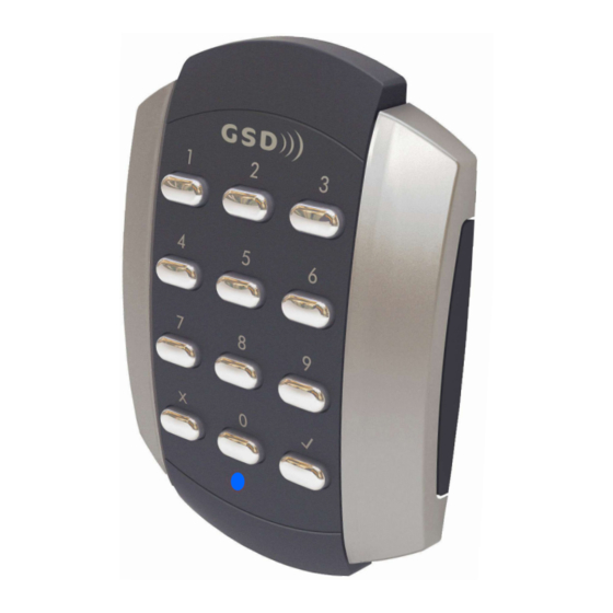
Other products from GSD
standalone products
GSD also offers fully functional standalone door controls for less complex door
management. This attractive design, with modern aesthestics, will complement
any building
- GSD Digital Keypad
- GSD Proximity Switch
- GSD Pin&Prox Switch
- GSD Biometric Switch
Features:
50 users
Access control
Door Monitoring
Manager User
Fire and Intruder alarm interface
Backlighting
Tamper resistant
5 amp relays
Indoor or outdoor use
Robust polycarbonate housing with stainless steel keys
Mounts onto a standard electrical back box
No.1 Turnpike Business Park,
Ballymount,
Dublin 22, Ireland.
Telephone: +353 1 524 2691.
Fax: +353 1 4430 430.
Contents
Initial Setup
2
Installation Diagrams
4
6
12
Enrolling Door Controls
Wi-Smart
Installation & User Manual
V1.1
Advertisement
Table of Contents

Related Manuals for GSD Digital Keypad


Summary of Contents for GSD Digital Keypad
- Page 1 Other products from GSD standalone products GSD also offers fully functional standalone door controls for less complex door management. This attractive design, with modern aesthestics, will complement any building - GSD Digital Keypad - GSD Proximity Switch - GSD Pin&Prox Switch...
- Page 2 Initial Installation The Door Control should be Factory Defaulted after installation. This will restore all default settings to the Door Control and will unenrol it from any existing GSD Controller. The Door Control will then start to scan and enrol on a GSD controller.
- Page 3 Only Note: Add a progrmming card to the Door Control. The Door Control must be disabled first if it has been enrolled onto a GSD Network Controller. Red LED Input Follow the method below to add a programming card to the Door Control.
- Page 4 Installation Diagrams Enrolling Door Controls Assigning a Door Address on Wireless Network Step Description When Surface Mounting the Door Control a Surface Mount Collar is required. - Fix Surface Mount Collar to On the Controller screen: Click ‘Wireless Network’ and then wall, ensure arrow is Click ‘Allow Doors to Join this Controller’...
- Page 5 To release Security Caps push a screwdriver into slots on the side and pull forward. Configure the required Door settings : Door Timers, Alarm Options, Door Options, Timed Actions, Inputs & Outputs. Click ‘Save’ to transmit the changes to the GSD Controller. (see 5 above)
-
Page 6: Wiring Diagrams
Wiring Diagrams Wiring Diagrams Wiring Diagram with Slave Reader Wiring Diagram with External IP3 Function 12V Linear 12V Linear Door Exit Button Door Exit Button Power supply Power supply Sounder Sounder 12V DC 12V DC Alarm/Sounder Alarm/Sounder Only Only Door Door Door Exit Door Exit... - Page 7 Wiring Diagrams Wiring Diagrams Wiring Diagram with Interlock Connection Wiring Diagram with Intruder Alarm Panel 12V Linear 12V Linear Door Exit Button Door Exit Button Power supply Power supply Sounder Sounder 12V DC 12V DC Alarm/Sounder Alarm/Sounder Only Only Door Door Door Exit Door Exit...
- Page 8 Wiring Diagrams Wiring Diagrams...
Need help?
Do you have a question about the Digital Keypad and is the answer not in the manual?
Questions and answers
Is their a battery in this unot