Advertisement
Quick Links
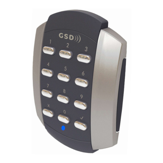
Other products from GSD
standalone products
GSD also offers fully functional standalone door controls for less complex door
management. This attractive design, with modern aesthestics, will complement
any building
- GSD Digital Keypad
- GSD Proximity Switch
- GSD Pin&Prox Switch
- GSD Biometric Switch
Features:
50 users
Access control
Door Monitoring
Manager User
Fire and Intruder alarm interface
Backlighting
Tamper resistant
5 amp relays
Indoor or outdoor use
Robust polycarbonate housing with stainless steel keys
Mounts onto a standard electrical back box
No.1 Turnpike Business Park,
Ballymount,
Dublin 22, Ireland.
Telephone: +353 1 524 2691.
Fax: +353 1 4430 430.
Contents
Initial Setup
2
Installation Diagrams
4
6
Wiring Diagrams
12
Enrolling Door Controls
Wi-Smart
Installation & User Manual
V1.0
Advertisement

Related Manuals for GSD Digital Keypad


Summary of Contents for GSD Digital Keypad
- Page 1 Other products from GSD standalone products GSD also offers fully functional standalone door controls for less complex door management. This attractive design, with modern aesthestics, will complement any building - GSD Digital Keypad - GSD Proximity Switch - GSD Pin&Prox Switch...
- Page 2 Follow the method below to add a programming card to the Door Control. The Door Control should be Factory Defaulted after installation. This will restore all default settings to the Door Control and will unenrol it from any existing GSD Controller.
- Page 3 Installation Diagrams Installation Diagrams Flush Mounting Door Control is mounted to electrical pattress box using security screws provided. Both Security Caps are then clipped onto Door Control. When Surface Mounting the Door Control a Surface Mount Collar is required. - Fix Surface Mount Collar to wall, ensure arrow is pointing upwards Surface Mounting...
- Page 4 Wiring Diagrams Wiring Diagrams Wiring Diagram with Slave Reader Wiring Diagram with Intruder Alarm Panel 12V Linear 12V Linear Door Exit Button Door Exit Button Door Contact Door Contact Power supply Power supply Sounder Sounder Door Exit Door Exit Door Door 12V DC Alarm/Sounder...
- Page 5 Wiring Diagrams Wiring Diagrams...
- Page 6 Wiring Diagrams Wiring Diagrams Wiring Diagram with External IP3 Function Wiring Diagram with Interlock Connection 12V Linear 12V Linear Door Exit Button Door Contact Door Exit Button Door Contact Power supply Power supply Sounder Sounder Door Exit Door Door Exit Door 12V DC Alarm/Sounder...
- Page 7 Configure the required Door settings : Door Timers, Alarm Options, Door Options, Timed Actions, Inputs & Outputs. Right Click on the Controller Icon & select ‘Manually Assign Addresses’ Click ‘Save’ to transmit the changes to the GSD Controller. (see 5 above) Follow Step 2 above to complete the process.
- Page 8 Wiring Diagrams Installation Notes Wiring Diagram - Smart Slave 12V Linear Power supply Buzzer Control Input 12V DC Green LED Input Only Red LED Input Tamper Alarm Output Card Present Output Data0/Data Output Data1/Clock Output Max Data Cable Length - 100m Shielded Cable Wi-Smart (See manual for detailed wiring diagram)
Need help?
Do you have a question about the Digital Keypad and is the answer not in the manual?
Questions and answers