Table of Contents
Advertisement
SPECIAL NOTICE
This product is now licensed to Anodyne Electronics Manufacturing (AEM) from Northern
Airborne Technology (NAT). AEM is responsible for all matters related to this product, including
sales, support and repair services.
Please note the transition to convert product manuals and supporting documentation is an
ongoing process and is being addressed on an 'as needed' basis.
All references to NAT product part numbers (and associated images) are equivalent to AEM
product part numbers.
Contact info:
Anodyne Electronics Manufacturing Corp.
#15-1925 Kirschner Road
Kelowna B.C. Canada
V1Y 4N7
Email:
support@aem-corp.com
Toll Free: 1-888-763-1088
Phone: 1-250-763-1088
Fax: 1-250-763-1089
www.aem-corp.com
Advertisement
Table of Contents

Related Manuals for AEM AA80 InterVOX

Summary of Contents for AEM AA80 InterVOX
- Page 1 SPECIAL NOTICE This product is now licensed to Anodyne Electronics Manufacturing (AEM) from Northern Airborne Technology (NAT). AEM is responsible for all matters related to this product, including sales, support and repair services. Please note the transition to convert product manuals and supporting documentation is an ongoing process and is being addressed on an ‘as needed’...
- Page 2 REV 5.00 April 30, 2012 Anodyne Electronics Manufacturing Corp. 15-1925 Kirschner Road Kelowna BC, Canada V1Y 4N7 Telephone (250) 763-1088 Facsimile (250) 763-1089 Website: www.aem-corp.com © 2012 Anodyne Electronics Manufacturing Corp. (AEM), All Rights Reserved CONFIDENTIAL AND PROPRIETARY TO ANODYNE ELECTRONICS MANUFACTURING CORP.
- Page 3 © 2012 Anodyne Electronics Manufacturing Corp. (AEM), All Rights Reserved This publication is the property of AEM and is protected by Canadian copyright laws. No part of this document may be reproduced or transmitted in any form or by any means including electronic, mechanical, photocopying, recording, or otherwise, without the prior written permission of AEM.
- Page 4 AA80 InterVOX Intercom Systems SM08 Installation and Operation Manual Prepared By: Checked By: Approved By: Tom Betzelt Tony Pearson Loen Clement Product Support Designer Designer Manager Apr 30, 2012 Jun 11/12 June 11, 2012 The status of this installation and operation manual is controlled by the revision shown on the title page.
-
Page 5: Table Of Contents
AA80 InterVOX Intercom Systems SM08 Installation and Operation Manual Table of Contents Section Title Page Description Introduction Purpose of Equipment Design Features Feature and Specification Summary Installation General Unpacking and Inspection 2.2.1 Warranty Installation Procedures 2.3.1 Warnings 2.3.2 Cautions 2.3.3 Notes 2.3.4... -
Page 6: Description
Section 1.0 Description Introduction The AA80 InterVOX is an advanced cockpit intercom system for general aviation flying. Built to the same exacting standards as AEM’s widely accepted AA9x/AMS series of audio controllers, the AA80 offers exceptional quality and performance at an attractive price. Since the InterVOX has more than three times... -
Page 7: Feature And Specification Summary
AA80 InterVOX Intercom Systems SM08 Installation and Operation Manual Feature and Specification Summary Input Power: 11-32 Vdc. Typical current 180mA (full o/p) 250mA maximum. May be battery operated. Headset Power: Typical 80 mW into each headset (150 Ohm David Clark Headset, or similar). - Page 8 AA80 InterVOX Intercom Systems SM08 Installation and Operation Manual AA80-060: 6 standard “carbon equivalent” microphones, 250 mVrms for full output, 600 ohm input impedance. 2 Music inputs (1K input impedance) 2.5 Vrms 1 Radio input (1K input impedance) 2.5 Vrms AA80-062: 6 standard “carbon equivalent”...
-
Page 9: Installation
Verify that all items are present before proceeding and report any shortage immediately to your supplier. 2.2.1 Warranty All Anodyne Electronics Manufacturing Corp. (AEM) products are warranted for 2 years. See the website www.aem-corp.com/warranty for complete details. Installation Procedures 2.3.1 Warnings Do not bundle any lines from this unit with transmitter coax line. -
Page 10: Notes
Allow 3 inches (8 cm) from the end of the wire to the shield termination to allow the hood to be easily installed. Note that the hoods supplied by AEM in installation kits are 'clamshell' hoods, and are installed after the wiring is completed. -
Page 11: Post Installation Checks
AA80 InterVOX Intercom Systems SM08 Installation and Operation Manual 2.3.6 Post Installation Checks Before the unit is permanently mounted, perform the following functional tests and make any needed adjustments and switch or jumper settings. Ensure that the unit is securely mounted before any flight is attempted. - Page 12 AA80 InterVOX Intercom Systems SM08 Installation and Operation Manual Unusual buzzes, hums or other background audio are symptomatic of multiple grounds, or noisy external systems such as blowers or pumps sharing wiring with the audio system. Failure to key or correctly modulate a transmitter is often caused by forgetting to connect all required grounds to the radio or external audio system.
-
Page 13: Installation Drawings
AA80 InterVOX Intercom Systems SM08 Installation and Operation Manual Installation Drawings 2.4.1 Mechanical Outline and Drilling Template April 30, 2012 Rev: 5.00 Page 2-5 ENG-FORM: 805-0100.DOTX CONFIDENTIAL AND PROPRIETARY TO ANODYNE ELECTRONICS MANUFACTURING CORP. -
Page 14: Connector Maps
AA80 InterVOX Intercom Systems SM08 Installation and Operation Manual 2.4.2 Connector Maps Note: Shown from the solder side of the mating connector. AA80-001 Version AA80-020 Version AA80-060 Version AA80-062 Version CAUTION DO NOT USE IN SAME CAUTION DO NOT USE IN SAME... -
Page 15: Adjustment Locations
AA80 InterVOX Intercom Systems SM08 Installation and Operation Manual 2.4.3 Adjustment Locations Up to serial number 2999 Serial Number 3000 and subsequent Notes: S/T adjusts level of INTERNALLY GENERATED SIDETONE (if not produced by existing radios). RX adjusts level of RECEIVE AUDIO from existing radio equipment. Should be balanced for adequate level in both InterVOX and Pilot Isolation (emergency) modes. -
Page 16: Interconnect Wiring Diagram (Vox Only -001 Version)
AA80 InterVOX Intercom Systems SM08 Installation and Operation Manual 2.4.4 Interconnect Wiring Diagram (VOX only -001 Version) April 30, 2012 Rev: 5.00 Page 2-8 ENG-FORM: 805-0100.DOTX CONFIDENTIAL AND PROPRIETARY TO ANODYNE ELECTRONICS MANUFACTURING CORP. -
Page 17: Interconnect Wiring Diagram (Ptt Ics & Vox -020 Version)
AA80 InterVOX Intercom Systems SM08 Installation and Operation Manual 2.4.5 Interconnect Wiring Diagram (PTT ICS & VOX -020 Version) April 30, 2012 Rev: 5.00 Page 2-9 ENG-FORM: 805-0100.DOTX CONFIDENTIAL AND PROPRIETARY TO ANODYNE ELECTRONICS MANUFACTURING CORP. -
Page 18: Interconnect Wiring Diagram (Vox Only -060 Version)
AA80 InterVOX Intercom Systems SM08 Installation and Operation Manual 2.4.6 Interconnect Wiring Diagram (VOX only -060 Version) April 30, 2012 Rev: 5.00 Page 2-10 ENG-FORM: 805-0100.DOTX CONFIDENTIAL AND PROPRIETARY TO ANODYNE ELECTRONICS MANUFACTURING CORP. -
Page 19: Interconnect Wiring Diagram (Ptt Ics & Vox -062 Version)
AA80 InterVOX Intercom Systems SM08 Installation and Operation Manual 2.4.7 Interconnect Wiring Diagram (PTT ICS & VOX -062 Version) April 30, 2012 Rev: 5.00 Page 2-11 ENG-FORM: 805-0100.DOTX CONFIDENTIAL AND PROPRIETARY TO ANODYNE ELECTRONICS MANUFACTURING CORP. -
Page 20: Installation Notes
AA80. This is applicable to -020 and -062 units only. 3. The ICS tie line on the -020/-062 can be connected to either another AA80 or to an AEM audio controller with ICS tie capability. This allows several possibilities for ICS expansion, depending on customer requirements. -
Page 21: System Block Diagram: Aa80-001 Version
AA80 InterVOX Intercom Systems SM08 Installation and Operation Manual 6. If a stereo music source is used with the AA80-020/-062 it can be interfaced to the single pin input (pin 12) in the following way. Note that this assumes that the low or common sides of the audio from the music source are grounded together, and are NOT BRIDGE TYPE outputs. -
Page 22: System Block Diagram: Aa80-020 Version
AA80 InterVOX Intercom Systems SM08 Installation and Operation Manual 2.5.2 System Block Diagram: AA80-020 Version April 30, 2012 Rev: 5.00 Page 2-14 ENG-FORM: 805-0100.DOTX CONFIDENTIAL AND PROPRIETARY TO ANODYNE ELECTRONICS MANUFACTURING CORP. -
Page 23: System Block Diagram: Aa80-060 Version
AA80 InterVOX Intercom Systems SM08 Installation and Operation Manual 2.5.3 System Block Diagram: AA80-060 Version April 30, 2012 Rev: 5.00 Page 2-15 ENG-FORM: 805-0100.DOTX CONFIDENTIAL AND PROPRIETARY TO ANODYNE ELECTRONICS MANUFACTURING CORP. -
Page 24: System Block Diagram: Aa80-062 Version
AA80 InterVOX Intercom Systems SM08 Installation and Operation Manual 2.5.4 System Block Diagram: AA80-062 Version End of Section 2.0 April 30, 2012 Rev: 5.00 Page 2-16 ENG-FORM: 805-0100.DOTX CONFIDENTIAL AND PROPRIETARY TO ANODYNE ELECTRONICS MANUFACTURING CORP. -
Page 25: Operation
AA80 InterVOX Intercom Systems SM08 Installation and Operation Manual Section 3.0 Operation Limitations The AA80 intercom system imposes no limitation on the original airframe. General The AA80 intercom system provides one central control for all the aircraft audio, allowing existing radio and entertainment audio to be mixed with live or voice activated intercom audio. -
Page 26: Ics Functions
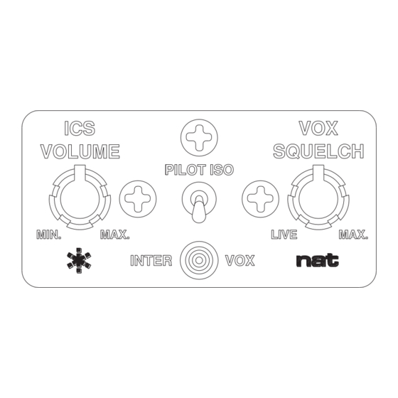
AA80 InterVOX Intercom Systems SM08 Installation and Operation Manual ICS Functions AA80-001 and AA80-060 Intercom audio may be generated in two modes between users, “LIVE” (on constantly), or “VOX” (voice activated). This is selected, along with the squelch threshold of the VOX circuit, by the “VOX SQUELCH”...
Need help?
Do you have a question about the AA80 InterVOX and is the answer not in the manual?
Questions and answers