Subscribe to Our Youtube Channel
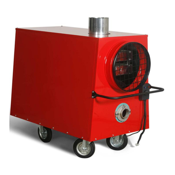
Summary of Contents for Hiton T-40
- Page 1 T-40 AND T-70 BLOWER HEATERS EQUIPPED WITH OIL BURNER Instruction and user manual 1/14 Page...
- Page 2 Fig.1 T40 construction 2/14 Page...
- Page 3 PART PART DESCRIPTION DESCRIPTION 1 Wheel_200x50 32 End cap 2 Screw cup 33 Clamp 3 Stud-bolt 34 Front cover 4 Hexagonal head screw 35 Insulating gasket 5 Hexagonal head screw 36 Combustion chamber support Round washer 37 Air outlet cover 7 Hex cap screw 38 Air outlet point 8 Hex cap screw...
- Page 4 Fig.2 T70 construction 4/14 Page...
- Page 5 PART PART DESCRIPTION DESCRIPTION Screw cup 29 Upper part A/B Cheese head screw 30 Bottom part A/B Stud-bolt 31 Bottom part A/B Hexagonal head screw 32 Smaller flue Hexagonal head screw 33 Bigger flue Round washer 34 Outlet pipe Hex cap screw 35 Support Hex cap screw 36 Exchanger support...
- Page 6 Thank you for choosing Hiton blower heater which will provide heat almost instantaneously. Low price of heating oil used for this device makes it even more economical. Our observations and experiences gained during production and sales of the blower heaters show that if exploited according to this instruction manual, the device causes no problems to their user and is almost failure-free.
- Page 7 Average fuel consumption T range heaters are portable devices. Each T-40 is equipped with a fuel tank (external tanks of any capacity may be used). T-70 heaters are not equipped with fuel tanks and can be fuelled from any plastic or metal tank meeting technical requirements.
- Page 8 Assembly T-40 heaters are fitted with oil tanks and do not require assembly. Heaters should be placed in appropriate location with respect to regulations regarding flue and chimney connection. It also applies to T-70 units. When placing them, regulations concerning connection of oil tank and storage of light heating oil should be adhered to.
- Page 9 min cycles after the burner has been switched off. The blue button should be switched on if you want to ventilate the device - the red button should be switched off during this time. Set the thermostat at a desired value. Press the red button (the fan and burner will switch on simultaneously).
- Page 10 Fuel mixed with water looks like water with sugar on the filter; working even for a few hours under such circumstances may cause damage to the fuel pump. Heater should operate in building/s with efficient air ventilation with the inside temperature not lower than +5 ...
- Page 11 temperature where it is located. Tanks should have minimum 32 mm diameter vent holes. Mark the tank and place appropriate fire extinguisher next to it. Possible remedies Burner will not start Damaged safety device of the network or the burner. ...
- Page 12 Water in fuel. Air-locked fuel line. No supply. There is a flame but keeps on extinguishing Leaking electromagnetic valve. Damaged contacts of the control panel. Improper angle of fuel nozzle injection. Improper fitting of the disk. ...
- Page 13 Set the heater knob at the maximum value. Set the external thermostat to desired temperature. NOTE: for thermostats powered by 220 V transmitters should be mounted. NOTE Failure to comply with the above instruction manual may cause damage to the heater, which will result in the warranty to become void.
- Page 14 14/14 Page...


Need help?
Do you have a question about the T-40 and is the answer not in the manual?
Questions and answers