Table of Contents
Advertisement
Advertisement
Table of Contents

Related Manuals for Hiton HP-115


Summary of Contents for Hiton HP-115
- Page 1 USER MANUAL UNIVERSAL OIL HEATER HP-115 AND HP-125...
- Page 2 • appropriate ventilation of heated area 4. Characteristics of the control panel: the heater may be regulated and set at 15 and 22kW (HP-115) or 22 and 30 kW (HP-125), protection against overheating the burner, protection against overflow of oil in the burner, automatic retaining of previous settings in case of power failure, 5.
- Page 3 6. Burner’s construction Figure 1: Diagram of HP-115 and HP-125 universal oil heater Symbols: Bimetallic sensor of burner’s temperature T100 Bimetallic thermostat (STB) Overflow fuse Pump (48W [230V AC, 50Hz]) Fan (35W [230V/50Hz], capacity 600 m³/h (HP-115), capacity l000 m³/h (HP-125)
- Page 4 Keyboard Heater overheating indicator Overflow tank indicator Pump engine rotational speed indicator Heater turn on/off indicator Figure 2. Control panel 7. Installation When installing the heater, all local regulations are to be complied with, including regulations referring to national and European norms. Place the heater on flat surface made of concrete.
- Page 5 Ventilation fans working in the same room or area as the heater may cause disruptions. Fitting the flue To ensure the right combustion appropriate fitting of the flue in necessary. The following recommendations should be adhered to when fitting the flue: Minimum flue diameter - 150mm.
- Page 6 Figure 3. Fitting the flue 8. Description of use Control panel The control panel of HP-115and HP-125 universal oil heater is equipped with four buttons enabling the user to control the operation of the heater and four diodes signalling the operating modes of the device.
- Page 7 During this time, the pump feeds the combustion chamber with approximately 1.25 kg/h (HP-115) or 1.85 kg/h (HP-125) of oil. After 30 minutes, we may shift to second gear (on the screen displayed as “+” – yellow diode is bright), during which time the chamber is supplied with approximately 1.85 kg/h (H-P115) or 2.55 kg/h (HP-125) of oil.
- Page 8 on the control panel switches on. Ventilation fan works until the temperature in the chamber falls below 35°C. After the temperature in the chamber has fallen below 35°C, the burner switches to the Stop mode Once the heater is in the Stop mode (and even after switching off and subsequently switching on the device) the overheating signal is on.
- Page 9 15 kW; 1.25 kg/h – HP-115 and 22 kW; 1.85 kg/h – HP-125 The second gear, with increased performance can be activated (“+” on the screen) after 30 minutes following the activation of the heater: 22kW;...
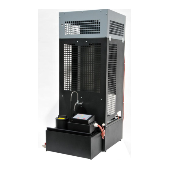
- Page 10 Figure 6. Heater construction- 1. Burner basin 2. Ring 3. Combustion chamber 4. Cylinder 5. Fuel tank 6. Pump and control panel 7. Oil feed line 8. Combustion chamber lid...
- Page 11 Maintenance The burner requires various maintenance works. Following producer’s recommendations regarding maintenance will assure failure-free and safe functioning of the device. Vaporising pan and elements of the combustion chamber (cylinder, ring and lid) should be cleaned daily. Check if the oil overflow pipe is unobstructed (this pipe is located in the lower part of the combustion chamber, directly above the overflow tank), and clean if necessary.
- Page 12 10. Failures In case of a failure of the device, the following list may help identify its cause and remedy. Generally, it should be easy to fix. The following are the most common problems. Digits represent possible causes. The order of digits suggests gradation of probable cause of the failure. CAUTION! Unplug the device before starting to fix the problem.
- Page 13 Extend the flue Insulate the flue on the outside of the building Read information about the flue in this guide. TECHNICAL SPECIFICATIONS: HP115 HP125 Minimum heating performance Maximum heating performance Minimum oil consumption kg/h 1,25 1,85 Maximum oil consumption kg/h 1,85 2,55...
- Page 14 ABIZA 05-825 Grodzisk Mazowiecki Opypy, ul.Jemiołowa 2 EN 1 Type: HP 115 Distance from combustible materials: 140 cm Class: 5 Heating performance: 22 kW Fuel type: Diesel oil Electric security: complied with ABIZA 05-825 Grodzisk Mazowiecki Opypy, ul. Jemiołowa 2 EN 1 Type: HP 125 Distance from combustible materials: 140 cm...
- Page 15 Adres: Address: Produkt: Marka: HP Product: Model: HP-115 Niniejszym deklarujemy z całą odpowiedzialnością, że wymienione produkty spełniają wymagania bezpieczeństwa Dyrektyw Europejskich. We herby declare In sole responsibility that the designated product fulfills the safety requirements of the European Directives. Dyrektywy: 2006/95/WE Dyrektywą...
- Page 16 DEKLARACJA ZGODNOŚCI WE EC DECLARATION OF CONFORMITY Producent: ABIZA Manufacturer 05-825 Grodzisk Mazowiecki Opypy, ul.Jemiołowa 2 Adres: Address: Produkt: Marka: HP Product: Model: HP-125 Niniejszym deklarujemy z całą odpowiedzialnością, że wymienione produkty spełniają wymagania bezpieczeństwa Dyrektyw Europejskich. We herby declare In sole responsibility that the designated product fulfills the safety requirements of the European Directives.
Need help?
Do you have a question about the HP-115 and is the answer not in the manual?
Questions and answers
oljepump till interloop hp 125
The oil pump HP-105-145R is compatible with the Hiton HP-115 used oil stove.
This answer is automatically generated