Panasonic WV-CF374E Installation Manual
Color cctv camera
Hide thumbs
Also See for WV-CF374E:
- Operating instructions manual (28 pages) ,
- Operating instructions manual (27 pages)
Table of Contents
Advertisement
Quick Links
Installation Guide
Color CCTV Camera
WV-CF374E
Model No:
WV-CF354E
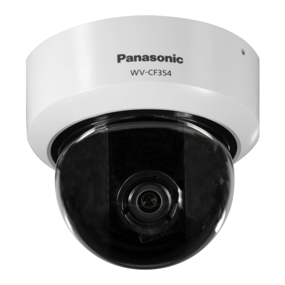
WV-CF344E
This illustration represents WV-CF344E.
Before attempting to connect or operate this product,
please read these instructions carefully and save this manual for future use.
The model number is abbreviated in some descriptions in this manual.
Advertisement
Table of Contents


Need help?
Do you have a question about the WV-CF374E and is the answer not in the manual?
Questions and answers