
Related Manuals for QSC PS‑1600H


Summary of Contents for QSC PS‑1600H
- Page 1 ™ Hardware User Manual PS‑1600(H/G) – Sixteen-Button Page Station PS‑1650(H/G) – Sixteen Command-Button Page Station PS‑800(H/G) – Eight Command-Button Page Station PS‑400(H/G) – Four Command-Button Page Station TD-000324-01-B *TD-000324-01*...
-
Page 2: Important Safety Instructions
EXPLANATION OF TERMS AND SYMBOLS The term “WARNING!” indicates instructions regarding personal safety. If the instructions are not followed the result may be bodily injury or death. The term “CAUTION!” indicates instructions regarding possible damage to physical equipment. If these instructions are not followed, it may result in damage to the equipment that may not be covered under the warranty. -
Page 3: Fcc Statement
FCC Statement NOTE!: This equipment has been tested and found to comply with the limits for a Class B digital device, pursuant to Part 15 of the FCC Rules. These limits are designed to provide reasonable protection against harmful interference in a residential installation. This equipment generates, uses and can radiate radio frequency energy and, if not installed and used in accordance with the instructions, may cause harmful interference to radio communications. -
Page 4: Package Contents
Package Contents H Model N Model Part Part 1. Q-Sys Page Station H Model 1. Q-Sys Page Station G Model 2. Hardware User Manual 3. Page Station Quick Start Guide 4. Connector ship kit 5. Connector ship kit a. 6-pin Euro plug b. - Page 5 Introduction Q-Sys is a platform of software and hardware products providing system designers and operators with the tools necessary to design, configure, and manage medium to large scale audio systems. In addition to the primary signal processing and system management components that make up a Q-Sys audio system, the Q-Sys solution includes peripheral components that offer services such as remote management and paging.
-
Page 6: Inputs And Outputs
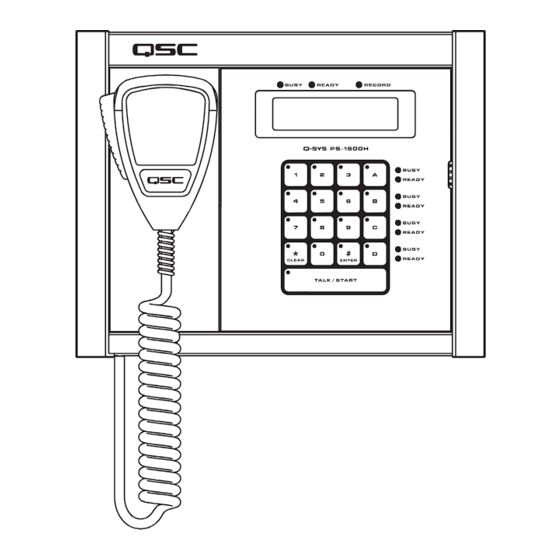
If service is required and the original packing material is not available, ensure that the unit is adequately protected for shipment (use a strong box of appropriate size, sufficient packing/padding material to prevent load shifting or impact damage) or call QSC’s Technical Services Group for replacement packing material and a carton. - Page 7 Features Q‑Sys PS‑1600H and N Front Panel Figure 2. To see the keypad configurations of Page Station models PS-1650, PS-800, and PS-400 , see page 16. Refer to — Figure 2 — 1. LED touch indicators 6. Global Busy, Ready and Record Indicators 2.
- Page 8 LED Touch Indicators When a key is pressed, the LED on that key illuminates to indicate that it was pressed. Capacitive Touch Keypad • Command buttons can be assigned one of several different types of Commands using the Q-Sys Designer Administration Interface. Once assigned, you just have to press the appropriate Command button to initiate the action.
- Page 9 Magnetic Microphone Docking Plate The Q-Sys Page Station uses a magnetic docking plate to hold the hand-held microphone. Just place the back of the microphone up against the plate and let it go! Available with hand-held microphone models only. Q‑Sys Page Station Rear Panel Refer to Figure Gooseneck version...
-
Page 10: Microphone Connector
Microphone Connector • RJ45 connector for hand-held microphone models. • The gooseneck microphone is not user-replaceable. Please contact QSC Support for details if it needs repair. Strain relief Secures the cord of the hand-held microphones to remove any stress to the RJ45 connector. -
Page 11: Optional Connections
NPIO Connector (Figure 10, and Figure 11) The Page Station rear panel includes a six-terminal receptacle that provides various GPIO (General Purpose Inputs and Outputs) that allows the Page Station to control or be controlled by a variety of external products. The Page Station GPIO receptacle accepts Euro style (Phoenix) two, three or six-terminal plugs. -
Page 12: Required Connections
• LAN B — IP Addr 169.254.55.4 — Netmask 255.255.0.0 • Firmware Version — 2.0.111 • Copyright (C) 2010 — QSC Audio Products, LLC. Reset the Page Station to Factory Defaults 1. If the Page Station is part of a running design, do the following: a. - Page 13 Mounting the Hand‑held Microphone Models NOTE!: The product shall be installed in accordance with the applicable code requirements. The tripple-gang electrical box must be UL listed, and the dimensions must meet NEMA standards. Q-Sys Page Stations are designed to be mounted on a wall or podium with an appropriate cutout and cavity to allow all cables and power sources to connect to the Page Station rear panel with adequate stress relief.
- Page 14 Mounting the Nooseneck Microphone Models There are two methods of mounting the Gooseneck Microphone Page Stations. You can mount the Page Station onto the mounting surface with the Page Station at a 30° angle to the mounting surface or into a podium or other surface so that the Page Station surface is flush with the mounting surface.
-
Page 15: Specifications
Specifications Hardware Dimensions (H/W/D) 10.37” x 8.3” x 1.5” (263.4 mm x 210.8 mm x 38.1 mm) Line voltage requirements IEEE 802.3af power or +24 VDC/500 mA Accessories included Hardware User Manual, Accessory ship kit, Warranty card Audio Channel Capacity Line Inputs Line Outputs Front Panel Controls... -
Page 16: Keypad Configurations
Keypad Configurations The following keypads are available with both the hand-held, and gooseneck models. — Figure 22 — — Figure 23 — — Figure 24 — — Figure 25 —... - Page 17 Designed and assembled in the USA © 2011 - 2012, QSC Audio Products, LLC. QSC Audio Products, LLC. All rights reserved. QSC and the QSC logo are registered trademarks of QSC Audio Products, LLC in the U.S. Patent and Trademark office and other countries. Q-Sys, Q-LAN, Q-Sys Core Processor, Q-Sys Core 1000, Q-Sys Core 3000, Q-Sys Core 4000, Q-Sys I/O Frame, and Q-Sys Designer are trademarks of QSC Audio Products, LLC.
Need help?
Do you have a question about the PS‑1600H and is the answer not in the manual?
Questions and answers