Table of Contents
Advertisement
Quick Links
WARNING
Improper
adjustment, alteration, service or
maintenance can cause injury or
property
damage.
instruction manual thoroughly
before installing or servicing this
equipment.
WARNING
1. Do not store or use gasoline or
other
flammable
liquids in the vicinity of this or
any other appliance.
2. An LP tank not connected for
use should not be stored in the
vicinity of this or any other
appliance.
DANGER
If you smell gas:
1. Shut off gas to the appliance.
2. Extinguish any open flames.
3. Open the oven door.
4. If the odor continues, keep
away from the appliance and
immediately
call
supplier or fire department.
WARNING
For Outdoor Use Only
ATTACH YOUR RECEIPT HERE
Serial Number____________________ Purchase Date____________________
installation,
Read
this
vapors
and
your
gas
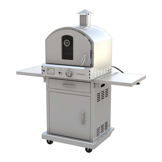
Outdoor Pizza Oven
1
MODEL # PL8430SSBG070
Advertisement
Table of Contents

Related Manuals for Pacific Living PL8430SSBG070


Summary of Contents for Pacific Living PL8430SSBG070
- Page 1 Outdoor Pizza Oven MODEL # PL8430SSBG070 WARNING Improper installation, adjustment, alteration, service or maintenance can cause injury or property damage. Read this instruction manual thoroughly before installing or servicing this equipment. WARNING 1. Do not store or use gasoline or...
-
Page 2: Oven Operation
Questions, problems, missing parts? Before returning to your retailer, call our customer service department at 1-866-410-0408, Monday - Friday, 8 a.m. - 5 p.m., PST. Oven Operation 1-2-3 Before Cooking: Step 1 Keep your oven a safe distance away from your property.* Step 2 Always perform a leak test.* Step 3... -
Page 3: Table Of Contents
TABLE OF CONTENTS Safety Information…………………………………….………...….………….………….…. ………4 Package Contents…..………………..…..….……...…....………………………………..6 Hardware Contents……………………………………………………………….……………………7 Preparation…..………………..…………………..….……………………………………………..….8 Assembly Instructions……………………..……………….………………………………………...9 Natural Gas Conversion……………………………………………..........17 Operation Instruction…………………………….……...……………………………....23 Care and Maintenance……………………………….………………………………………………32 Troubleshooting …………………………………………………………………..….……………...42 Warranty………………………………………………………………………………………………..44 Explored Diagram……………….……………………………………………………………….…..45 Replacement Parts List…….………………………………………………………………………..47... -
Page 4: Safety Information
SAFETY INFORMATION Please read and understand this entire manual before attempting to assemble, operate or install the product. If you have any questions regarding the product, please call customer service at 1-866-410-0408 Monday to Friday from 8 a.m. to 5 p.m. PST. 1. - Page 5 SAFETY INFORMATION 16. The cylinder used must include a collar to protect the cylinder valve. 17. Do not store a spare LP-gas cylinder under or near this appliance. 18. Never fill the cylinder beyond 80 percent full. 19. If the information in “17” and “18” is not followed exactly, a fire causing death or serious injury may occur.
-
Page 6: Package Contents
PACKAGE CONTENTS PART DESCRIPTION QUANTITY PART DESCRIPTION QUANTITY Main Body Bottom Grill Cooking Grill Fat Cup Pizza Stone Smoker Box Flame Tamer... - Page 7 NATURAL GAS CONVERSION The following list is included inside the pizza oven carton: Battery 1 pc The following list is not included inside the pizza oven carton, but needed when the user is assembling the pizza oven. Phillips Head Screwdriver 1 pc The following list is not included inside the pizza oven carton but is included inside the NG conversion kit.
-
Page 8: Preparation
NATURAL GAS CONVERSION PREPARATION Before beginning assembly of product, make sure all parts are present. Compare parts with package contents list and hardware contents list. If any part is missing or damaged, do not attempt to assemble the product. Assembly tip! (Please lightly tighten the screws during assembly of the cart. When the cart is completed THEN TIGHTEN ALL THE screws. - Page 9 NATURAL GAS CONVERSION 3. Use screw M6*12×2 pcs to fix the left side panel onto the base panel of the stand. (Note: The panel should have the “small holes at the top” to the front of the cart assembly) 4. Use screw M6*12×2 pcs to fix the right side panel onto the base panel of the stand.
- Page 10 NATURAL GAS CONVERSION 6. Use screw M6*12×5 pcs to attach the stand base panel onto the base panel, between the two side panels. 7. Use screw M4*10×4 pcs to fix the stand door horizontal beam between the two side panels. (Note: Please fasten the upper two screws first, and then the lower two screws.)
- Page 11 NATURAL GAS CONVERSION 9. Use screw M5*10×8 pcs to attach triangle×2 pcs on the bottom of the base panel, leaning against the two side panels. (Note: it is CRITICAL that you only insert the screws with a few turns until all are in BEFORE you tighten them) 10.
- Page 12 NATURAL GAS CONVERSION 12. Put the oven assembly on the stand-top panel. Use screw M6*12×4 pcs to fasten the oven onto the stand. (Note: These screws can be tightened at this time) 13. Use screw M5*10×16 pcs to attach side shelf bracket×4 pcs onto the drawer side panels.
- Page 13 NATURAL GAS CONVERSION 14. Use screw M6*12×8 pcs and special nut TB31-05-03×8 pcs to hang side shelf×2 pcs onto the four brackets. (Note: These screws can be tightened at this time) 15. Use screw M4*8×3 pcs to fix the chimney assembly onto the top of the oven exterior.
- Page 14 NATURAL GAS CONVERSION 16. Use screw M5*35×4 pcs to fix the back heat shield onto the back panel of the oven. The order is: screw→back heat shield→heat insulation washer→flat washer→ oven back panel. 17. Put the following accessories into the oven and close the oven door: - base grill×1 pc - pizza stone×1 pc...
- Page 15 NATURAL GAS CONVERSION PREPARATION: Before beginning conversion, make sure all parts are present. Compare parts with package contents. If any part is missing or damaged, do not attempt to convert. Contact customer service for replacement parts. 1. Turn off gas supply, and then remove cap on gas supply side. 2.
- Page 16 NATURAL GAS CONVERSION IMPORTANT: After your outdoor kitchen is converted to natural gas, the working pressure for natural gas is 7-inche water column (WC). Gas pressure is affected by gas line size and the length of gas line run from house. Follow the recommendations in the chart below. From House to Grill Distance Tubing Size...
- Page 17 NATURAL GAS CONVERSION 20. Loosen the screws that are used to fasten the burner (see picture at right). Use a 10x12 mm spanner to remove the thermocouple out from the burner. Next, pull out the ignition wire from the electronic igniter. Finally, take out the whole burner.
- Page 18 NATURAL GAS CONVERSION 23. Put the burner back into the oven and insert the ignition wire into the original position. Use the 10x12 mm spanner to fix the thermocouple back into the oven again. Finally, fasten the burner with the original screws. 24.
- Page 19 NATURAL GAS CONVERSION 26. Use the screw driver to put the conversion screw into the knob. 27. When converting to natural gas, please be aware that the low heat setting of the main burners and searing burner is “NG LOW,” as shown on the control panel.
-
Page 20: Natural Gas Conversion
NATURAL GAS CONVERSION Burner LP Gas Natural Gas Main Burner 16,000 BTU / Hr 16,000 BTU / Hr CAUTION: If low flames or burner problems are observed after converting from LPG to NG, the natural gas lines may not be large enough. Refer to the “From House to Grill” chart below natural gas supply line specifications. -
Page 21: Care And Maintenance
CARE AND MAINTENANCE Never attach an unregulated gas line to the appliance. Connection to an unregulated gas line can cause excessive heat or fire. Verify the type of gas supply to be used, either Natural Gas (N.G.) or Liquid Propane (L.P.), and make sure the serial plate agrees with that of the supply. - Page 22 CARE AND MAINTENANCE L.P. GAS INSTALLATION Gas grills that are set to operate with L.P. gas come with a high capacity hose and regulator assembly. (Note: Only use the pressure regulator and hose assembly supplied with the grill or a replacement pressure regulator and hose assembly specified by the manufacturer).
- Page 23 CARE AND MAINTENANCE Fig. 6 DO NOT use a wrench to tighten because it could damage the quick coupling nut and result in a hazardous condition. 7. Open the tank valve fully (counterclockwise). Use a soapy water solution to check all connections for leaks before attempting to light your grill.
- Page 24 CARE AND MAINTENANCE Thermally Propane Sensitive Nut Regulator External Hand Wheel Thread Type I Valve PIG 7 Disconnecting a Liquid Propane Gas (LP Gas) Tank from Your Grill: 1. Turn the burner knobs and LP gas tank valve to the full OFF position. (Turn clockwise to close.) 2.
- Page 25 CARE AND MAINTENANCE valve outlet and inlet connection ANSI/CGA-V-1. Cylinders must not be stored in a building, garage, or any other enclosed area. (The L.P. cylinder must have an overfill protection device and a collar to protect the cylinder valve.) The L.P.
- Page 26 CARE AND MAINTENANCE 5. Turn off the burner control knobs. 6. Turn the top knob of the fuel supply cylinder counterclockwise two (2) rotations to open. 7. Apply the soap solution to connections of the fuel supply assembly. If no soap bubbles appear, there is no gas leak.
- Page 27 CARE AND MAINTENANCE Clearance to combustible construction: A minimum of 61 cm (24 inches) from the sides and back must be maintained from the gas grill above and below the cooking surface to adjacent vertical combustible construction. Clearance to non-combustible construction: A minimum of 61 cm (24 inches) clearance from the back of the grill to non-combustible construction is required for the lid to fully open.
- Page 28 CARE AND MAINTENANCE heat or smoke away from the heat and smoke exhaust holes. GENERAL RULES Do not leave the grill unattended while cooking! 1. Make sure the grill has been leak-tested and is properly located. 2. Light the grill burners using the instructions provided in this manual. 3.
- Page 29 CARE AND MAINTENANCE GRILL BURNER LIGHTING Warning: Do not lean over grill when lighting. Turn off LP supply at cylinder when appliance is not in use. Main Burner Lighting Illustration: 1. Check that the control knobs are in the OFF position.
-
Page 30: Operation Instruction
CARE AND MAINTENANCE USING THE GRILL LIGHT Light Operation Instruction 1. Make sure the light’s power switch on the control panel is in the “OFF” position. 2. Connect power plug to properly grounded outlet. 3. Turn the light’s power switch to “ON.” WARNING Keep any electrical supply cord away from any heated surface. - Page 31 CARE AND MAINTENANCE Normal:Soft blue flames Out of Acjustment:Hard blue flames-too much air Poor Combustion:wavy,yellow flames-too little air GENERAL CLEANING IMPORTANT: Before cleaning, make sure all controls are off and the grill is cool. Always follow label instructions on cleaning products. For routine cleaning, wash with soap and water using a soft cloth or sponge.
- Page 32 CARE AND MAINTENANCE NOTE: Allow the drip tray to cool before attempting to clean. Important: Do not leave the grill outside during inclement weather unless it is covered. Rain water can collect inside of the grill, the grill cart or the drip tray if left uncovered. If the drip tray is not cleaned after use and the grill is left uncovered, the drip tray will fill with water causing grease and water to spill into the grill cart.
- Page 33 CARE AND MAINTENANCE NOTE: Always scrub in the direction of the grain. GRILL LIGHT Bulb Replacement IMPORTANT SAFETY INSTRUCTIONS Lighted lamp is HOT: WARNING -TO REDUCE THE RISK OF FIRE, ELECTRIC SHOCK, EXPOSURE TO EXCESSIVE UV RADIATION, OR INJURY TO PERSONS. 1.
- Page 34 CARE AND MAINTENANCE 28. Turn off/unplug and allow to cool before replacing bulb (lamp). Next, open the door and remove the two cooking grills, smoker box, pizza stone, base grill and flame tamer. 29. Use screw driver to loosen M5*35 screw * 4 pcs that fix the heat shield.
- Page 35 CARE AND MAINTENANCE 31. Use one hand to hold the metal back part of the light and one handle to hold the front glass cover and then take them apart. Then you can replace the bulb. 32. After replacement, use one hand to hold the metal back part of the light and one handle to hold the front glass cover and then clip...
- Page 36 CARE AND MAINTENANCE 33. Use M4*10 screw to fix the light assy. on to the back panel of the oven. 34. Use screw M5*35×4 pcs to fix the back heat shield onto the back panel of the oven. The order is: screw→back heat shield→heat insulation washer→flat washer→...
- Page 37 CARE AND MAINTENANCE Cleaning Method Follow Steps 28 to 31 above for glass cover removal. Use a damp towel to clean the surface of glass cover. Make sure the glass cover is completely dry before reinstalling. WARNING Make sure the light switch is on “OFF” position and power plug is disconnected from power outlet prior to cleaning the glass cover.
- Page 38 CARE AND MAINTENANCE 5. Do not use an outdoor cooking gas appliance for purposes other than intended. 6. When connecting, first connect plug to the outdoor cooking gas appliance then plug appliance into the outlet. 7. Use only a Ground Fault Interrupter (GFI) protected circuit with this outdoor cooking gas appliance.
- Page 39 CARE AND MAINTENANCE 38. Use spanner 19# to loosen the nut that fix the temp. gauge. And then you can completely separate the oven door exterior and interior so as to do the cleaning. 39. After cleaning, you need to re-assemble the oven door.
- Page 40 CARE AND MAINTENANCE 41. Use M4*10 screw * 4 pcs to fix the door onto the oven. Now you have finished cleaning the oven door.
-
Page 41: Troubleshooting
TROUBLESHOOTINGE Many solutions given here can make your grilling experience safer and more enjoyable. You can also call the customer service department at 1-866-410-0408, 8 a.m. – 5 p.m., PST, Monday to Friday. PROBLEM POSSIBLE CAUSE CORRECTIVE ACTION Grill will not 1. - Page 42 TROUBLESHOOTINGE Burner Orifice Size Φ1.8 mm Main Burner 2. Clear ports of any obstructions. 3. Refill the LP tank. Low heat, LP The propane regulator assembly Please follow these instructions: 1. Make sure all burners are “OFF.” gas. incorporates an excess flow device designed to supply the grill with 2.
-
Page 43: Warranty
WARRANTY Proof of purchase is required to access this warranty program, which is in effect from the date of purchase. Customers will be subject to parts, shipping, and handling fees if unable to provide proof of the purchase or after the warranty has expired. If you have any questions or problems, call customer service department at 1-866-410-0408, 8 a.m. - Page 44 Exploded Diagram For replacement parts, call our customer service department at 1-866-410-0408, 8 a.m. – 5 p.m., PST, Monday to Friday.
-
Page 45: Explored Diagram
Exploded Diagram Part Name Part Name Heat spacer Grease tray left bracket Back heat-shield Oven back support Light assy. Grease tray right bracket Light bracket Oven right supporting assy. Handle latch Light transformer Gas pipe Match holder Chimney assy. Camp stove superior girder Cooking grill Right side shelf bracket Smoker box assy. -
Page 46: Replacement Parts List
Replacement Parts List 1 、 BG070-01 2. BG070-02-00B Oven BG070-24 Burner 4. BG070B-03-01 Oven Oven Interior * 1 pc Bracket Beam * 1 pc Back Panel * 1 pc Exterior * 1 pc BG070-03A Oven 6. BG070-10-00B Burner BG070-18 Cooking BG070-17B Base Back Heat Shield * 1 pc... - Page 47 Replacement Parts List BG070B-38 Oven BG070-30 Temp. 27. BG070-12-00 Oven BG070-76-00 Door Glass * 2 pc Gauge * 1 pc Door Handle Assy. * 1 pc Sideshelf * 2 pcs 29. BG070B-30-01 Left 30. BG070B-30-02 Right 31. BG070B-57-00 Oven 32. BG070B-58-00 Oven Sideshelf Bracket * 2 Sideshelf Bracket * 2 Left Holder Panel * 1 pc...
- Page 48 Replacement Parts List 49. BG070B-53 Trolley 50. BG070B-54 Trolley BG070B-50-00 BG070B-51-00 Top Panel * 1 pc Door Horizontal Beam * Trolley Left Sidepanel Trolley Right Sidepanel 1 pc Assy. * 1 pc Assy. * 1 pc 53. BG070B-52 Trolley 54. BG070B-55 Trolley 55.
Need help?
Do you have a question about the PL8430SSBG070 and is the answer not in the manual?
Questions and answers