Table of Contents
Advertisement
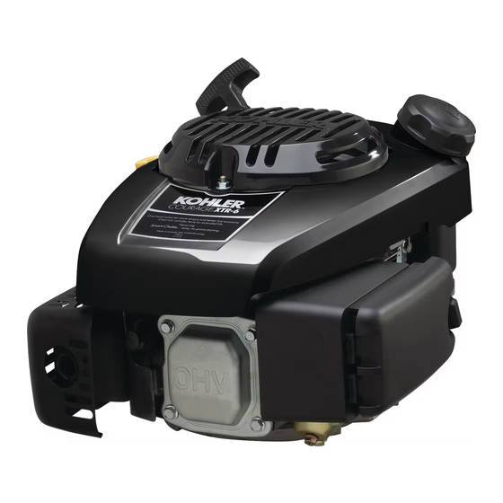
XT-6, XTR-6, XT6.5, XT650, XT6.75, XT675,
XT-7, XTR-7, XT775, XT8
Service Manual
IMPORTANT:
Read all safety precautions and instructions carefully before operating equipment. Refer to operating
instruction of equipment that this engine powers.
Ensure engine is stopped and level before performing any maintenance or service.
2
Safety
3
Maintenance
5
Specifications
10
13
Troubleshooting
17
18
Fuel System
24
26
27
31
33
45
14 690 01 Rev. G
KohlerEngines.com
1
Advertisement
Table of Contents
Troubleshooting

Related Manuals for Kohler XT-6


Summary of Contents for Kohler XT-6
- Page 1 XT-6, XTR-6, XT6.5, XT650, XT6.75, XT675, XT-7, XTR-7, XT775, XT8 Service Manual IMPORTANT: Read all safety precautions and instructions carefully before operating equipment. Refer to operating instruction of equipment that this engine powers. Ensure engine is stopped and level before performing any maintenance or service.
- Page 2 Safety SAFETY PRECAUTIONS WARNING: A hazard that could result in death, serious injury, or substantial property damage. CAUTION: A hazard that could result in minor personal injury or property damage. NOTE: is used to notify people of important installation, operation, or maintenance information. CAUTION WARNING WARNING...
- Page 3 Have a Kohler authorized dealer perform this service. REPAIRS/SERVICE PARTS Kohler genuine service parts can be purchased from Kohler authorized dealers. To find a local Kohler authorized dealer visit KohlerEngines.com or call 1-800-544-2444 (U.S. and Canada). 14 690 01 Rev. G...
- Page 4 OIL RECOMMENDATIONS STORAGE If engine will be out of service for 2 months or more We recommend use of Kohler oils for best performance. follow procedure below. Other high-quality detergent oils (including synthetic) of API (American Petroleum Institute) service class SJ 1.
-
Page 5: Specifications
Kohler engine identification numbers (model, specification and serial) should be referenced for efficient repair, ordering correct parts, and engine replacement. Model ..... XT-6 Courage Engine... - Page 6 Specifications TORQUE SPECIFICATIONS XT-6, XTR-6 XT6.5, XT650, XT-7, XTR-7, XT6.75, XT675 XT775, XT8 Connecting Rod Cap Fastener (torque in increments) 12.5 N·m (110 in. lb.) Crankcase Oil Drain Plug 13.6 N·m (120 in. lb.) Oil Pan Screw 11.0 N·m (98 in. lb.) 14.7 N·m (130 in.
- Page 7 Specifications CLEARANCE SPECIFICATIONS XT-6, XTR-6 XT6.5, XT650, XT-7, XTR-7, XT6.75, XT675 XT775, XT8 Camshaft End Play 0.3/0.85 mm (0.0118/0.0335 in.) Running Clearance 0.013/0.0555 mm (0.00051/0.00217 in.) Connecting Rod Connecting Rod-to-Crankpin Running Clearance 0.025/0.045 mm (0.0009/0.0017 in.) Connecting Rod-to-Crankpin Side Clearance 0.03/0.48 mm...
- Page 8 Specifications CLEARANCE SPECIFICATIONS XT-6, XTR-6 XT6.5, XT650, XT-7, XTR-7, XT6.75, XT675 XT775, XT8 Governor Governor Cross Shaft -to-Crankcase Running Clearance 0.020/0.064 mm (0.0007/0.0025 in.) Cross Shaft O.D. 5.96/5.98 mm (0.2346/0.2354 in.) Gear Shaft O.D. 6.01/6.03 mm (0.2366/0.2374 in.) Governor Gear Shaft-to-Governor Gear Running Clearance 0.09/0.19 mm (0.0035/0.0074 in.)
- Page 9 Specifications GENERAL TORQUE VALUES English Fastener Torque Recommendations for Standard Applications Bolts, Screws, Nuts and Fasteners Assembled Into Cast Iron or Steel Grade 2 or 5 Fasteners Into Aluminum Size Grade 2 Grade 5 Grade 8 Tightening Torque: N·m (in. lb.) ± 20% 8-32 2.3 (20) 2.8 (25)
- Page 10 For checking combustion retention and if cylinder, piston, rings, or valves are worn. Individual component available: Design Technology Inc. Adapter 12 mm x 14 mm (Required for leakdown test on XT-6 engines) DTI-731-03 Dealer Tool Kit (Domestic) Kohler 25 761 39-S Complete kit of Kohler required tools.
- Page 11 For reaming worn valve guides to accept replacement oversize valves. Can be used in low-speed drill press or with handle below for hand reaming. Reamer Handle Design Technology Inc. For hand reaming using Kohler 25 455 12-S reamer. DTI-K830 AIDS Description Source/Part No.
- Page 12 Tools and Aids FLYWHEEL HOLDING TOOL ROCKER ARM/CRANKSHAFT TOOL A flywheel holding tool can be made out of an old junk A spanner wrench to lift rocker arms or turn crankshaft flywheel ring gear and used in place of a strap wrench. may be made out of an old junk connecting rod.
-
Page 13: Troubleshooting
Troubleshooting TROUBLESHOOTING GUIDE When troubles occur, be sure to check simple causes which, at first, may seem too obvious to be considered. For example, a starting problem could be caused by an empty fuel tank. Some general common causes of engine troubles are listed below and vary by engine specification. Use these to locate causing factors. - Page 14 Troubleshooting EXTERNAL ENGINE INSPECTION Engine Loses Power NOTE: It is good practice to drain oil at a location away ● Dirty air cleaner element. from workbench. Be sure to allow ample time for ● Engine overheated. complete drainage. ● Excessive engine load. ●...
- Page 15 Troubleshooting CRANKCASE VACUUM TEST WARNING WARNING Carbon Monoxide can cause severe nausea, Rotating Parts can cause severe injury. fainting or death. Stay away while engine is in operation. Avoid inhaling exhaust fumes. Engine exhaust gases contain poisonous carbon Keep hands, feet, hair, and clothing away from all monoxide.
- Page 16 Troubleshooting COMPRESSION TEST For Command Twins: A compression test is best performed on a warm engine. Clean any dirt or debris away from base of spark plug(s) before removing them. Be sure choke is off, and throttle is wide open during test. Compression should be at least 160 psi and should not vary more than 15% between cylinders.
-
Page 17: Air Cleaner/Intake
Air Cleaner/Intake AIR CLEANER Precleaner (if equipped) These systems are CARB/EPA certified and components 1. Remove precleaner. should not be altered or modified in any way. 2. Replace or wash precleaner in warm water with Air Cleaner Components detergent. Rinse and allow to air dry. 3. -
Page 18: Fuel System
FUEL LINE ● Fuel line. Low permeation fuel line must be installed on carbureted ● In-line fuel filter. Kohler Co. engines to maintain EPA and CARB ● Fuel tank filter (in-nipple). regulatory compliance. ● Fuel shut-off valve (if equipped). ● Carburetor. - Page 19 Fuel System CARBURETOR Gasoline is extremely flammable and its vapors can WARNING explode if ignited. Store gasoline only in approved Explosive Fuel can cause fires and severe containers, in well ventilated, unoccupied buildings, away burns. from sparks or flames. Spilled fuel could ignite if it comes in contact with hot parts or sparks from ignition.
- Page 20 Fuel System Troubleshooting-Carburetor Related Causes Condition Possible Cause Conclusion Engine starts hard, runs rough, or Low idle fuel mixture (some models)/ Adjust idle speed screw or clean stalls at idle speed. speed improperly adjusted. carburetor. Engine runs rich (indicated by black, Clogged air cleaner.
- Page 21 1219 meters (4000 ft.). To obtain high altitude kit information or to find a Kohler authorized dealer visit KohlerEngines. com or call 1-800-544-2444 (U.S. and Canada). This engine should be operated in its original configuration below 1219 meters (4000 ft.) as damage...
- Page 22 Fuel System 3. Remove vacuum hose from carburetor vacuum Choke Plate and Bimetallic Spring Housing fitting. Attach a vacuum gauge or manometer to carburetor vacuum fitting. Run engine while holding choke plate open. Gauge should indicate a vacuum with a minimum of 15" of water. If reading is correct, check again for binding of restricted linkage.
- Page 23 Fuel System When engine is cold, spring around base of choke shaft Auto Choke Components - Link Design holds choke closed for starting. When engine starts, governor closes throttle from wide open to set governor speed. As throttle closes, link between throttle and choke operates choke to a slightly open position.
- Page 24 Governor System GOVERNOR Governor Components Intermediate Control Control Spring Control Bracket Governor Lever Lever Compression Spring Linkage Regulating Pin Flyweight(s) Governor Shaft Governor Gear Governor Gear Shaft Retainer Governed speed setting is determined by position of ● As flyweights move outward, they cause regulating pin throttle control.
- Page 25 Governor System ● When load is applied and engine speed and governor gear speed decreases, governor spring tension moves governor arm to open throttle plate wider. This allows more fuel into engine, increasing engine speed. As speed reaches governed setting, governor spring tension and force applied by regulating pin will again offset each other to hold a steady engine speed.
-
Page 26: Lubrication System
Lubrication System These engines use a splash lubrication system, supplying necessary lubrication to crankshaft, camshaft, connecting rod, and valve train components. Lubrication Components 1/4 Turn Cap Threaded Cap Air Cleaner Crankcase Plugs OIL RECOMMENDATIONS CHANGE OIL Refer to Maintenance. Change oil while engine is warm. CHECK OIL LEVEL Dipstick tube 1. -
Page 27: Electrical System
Replace a worn condition. spark plug immediately. Engine is equipped with following spark plugs: Wet Fouled XT-6, XTR-6, XT6.5, XT6.75, XT650, XT675, XT-7, XTR-7, XT775, XT8* XT8* 0.76 mm (0.03 in.) - Page 28 Electrical System Carbon Fouled Soft, sooty, black deposits indicate incomplete combustion caused by a restricted air cleaner, over rich carburetion, weak ignition, or poor compression. Overheated Chalky, white deposits indicate very high combustion temperatures. This condition is usually accompanied by excessive gap erosion. Lean carburetor settings, an intake air leak, or incorrect spark timing are normal causes for high combustion temperatures.
- Page 29 Electrical System ELECTRONIC IGNITION SYSTEM These engines are equipped with dependable solid-state magneto ignition systems. Two types of ignition modules are used on these engines, capacitive discharge ignition (CDI), and inductive discharge ignition (IDI). Both ignition systems are designed to be trouble free for life of engine. Other than periodically checking/replacing spark plugs, no maintenance or timing adjustments are necessary or possible.
- Page 30 Electrical System Electronic Ignition Systems Tests Test Ignition System 1. Make sure spark plug lead is connected to spark plug. 2. Check condition of spark plug. Make sure gap is set to 0.76 mm (0.030 in.). Condition Possible Cause Conclusion Spark plug is not receiving ignition Spark Plug Check gap and adjust if necessary;...
-
Page 31: Starter System
Starter System NOTE: Do not crank engine continuously for more than RETRACTABLE STARTERS 10 seconds. Allow a 60 second cool down period between starting attempts. Failure to follow WARNING these guidelines can burn out starter motor. Uncoiling Spring can cause severe injury. NOTE: If engine develops sufficient speed to disengage Wear safety goggles or face protection when starter but does not keep running (a false start),... - Page 32 Starter System Remove Starter Pawls (dogs) Replacement NOTE: Whenever possible, an impact wrench should be 1. Install a clamp to hold pulley in starter housing and used to loosen nuts securing retractable starter. prevent it from rotating. 1. Remove nuts securing starter to blower housing. 2.
- Page 33 Disassembly/Inspection and Service WARNING Before working on engine or equipment, disable engine as Accidental Starts can cause severe injury or follows: 1) Disconnect spark plug lead(s). 2) Disconnect death. negative (–) battery cable from battery. Disconnect and ground spark plug lead(s) before servicing.
- Page 34 Disassembly/Inspection and Service Clean all parts thoroughly as engine is disassembled. Drain Oil From Crankcase Plug (if accessible) Only clean parts can be accurately inspected and gauged for wear or damage. There are many commercially available cleaners that will quickly remove grease, oil, and grime from engine parts.
- Page 35 Disassembly/Inspection and Service Remove Retractable Starter Carburetor Components Remove screws securing retractable starter assembly to Remove Carburetor with Primer or Carburetor with engine. Choke (if equipped) Remove Blower Housing Lift off blower housing and retain stud spacers. Remove Muffler Assembly 1.
- Page 36 Disassembly/Inspection and Service 1. Remove screws securing arm assembly to Remove Carburetor with Auto Choke (if equipped) carburetor. 2. Disconnect fuel line. 3. Remove wire choke linkage while sliding carburetor away from engine a couple of inches. 4. Disconnect governor linkage and linkage spring from carburetor.
- Page 37 Disassembly/Inspection and Service Remove Governor Lever Remove Fuel Tank Loosen governor lever nut and slide lever off governor 1. Ensure fuel tank is empty. shaft. 2. Detach fuel tank from crankcase bracket by removing nut or screw. Flywheel/Ignition/Fuel Tank Components 3.
- Page 38 Disassembly/Inspection and Service Cylinder Head Components Valve Cover Gasket Jam Nut Rocker Arm Pivot Rocker Arms Rocker Arm Stud Push Rod Push Rod Guide Plate Valve Keeper Valve Spring Intake Valve Seal Spark Plug Baffle Cylinder Head Valve Dowel Pin 1.
- Page 39 Disassembly/Inspection and Service Remove Rocker Arms Remove Cylinder Head Noting orientation, lift rocker arms off rocker studs. 1. Remove screws securing cylinder head. 2. Remove cylinder head, noting positioning of dowels. Remove Push Rods 3. Remove head gasket and discard. Remove push rods and mark them for reinstallation.
- Page 40 Disassembly/Inspection and Service Remove Valve Assembly NOTE: Only intake valve has a seal. There is no valve seal on exhaust side. 1. Push down on valve spring keepers to release valve springs from valve stems. 2. Remove valve spring keepers and springs. 3.
- Page 41 Disassembly/Inspection and Service Crankcase Components Governor Cross Crankcase Oil Seal Crankcase Oil Pan Gasket Shaft Crankcase Bearing Camshaft Piston Pin Retainer Piston Pin Connecting Rod Piston Piston Ring Set Connecting Rod End Cap Crankshaft Retainer Governor Shaft Governor Gear Governor Washer Governor Cup Oil Pan Oil Pan Oil Seal...
- Page 42 Disassembly/Inspection and Service Remove Camshaft Remove Connecting Rod Cap Remove camshaft from crankcase. Rotate crankshaft to allow access to 2 screws on connecting rod cap. Remove screws and cap. Inspection and Service Inspect gear teeth of camshaft. If teeth are badly worn Remove Piston and Connecting Rod or chipped, or if some are missing, replacement of camshaft will be necessary.
- Page 43 Disassembly/Inspection and Service Some important points to remember when servicing Piston Ring Orientation piston rings: 1. Cylinder bore must be de-glazed before service ring sets are used. 2. If cylinder bore does not need re-boring and if old piston is within wear limits and free of score or scuff marks, old piston may be reused.
- Page 44 Disassembly/Inspection and Service Remove Crankshaft Remove crankshaft. Inspection and Service Inspect gear teeth of crankshaft and ACR gear. If any teeth are badly worn or chipped, or if some are missing, replacement of crankshaft will be necessary. Inspect crankshaft bearing surfaces for scoring, grooving, etc.
- Page 45 Reassembly Crankcase Components Governor Cross Crankcase Oil Seal Crankcase Oil Pan Gasket Shaft Crankcase Bearing Camshaft Piston Pin Retainer Piston Pin Connecting Rod Piston Piston Ring Set Connecting Rod End Cap Crankshaft Retainer Governor Shaft Governor Gear Governor Washer Governor Cup Oil Pan Oil Pan Oil Seal Dipstick Tube...
- Page 46 5. Use handle of a soft, rubber-grip hammer to tap piston into bore. 6. Rotate crankshaft to mate with connecting rod. Align XT-6, XTR-6, XT6.5, XT6.75, XT650, XT675 rod cap and connecting rod to match marks. Torque screws to 12.5 N·m (110 in. lb.).
- Page 47 Reassembly 4. Guide oil pan onto crankcase, ensuring camshaft Sealant Pattern and governor gear align with their mating surfaces. XT775, XT8 Rotate crankshaft slightly to help engage governor gear. 5. Install and finger tighten screws, securing oil pan to crankcase. 6.
- Page 48 Reassembly Cylinder Head Components Valve Cover Gasket Jam Nuts Rocker Arm Pivot Push Rod Guide Rocker Arms Rocker Arm Stud Push Rods Plate Valve Keeper Valve Spring Intake Valve Seal Spark Plug Baffle Cylinder Head Valve Dowel Pin Install Cylinder Head Assembly Prior to assembly, lubricate all components with engine oil, including tips of valve stems and valve guides.
- Page 49 Reassembly Install Cylinder Head Install Valve Cover Torque Sequence Torque Sequence NOTE: Do not reuse cylinder head gasket. Always Valve Cover with Gasket replace with new gasket. 1. Position a new valve cover gasket on cylinder head. 1. Examine sealing surfaces of cylinder head and 2.
- Page 50 Reassembly Install New Spark Plug Flywheel/Ignition/Fuel Tank Components 1. Set gap of a new spark plug to 0.76 mm (0.03 in.). 2. Install spark plug and torque to 27 N·m (20 ft. lb.). Install Flywheel Brake Assembly Dipstick Side of Engine 1.
- Page 51 Reassembly Install Flywheel Install Ignition Module NOTE: If stud for mounting ignition module was not kept CAUTION segregated from 2 studs for mounting fuel tank, compare their lengths and choose short one. Damaging Crankshaft and Flywheel can cause personal injury. 1.
- Page 52 Reassembly Install Governor Assembly Speed Bracket Details 1. Install governor lever onto governor shaft with lever 2. Attach throttle linkage and linkage spring to top of governor lever. Control Components Flywheel Brake Speed Control Spring Bracket Linkage Spring Governor Lever Fixed Speed with Fixed Speed with Governor Spring...
- Page 53 Reassembly Loosely attach speed control bracket to crankcase Auto Choke Components using shorter screws. Long screw will be used later for attaching air cleaner body. Install Governor Spring Install governor spring between governor lever and speed control bracket. Carburetor Components Gasket and Spacer Carburetor Stud(s) Gasket and Heat...
- Page 54 Reassembly Install Carburetor with Auto Choke (if equipped) 1. Mount arm assembly onto muffler securing with nuts. Torque to 8.5 N·m (75 in. lb.). 2. Slide carburetor at least halfway onto mounting studs. Connect throttle linkage and linkage spring to carburetor. 3.
- Page 55 Reassembly Install Air Cleaner Assembly 1. Attach primer hose to carburetor (if equipped). 2. Slide air cleaner gasket onto carburetor studs. 3. Slide air cleaner base onto carburetor studs. Attach base by loosely screwing nuts onto studs, and screw into crankcase. 4.
- Page 56 © 2014 by Kohler Co. All rights reserved. KohlerEngines.com 14 690 01 Rev. G...
Need help?
Do you have a question about the XT-6 and is the answer not in the manual?
Questions and answers
Does the pump part need to maintained