Table of Contents
Advertisement
Quick Links
Advertisement
Table of Contents

Related Manuals for Fondital CAPRI C


Summary of Contents for Fondital CAPRI C
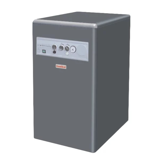
- Page 1 IST 03 C 201- 01 CAPRI C INSTALLATION, USE AND MAINTENANCE...
-
Page 2: Caution
Dear Customer, Thank you for choosing and buying one of our boilers. Please read these instructions carefully in order to install, operate, and maintain this equipment properly. -
Page 3: General Information For Installers, Service Engineers And User
General informations for installers, service engineers and users This INSTRUCTION MANUAL, Keep the packaging out of the In the event of long periods of which is an integral and indispen- reach of children as by its nature it inactivity of the boiler, disconnect sable part of the product, must be may represent a hazard. -
Page 4: Table Of Contents
INDICE Caution page 2 General information for installers, service engineers and user page 3 1 Instructions for the user page 5 1.1 Control panel page 5 1.2 How the heating unit operates page 6 1.2.1 Start-up page 6 1.2.2 Operation page 6 1.2.3 Unit shutdown page 6... -
Page 5: Instructions For The User
1. INSTRUCTIONS FOR THE USER 1.1 CONTROL PANEL pic. 1 1. Signalling light (red): when the red LED is illuminated 8. Indication light (red): when the light is on and fixed, it this means that the burner is blocked because the flame has indicates that the temperature of the water in the heating been extinguished. -
Page 6: How The Heating Unit Operates
1.2 Operating the boiler DOMESTIC HOT WATER 1.2.1 Switching on The domestic hot water function starts when the contact of the flow sensor closes and terminates when the same contact of the flow sensor opens. - Open the gas stop cock. The control card regulates the temperature of the domestic hot - Turn power mains switch to ON. -
Page 7: Burner Shutdown
1.2.3 Boiler shutdown Once the loading procedure is completed, fully close the inlet When the boiler malfunctions, the burner is automatically shu- tap. Should the tap not be properly closed, as pressure increa- ses, boiler CH safety valve may open and water flow out. tdown. -
Page 8: Technical Features And Dimensions
2 TECHNICAL CHARACTERISTICS AND DIMENSIONS Operator interface 2.1 Technical characteristics - General luminous switch This is an heating unit with a cast iron heat exchanger with three - SUMMER, WINTER, ANTI-FREEZE selector combustion gas passes that operates an oil-fired blown-air burner - Regulator of the temperature of the heating water and a DHW water tank. -
Page 9: Dimensions
2.2 Dimensions Air intake TFD version Fuel FLOW G 3/4 M supply D (mm) L (mm) G 1/2 M RETURN G 3/4 M CTFD COLD WATER G 1/2 M fig. 3 2.3 Plumbing diagram for the unit CH PROBE DHW PROBE CH PUMP DHW PUMP PRIORITY FLOW METER... -
Page 10: Unit Technical Data
2.4 Technical data of the heating unit MODEL Class of efficiency Heat input Qn 26.6 36.3 Heat output Pn 24.0 33.0 Efficiency at nominal load Efficiency at reduced load (30%) 89.7 90.7 No. of elements of the cast iron heat exchanger value 12.5 ÷... -
Page 11: Instructions For The Installer
3 INSTRUCTIONS FOR THE INSTALLER 3.1 Installation regulations 3.2.4 Connection to fuel oil mains supply Refer to subsection 4.3 for the instructions on how to connect the This is a heating unit which must be installed pursuant to applica- boiler to the fuel oil supply. ble standards and laws, which should be taken as incorporated in For heating units installed in areas that are particularly cold, use full in this manual. -
Page 12: Types And Classification Of Air Intake And Flue Gas Discharge Pipes
Version CTFD (type B23; C53; C83) model C23 Max equivalent length of discharge pipe Ø 120 mm: 5 metres The heating unit version CTFD (Types B23, C53 and C83) has a Each added wide radius 90° bend equals 1 metre discharge female fitting at the back with an 80 mm lip seal for connecting to Each added narrow radius 90°... -
Page 13: Measuring Combustion Efficency
3.2.8 Measuring combustion efficiency The hardness of the mains water determines how often the heat exchanger coil needs to be cleaned. Perform the following to determine combustion efficiency. - measure the combustion air temperature. ATTENTION - If the water is particularly hard it may be necessary to provide - measure the temperature of the flue gas and the percentage of taken through the holes in the flue gas duct. -
Page 14: Starting Up The Unit
3.4 Starting up the heating unit 3.4.2 Switching on and off 3.4.1 Preliminary checks For instructions on how to switch the heating unit on and off, refer to the “User Manual”. Before starting up the heating unit carry out the following checks: 3.4.3 Burner regulation - Make sure the flue gas discharge pipe and the air intake pipe are installed correctly. -
Page 15: Oil Burner
4 OIL BURNER 4.1 Description The heating unit is equipped with a single-stage oil burner bearing the CE mark and complying with EC Product Directives. 4.2 Mounting the burner on the heating unit The burner is mounted on the heating unit by means of an alumi- nium flange and held in position by a projecting screw and nut. -
Page 16: Regulating Combustion
Picture 19 shows a twin-pipe system. The burner performs best when the return pipe is immersed in the oil If oil is taken from a tank, the return pipe is must end at the same height as the uptake pipe. Picture 10 refers to a twin-pipe system. -
Page 17: Replacing The Control Unit
4 ± 0.3 mm 2 ÷ 2.5 mm pic. 13 4.7 Replacing the control unit Proceed as follows to replace the burner control unit (pic. 24). - Unscrew the screw 1, open the lid 2 and disconnect the wires. - Remove the coil 3. - Unscrew the two screws 4. -
Page 18: Wiring Diagram
4.9 Burner wiring diagram Picture 16 shows the wirin diagrams of the burners. Safety thermostat Limit thermostat Remote lock-out signal Ignition electrodes Flame detector Solenoid valve Burner-earth Capacitor Oil pre-heater pic. 16 4.10 Burner troubleshooting MALFUNCTION POSSIBLE CAUSE SOLUTIONS Check voltage at the terminals Boiler is not powered on Check the fuse The burner does not switch on when it... -
Page 19: Testing The Heating Unit
5 TESTING THE HEATING UNIT 5.1 Preliminary checks - Check that the safety valve is not blocked. - Check for water leaks. Before starting up the heating unit, carry out the following checks: - Make sure the heating unit has been installed in compliance with If the heating unit is not installed in compliance with the relevant legal requirements. -
Page 20: Trouble-Shooting
7 TROUBLE-SHOOTING UNIT STATUS MALFUNCTION POSSIBLE CAUSE SOLUTIONS The boiler is blocked, the red See paragraph See paragraph See paragraph blockage light 1 is illuminated. 4.10. “Burner diagnostic”. 4.10. “Burner trouble-shooting”. 4.10. “Burner trouble-shooting”. Water is not flowing in the CH system: pipes are clogged, thermostatic valves are closed, The boiler has shut down and... - Page 24 25079 VESTONE (Brescia) Italia - Via Cerreto, 40 Tel. 0365/878.31 e mail: fondital@fondital.it - www.fondital.it The manufacturer reserves the right to modify the data contained herein at any time without notice. Uff. Pubblicità Fondital IST 03 C 201 - 01 Maggio 2006 (05/2006)
Need help?
Do you have a question about the CAPRI C and is the answer not in the manual?
Questions and answers