
Related Manuals for Fondital ANTEA CTFS 13 AF


Summary of Contents for Fondital ANTEA CTFS 13 AF
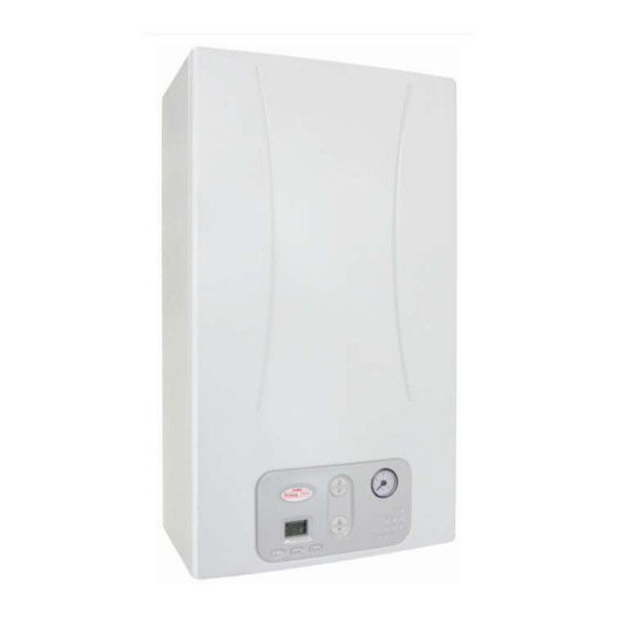
- Page 1 ANTEA Bi-thermal CTFS 13 AF CTN 13 AF INSTALLATION, USE AND MAINTENANCE Translation of the original instructions (in Italian)
- Page 2 Dear Sirs, thank You for choosing and buying one of our products. Please read these instructions carefully in order to properly install, operate, and maintain the product. WARNING We inform users that: • Boilers shall be installed by an authorised company under the requirements set forth by the prevailing rules, in full compliance with the prevailing regulations and standards.
- Page 3 General notes for installing and maintenance technicians, and users This instruction manual is an integral and essential part of the product. It shall be supplied by the installer to the user who shall keep it carefully to consult it whenever necessary. This document shall be supplied together with the equipment in case the latter is sold or transferred to others.
- Page 4 DANGER With gas fired boilers, take the following measures if you smell gas: • Do not turn on or off electric switches and do not turn on electric appliances. • Do not ignite flames and do not smoke. • Close the main gas cock. •...
-
Page 5: Table Of Contents
Instructions for the user ..........Control panel ............................8 Interpreting boiler status from display indications... - Page 6 Fig. 1 Control panel ................. Fig.
- Page 7 Tab. 1 CTFS 13 AF adjustment specifications ............Tab.
-
Page 8: Instructions For The User
1. Instructions for the user Control panel Fig. 1 Control panel A. Domestic hot water settings (+/- HOT WATER). B. Parameter confirmation and information request. C. Operating status selection. D. Alarm reset and back to the starting page during parameter selection. E. - Page 9 Ref. Description Steady on Flashing Displaying of the DHW temperature set- DHW indicator Boiler is in DHW mode. point. Indication of "parameter" inside the para- Parameter indicator Not used. meter menu. Temperature, parameter values and fault Alphanumeric indicator Not used. indication.
-
Page 10: Interpreting Boiler Status From Display Indications
Interpreting boiler status from display indications 1.2.1 Normal operation Boiler in STANDBY mode Boiler in SUMMER mode No active function Flow temperature displayed Boiler in WINTER mode No active function Flow temperature displayed Boiler in CENTRAL HEATING ONLY mode No active function Flow temperature displayed Boiler in SUMMER mode Domestic hot water withdrawal... -
Page 11: Boiler Operation
Boiler operation 1.3.1 Switching on DANGER It is presumed that the boiler has been installed by a qualified installer, it has been commissioned and is ready to operate correctly. • Open the gas shut-off cock. • Turn the master switch installed ahead of the boiler to ON. •... - Page 12 1.3.4 DHW function Boiler electronics always gives priority to DHW over CH supply. To set the domestic hot water temperature, press DHW +/- buttons. The DHW temperature setting range is from +35°C to +50°C. During temperature setting, the symbol flashes on the screen and the DHW current temperature setting is displayed. The burner ON symbol shows while the burner is operating.
-
Page 13: Boiler Shut-Down
1.3.9 Operation with (optional) remote control The boiler can also be connected to a Remote Control (optional - not compulsory, supplied by the manufacturer) so as to manage several boiler parameters, such as: • boiler status selection. • ambient temperature selection. •... - Page 14 1.4.4 Shut-down due to low water pressure Fault code E04 is displayed on the LCD display in the event of shut-down triggered by the water pressure switch. Fill the system by working on filler cock (A) (see Fig. 2 Filler cock). Water pressure must be 1÷1.3 bars while the boiler is cold.
-
Page 15: Maintenance
1.4.6 Alarm due to (optional) Remote Control connection malfunction The boiler recognises whether or not there is a Remote Control (optional, not compulsory). If the boiler does not receive information from the Remote Control after the Remote Control itself is connected, the boiler attempts to re-establish communication for 60 seconds, after which the fault code E31 is shown on the remote control display. -
Page 16: Technical Features And Dimensions
2. Technical features and dimensions Technical features The boiler is equipped with an integrated gas atmospheric burner. The following models are available: • CTFS sealed chamber, forced draught boiler with electronic ignition for heating and instantaneous DHW supply. • CTN open chamber, natural draught boiler with electronic ignition for heating and instantaneous DHW supply. - Page 17 2.1.3 Operating features • Electronic flame modulation in CH mode, with timed rising ramp. • Electronic flame modulation in DHW mode. • Flow freeze protection function: ON 5°C; OFF 30°C or after 15 minutes of operation if CH temperature > 5 °C. •...
-
Page 18: Dimensions
Dimensions CTFS Fig. 3 CTFS model dimensions Cold water inlet (1/2") Gas inlet (1/2”) CH system flow (3/4”) DHW outlet (1/2") CH system return (3/4”) Technical features and dimensions... - Page 19 Fig. 4 Model CTN dimensions Cold water inlet (1/2") Gas inlet (1/2”) CH system flow (3/4”) DHW outlet (1/2") CH system return (3/4”) Technical features and dimensions...
-
Page 20: Boiler Layouts
Boiler layouts CTFS Gas inlet CH system flow DHW outlet Cold water inlet CH system return Fig. 5 Boiler layout CTFS 1. DHW temperature probe 12. Pressure testing point on flue gas duct 2. Modulating gas valve 13. Air intake and flue gas venting duct 3. - Page 21 Gas inlet CH system flow DHW outlet Cold water inlet CH system return Fig. 6 Boiler layout CTN 1. DHW temperature probe 2. Modulating gas valve 3. CH return water temperature probe 4. Safety thermostat on CH flow 5. Burner 6.
-
Page 22: Operating Data
Operating data Burner pressures reported in the following page must be verified after the boiler has been operating for 3 minutes. Pressure at the burner Fuel Gas mains pressure [mbar] Nozzle [mm] [mbar] Natural gas G20 1,35 Natural gas G20 1,35 Butane gas G30 0,80... - Page 23 Description Value Heat loss from the boiler casing 2,04 Flue system heat loss with burner on 10,26 Flue system mass capacity 15,21 Flue temp. – air temp. °C CO2 value (methane/butane/propane) 3.0 / 3.6 / 3.0 Maximum heat output efficiency rating 87,7 Tab.
-
Page 24: Instructions For The Installer
3. Instructions for the installer Installation standards This boiler must be installed in compliance with the laws and standards in force in the country of installation, which are herein consi- dered as entirely transcribed. To find out about the gas category and technical specifications, refer to operation data and general features specified in the previous pages. - Page 25 DANGER Since the temperature of the walls on which the boiler is mounted and external temperature of coaxial air/flue gas system do not exceed 60°C, no minimum distance from flammable walls is to be accounted for. For boilers with split air intake and flue gas venting ducts, in the case of proximity with flammable walls and passages through walls, apply insulating material between the wall and the flue gas venting duct.
-
Page 26: Installing The Boiler
Installing the boiler DANGER Before connecting the boiler to CH and DHW networks, clean the pipes carefully. Before commissioning a NEW system, clean it to remove any metal chips due to machining and welding, and any oil and grease that might negatively affect boiler operation or even damage it in case they get inside it. Before commissioning a RECONDITIONED system (where radiators have been added, the boiler has been replaced, etc.) thoroughly clean it to remove any sludge and residues. -
Page 27: Air Intake And Flue Gas Venting System
Air intake and flue gas venting system Flue gas discharge into the atmosphere and air intake/flue gas venting systems must comply with applicable laws and standards in the country of installation that are considered as fully transcribed herein. DANGER The boiler is equipped with a safety device for flue gas exhaustion check. It is strictly forbidden to tamper with and/or prevent operation of such safety device. - Page 28 ≥ 2 Ø ≥ 2 Ø ≥ 3 % ≥ 3 % Ø Ø ≤ 1 m ≤ 1 m Fig. 8 Connections to the chimney of open chamber models Direct outside discharge Natural draught boilers can vent flue gas directly into the atmosphere via a duct which goes through the outside walls of the building and ends with an anti-wind gust device terminal.
- Page 29 3.6.2 Forced draught boiler When positioning the boiler exhaust terminals onto the wall, comply with the distances specified in the applicable standards and re- gulations in force in the Country of installation, which are herein considered as entirely transcribed. 3.6.3 Possible configuration of air intake and flue gas venting ducts Type B22 •...
- Page 30 Type C42 • Boiler intended for connection to collective chimney pipe sy- stem that includes two ducts, air intake and flue gas venting. These ducts may be coaxial or split. • The chimney must be compliant with applicable legislation and standards. Type C52 •...
- Page 31 3.6.4 Air intake and flue gas venting via 100/60 mm coaxial pipes Type C12 • Minimum permissible length of horizontal coaxial pipes is 1 meter. • Maximum permissible length of horizontal coaxial pipes is 6 metres. • For each additional 90° elbow, maximum permissible length is to be reduced by 1 meter. •...
- Page 32 Type C32 • Minimum permissible length for vertical coaxial pipes is 1 metre, equal to the length of the chimney. • Maximum permissible length for vertical coaxial pipes is 11 metres, including the chimney. • For each additional 90° elbow, maximum permissible length is to be reduced by 3 meters. •...
- Page 33 3.6.6 Air intake and flue gas venting via Ø 80 mm split pipes For all systems with separate air intake and flue gas vent pipes, the suitable standard split pipe kit (0SDOPPIA13) must be used, it includes two air deflectors, retaining screws, seals and the following parts: A.
- Page 34 The illustrations are indicative only. When installing accessories, refer to the instructions supplied with the accessories themselves. Configurations for 80 mm split air intake/flue gas venting pipes. Ø 80 (supplied with the boiler) Fig. 12 0SDOPPIA13 Fig. 13 Dimensions for split pipes 135 mm 45 mm 500 mm...
-
Page 35: Checking Combustion Efficiency
Checking combustion efficiency 3.7.1 Flue cleaning function • The boiler features a flue cleaning function which must be used to measure combustion efficiency during operation and to adjust the burner. • To activate the flue cleaning function, press and hold the buttons “Info” and “Reset” simultaneously for 5 seconds. The flow tempe- rature and the symbol are shown on the LCD. -
Page 36: Connection To Gas Mains
Connection to gas mains Cross-section gas pipe size must be chosen depending on its length, layout pattern, gas flow rate. Gas supply pipe cross-section must be equal or greater than boiler gas pipe. DANGER Comply with installation standards enforced in the country where the boiler is installed which are considered as fully transcribed in this booklet. -
Page 37: Connection To Electrical Mains
3.9.2 Prior to installing the boiler, the hydraulic system is to be cleaned in order to remove impurities; they could be present in system com- ponents and damage the pump and the heat exchanger. Cold water inlet and DHW outlet shall be connected to the boiler through the dedicated 1/2" F and C fittings (see Fig. 7 Paper tem- plate). -
Page 38: Installation And Operation With Open Therm Remote Control (Optional)
3.12 Installation and operation with Open Therm Remote Control (optional) WARNING Only use original Remote Control Units supplied by the manufacturer. The correct operation of the Remote Control itself and of the boiler is not guaranteed if non original Remote Control units not supplied by the manufacturer are used. -
Page 39: Tsp Parameters
3.13 TSP parameters The boiler operation is controlled by several parameters. To change parameters, press the Reset and - HEATING buttons together for 3 seconds. Scroll through the parameters by pressing CH +/- buttons. As soon as you reach the one to be modified, press ok. symbol turns on to indicate that you can edit the parameter value. - Page 40 Configurable Parameter Description Default values Notes value range Display of flow temperature n.a. n.a. n.a. Return temperature displaying n.a. n.a. n.a. DHW temperature displaying n.a. n.a. n.a. C = forced draught According to the Display of boiler type n.a. model B = natural draught Display of most recent boiler n.a.
-
Page 41: Filling The System
3.14 Filling the system Once all boiler connections have been completed, CH system can be filled. The procedure is to be cautiously carried out, following each step: • Open the bleeding valves on all radiators and verify the boiler automatic valve operation. •... -
Page 42: Starting Up The Boiler
3.15 Starting up the boiler 3.15.1 Preliminary checks Before starting the boiler, check that: • The flue gas venting duct and the relevant terminal are installed in conformity with the instructions: with the boiler operating, there must be no leakage of combustion by-products from any of the gaskets. •... -
Page 43: Wiring Diagrams
3.17 Wiring diagrams 0CREMOTO04 1 2 3 4 5 6 7 8 9 10 1112 SS SR SS SR FUSE 230 Vac 50 Hz CTFS Fig. 20 Wiring diagram Instructions for the installer... - Page 44 Internal connections DK : ..low water pressure swich SR : ..CH NTC flow probe 10k Ohm at 25°C B=3435 SRT : ..CH NTC return probe 10k Ohm at 25°C B=3435 SS : .
-
Page 45: Adaptation To Other Gas Types And Burner Adjustment
3.18 Adaptation to other gas types and burner adjustment WARNING This boiler is built to run on the type of gas specified on the packaging and on the boiler rating plate. Any later transformation is to be exclusively carried out by qualified personnel, using manufacturer designed accessori- es and following the procedure and adjustment instructions for an accurate boiler setting-up. - Page 46 3.18.3 Gas valve setting Maximum heating output adjustment • Check the flow pressure value (see Operating data on page 22); • Remove the plastic cover A at the top of the modulator coil, protecting the pressure regulator adjuster screws; • Connect a pressure gauge to the pressure measurement point IN to check the input OUT and the output pressure; •...
-
Page 47: Testing The Boiler
4. Testing the boiler Preliminary checks Before testing the boiler, it is recommended to check the following: • the flue gas venting duct and the relative terminal are installed in conformity with the instructions: there must be no leakage of combustion by-products from any of the gaskets. -
Page 48: Maintenance
5. Maintenance WARNING Any maintenance (and repair) work must only be carried out by qualified personnel. The user is strongly advised to have the product serviced and repaired by a service centre or qualified personnel. Appropriate boiler maintenance ensures efficient operation, environment preservation, and safety for people, animals and objects. Maintenance operations must be carried out at least once a year. -
Page 49: Combustion Analysis
Combustion analysis The combustion parameters of the boiler, which have to be checked in order to determine efficiency and emissions, must be measu- red in compliance with applicable legislation and standards. Maintenance... -
Page 50: Malfunctions, Possible Causes And Solutions
6. Malfunctions, possible causes and solutions Troubleshooting BOILER MALFUNCTION PROBABLE CAUSE USER'S TASKS QUALIFIED PERSON- STATUS NEL'S TASKS Check gas supply. Gas supply failure. Check gas supply cock or gas network safety valve intervention. Contact qualified person- Gas valve is disconnected. Reconnect it. - Page 51 BOILER MALFUNCTION PROBABLE CAUSE USER'S TASKS QUALIFIED PERSON- STATUS NEL'S TASKS Flue gas exhaust pressure Contact qualified person- Check pressure switch: switch is faulty replace it if faulty. The silicone pipes are Contact qualified person- Connect or replace silicone disconnected or damaged. pipes Flue gas pressure switch is Check air intake/flue gas...
- Page 52 BOILER MALFUNCTION PROBABLE CAUSE USER'S TASKS QUALIFIED PERSON- STATUS NEL'S TASKS Connector cable between Contact qualified person- boiler and remote control Reconnect it. No communication possi- disconnected. E31** ble with Remote Control. Contact qualified person- Remote control faulty. Replace it. Electronic board and gas Contact qualified person- Check connection to the...
- Page 53 Page left intentionally blank...
- Page 54 Page left intentionally blank...
- Page 55 Page left intentionally blank...
- Page 56 Fax +39 0365/878.304 e mail: info@fondital.it www.fondital.com The manufacturer reserves the right to modify his/her products as deemed necessary, without altering the basic characteristics of the products themselves. Uff. Pubblicità Fondital IST 03 C 871 - 03 | Dicembre 2018 (12/2018)
Need help?
Do you have a question about the ANTEA CTFS 13 AF and is the answer not in the manual?
Questions and answers