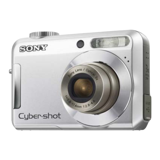
Sony Cyber-shot DSC-S650 Service Manual
Digital still camera
Hide thumbs
Also See for Cyber-shot DSC-S650:
- Manual pratique (103 pages) ,
- Handbook (101 pages) ,
- Instruction manual (64 pages)
Table of Contents
Advertisement
Quick Links
SERVICE MANUAL
Ver. 1.2 2007.06
Revision History
Revision History
How to use
How to use
Acrobat Reader
Acrobat Reader
Internal memory
Internal memory
ON BOARD
ON BOARD
Link
Link
SPECIFICATIONS
SERVICE NOTE
The components identified by
mark 0 or dotted line with
mark 0 are critical for safety.
Replace only with part num-
ber specified.
In case of the lens assembly, main board, or main frame assembly failure,
contact your local Sony Service Headquarter for the measures.
DSC-S650
9-852-182-11
DISASSEMBLY
BLOCK DIAGRAMS
Les composants identifiés par une
marque 0 sont critiques pour la
sécurité.
Ne les remplacer que par une pièce
portant le numéro spécifié.
Sony EMCS Co.
DSC-S650
Hong Kong Model
REPAIR PARTS LIST
DIGITAL STILL CAMERA
US Model
Canadian Model
AEP Model
UK Model
E Model
Australian Model
Chinese Model
Korea Model
Brazilian Model
Tourist Model
2007F0800-1
© 2007.06
Published by Kohda TEC
Advertisement
Table of Contents

Summary of Contents for Sony Cyber-shot DSC-S650
- Page 1 Ne les remplacer que par une pièce ber specified. portant le numéro spécifié. In case of the lens assembly, main board, or main frame assembly failure, contact your local Sony Service Headquarter for the measures. DIGITAL STILL CAMERA 2007F0800-1 DSC-S650 ©...
-
Page 2: Specifications
78 3/4 inches) (T) PRINT Image Matching III: Compatible PictBridge: Compatible [Input and Output connectors] (USB)•A/V OUT terminal: Design and specifications are subject to change Video, Audio (Monaural), USB without notice. communication USB communication: Full-Speed USB (USB 2.0 compliant) DSC-S650 — 2 —... - Page 3 CRITIQUES POUR LA SÉCURITÉ DE FONCTIONNEMENT. NE COMPONENTS WITH SONY PARTS WHOSE PART NUMBERS REMPLACER CES COMPOSANTS QUE PAR DES PIÈSES SONY APPEAR AS SHOWN IN THIS MANUAL OR IN SUPPLEMENTS DONT LES NUMÉROS SONT DONNÉS DANS CE MANUEL OU PUBLISHED BY SONY.
-
Page 4: Table Of Contents
3-1. Overall Block Diagram ··················································· 3-1 3-2. Power Block Diagram ····················································· 3-2 REPAIR PARTS LIST 4-1. Exploded Views ······························································· 4-1 4-1-1. Overall Section ······························································ 4-1 4-1-2. Front Block ··································································· 4-2 4-1-3. Main Frame Block ························································ 4-3 4-2. Accessories ······································································ 4-4 DSC-S650 — 4 —... -
Page 5: Service Note
1 Select [OK] with v on the control button, then press z. The message “All data in internal memory will be erased Ready?” appears. 2 Select [OK] with v, then press z. The format is complete. To cancel the formatting Select [Cancel] in step 1 or 2, then press z. DSC-S650... -
Page 6: Disassembly
3 Screw TP1.7 × 2 Screw TP1.4 4 Middle Cover (Right) × 3 Screw TP1.7 5 Middle Cover (Left) Assy × 4 Screw TP1.7 × 1 Screw TP1.4 2 Frame, SW 3 SW Board, Complete 4 Cabinet (Rear) Assy DSC-S650... - Page 7 5 Cabinet Front Assy 1 Lens Assy × 2 Screw TP1.4 1 Screw TP1.7 × 3 Strap Bracket × 2 Screw TP1.4 × 4 Screw TP1.4 3 ST Board, Complete 5 Battery Cover × 4 Screw TP1.7 6 Main Frame Assy DSC-S650...
-
Page 8: Block Diagrams
+3.1VD DGND +3.1VD DGND POWER GND_3 GND_2 BATT+1 BATT+1 MIC1 MIC1 SPM0204HD5 SPM0204HD5 MIC4_4.72X3.76_173 MIC4_4.72X3.76_173 G2412-0039-00 G2412-0039-00 AO8803 AO8803 G2013-0081-00 G2013-0081-00 SOP8_0.65_9 SOP8_0.65_9 BATT- 1 BATT- 1 1.6A/32V 1.6A/32V R131 R131 *10K *10K G2112-1002-00 G2112-1002-00 R0402 R0402 0.8A/24V 0.8A/24V DSC-S650... -
Page 9: Power Block Diagram
+3.3V +3.1VL PVDD 0.1UF 0.1UF 4.7UF 4.7UF AVDD +3.3V +3.1V LCD_BACKLIGHT +3.1VD 10UF 10UF 0.1UF X 2 0.1UF X 2 *3.3K *3.3K +3.1VD VCC2 *27.4 *27.4 10UF 10UF 0.1UF X 2 0.1UF X 2 SW BOARD +3.1VD BULE BULE DSC-S650... -
Page 10: Repair Parts List
3-106-991-01 MIDDLE COVER (RIGHT) 3-209-039-01 SCREW TP1.7*16 X-2177-476-1 CABINET (FRONT) ASSY 3-113-002-01 SCREW TP1.4*3 A-1249-951-A CABINET (UPPER) BLOCK ASSY 3-273-595-01 SCREW TP1.7*4.5 X-2177-477-1 MIDDLE COVER (LEFT) ASSY 3-106-992-01 LID, JK 3-209-036-01 SCREW TP1.7*3 3-106-990-01 LID, BT 3-209-038-01 SCREW TP1.4*2.5 DSC-S650... -
Page 11: Front Block
(Note 1) (Note 1) (Note 1) In case of the lens assembly, main board, or main frame assembly failure, contact your local Sony Service Headquarter for the measures. (Note 2) The adjustment is not required after replacing the ST block assembly. -
Page 12: Main Frame Block
4. REPAIR PARTS LIST 4-1-3. MAIN FRAME BLOCK Ref. No. Part No. Description 3-209-038-01 SCREW TP1.4*2.5 3-106-994-01 FRAME, SW A-1249-953-A FLEXIBLE BLOCK ASSY,SW X-2177-478-1 CABINET (REAR) ASSY DSC-S650... -
Page 13: Accessories
Owner’s Record The model and serial numbers are located on the bottom. Record the serial number in the space provided below. Refer to these numbers whenever you call upon your Sony dealer regarding this product. Model No. DSC-S650 Serial No. ___________________________ Wrist strap ©... - Page 14 [Regarding Fuse] • MCU BOARD Ref. No : MANUFACTURER: KAMAYA ELECTRIC CO.,LTD. TYPE: FCC16 162AD RATING: 1.6A Ref. No : MANUFACTURER: KAMAYA ELECTRIC CO.,LTD. TYPE: FCC10 801AD RATING: 800mA...
- Page 15 [Description of main button functions on toolbar of the Adobe Acrobat Reader Ver5.0 (for Windows)] Toolbar Printing a text Reversing the screens displayed once • To reverse the previous screens (operation) one by one, click 1. Click the Print button 2.
-
Page 16: Revision History
2007.01 Official Release — — 2007.02 Correction-1 • Correction of DISASSEMBLY (C1) S.M. Correction : Page 2-2 2007.06 Correction-2 • Correction of EXPLODED VIEWS (C2) • Change of part number for Instruction Manual S.M. Correction : Page 4-1, 4-4 DSC-S650...


