Table of Contents
Advertisement
SERIOUS
INJURY
OR
DEATH
COULD RESULT FROM IMPROP-
ER REPAIR OR SERVICE OF THIS
TOOL.
REPAIRS AND/OR SERVICE TO
THIS TOOL MUST ONLY BE PER-
FORMED BY AN AUTHORIZED
AND CERTIFIED DEALER.
Copyright © 2008, The Stanley Works
68369 3/2009 Ver 2
S
, O
AFETY
PERATION AND
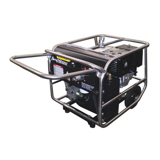
GT13
HYDRAULIC
POWER UNIT
M
USER'S MANUAL
Milwaukie OR 97267-5698
www.stanleyhydraulic.com
AINTENANCE
Stanley Hydraulic Tools
3810 SE Naef Road
503-659-5660
FAX 503-652-1780
Advertisement
Table of Contents
Troubleshooting

Related Manuals for Stanley GT13


Summary of Contents for Stanley GT13
- Page 1 THIS TOOL MUST ONLY BE PER- FORMED BY AN AUTHORIZED AND CERTIFIED DEALER. AFETY PERATION AND AINTENANCE USER’S MANUAL Stanley Hydraulic Tools 3810 SE Naef Road Milwaukie OR 97267-5698 503-659-5660 Copyright © 2008, The Stanley Works FAX 503-652-1780 68369 3/2009 Ver 2 www.stanleyhydraulic.com...
-
Page 3: Table Of Contents
REPAIRS AND / OR SERVICE TO THIS TOOL MUST ONLY BE DONE BY AN AUTHORIZED AND CERTIFIED DEALER. For the nearest authorized and certifi ed dealer, call Stanley Hydraulic Tools at the number listed on the back of this manual and ask for a Customer Service Representative. -
Page 4: Safety Symbols
SAFETY SYMBOLS Safety symbols and signal words, as shown below, are used to emphasize all operator, maintenance and repair actions which, if not strictly followed, could result in a life-threatening situation, bodily injury or damage to equip- ment. This is the safety alert symbol. It is used to alert you to potential personal injury hazards. -
Page 5: Safety Precautions
In addition to this manual, read and understand safety and operating instructions in the Engine Operation Manual furnished with the power unit. The GT13 Hydraulic Power Unit will provide safe and dependable service if operated in accordance with the instructions given in this manual. Read and understand this manual and any stickers and tags attached to the Power Unit. -
Page 6: Tool Stickers & Tags
TOOL STICKERS & TAGS 68321 Power Unit Dash Decal... -
Page 7: Hydraulic Hose Requirements
HOSE SAFETY TAGS To help ensure your safety, the following DANGER tags are attached to all hose purchased from Stanley Hydrau- lic Tools. DO NOT REMOVE THESE TAGS. -
Page 9: Htma Requirements
HTMA REQUIREMENTS TOOL CATEGORY HYDRAULIC SYSTEM REQUIREMENTS TYPE I TYPEII TYPEIII TYPE RR FLOW RATE 4-6 gpm 7-9 gpm 11-13 gpm 9-10.5 gpm (15-23 lpm) (26-34 lpm) (42-49 lpm) (34-40 lpm) TOOL OPERATING PRESSURE 2000 psi 2000 psi 2000 psi 2000 psi (at the power supply outlet) (138 bar) -
Page 10: Operation
OPERATION These fl uids are recommended by Stanley. Other fl uids PREPARATION FOR USE that meet or exceed the specifi cations of these fl uids may also be used. Do not operate the power unit until you have read the... - Page 11 OPERATION CONTROLS CONTROL PANEL The Power Unit provides one circuit, with an oil fl ow of 7 gpm/26 lpm up to 2000 psi/140 bar. RETURN PRESSURE H.T.M.A. 1/2 INCH FE- MALE QUICK DISCON- NECT COUPLER H.T.M.A. 1/2 INCH MALE QUICK DISCONNECT COUPLER Figure 3.
- Page 12 OPERATION Manual Throttle Control is set by positioning the knob • When operating drills or grinders or pumps, tool rpm must be maintained even when load requirements are (shown in fi gure 4.) to the far left and tightening it to main- light.
- Page 13 OPERATION 5. Move the choke lever to the CLOSED position as shown and 10. in fi gure 6. 11. Set the throttle control for "automatic" or "manual" operation. 12.Move the tool circuit control lever to the ON position. When fi nished operating the tool, move the tool circuit con- trol lever to the OFF positon.
-
Page 14: Routine Maintenance
ROUTINE MAINTENANCE ENGINE MAINTENANCE STORAGE Follow the maintenance schedule and general maintenance • Clean the unit thoroughly before storage. Do not use instructions in the engine maintenance and operation water pressure. manual furnished with the power unit. • Always store the unit in a clean and dry facility. HYDRAULIC SYSTEM MAINTENANCE •... -
Page 15: Testing & Troubleshooting
1. Set the throttle control knob to the automatic position. clockwise to raise the pressure and counterclockwise to reduce the pressure. 2. Connect the Stanley Circuit Tester across the hose ends (where the tool would normally be connected). c. Tighten the nut and retest. -
Page 16: Troubleshooting
TROUBLESHOOTING PROBLEM CAUSE REMEDY Engine will not start. No fuel. Add Fuel. Fuel fi lter plugged. Replace fuel fi lter. Defective spark plug. Remove plug, check gap, clean or replace. Fluid blowing out of fl uid Hydraulic tank overfi lled. Correct the fl... -
Page 17: Specifi Cations
SPECIFICATIONS Engine: ...............................Honda GX390 4 stroke Horsepower ..................................11 Capacity............................One 7 gpm/26 lpm Circuit Length:...............................26.25 in. / 66.7 cm Width: ................................20.75 in. / 52.7 cm Height: ................................21.25 in. / 54 cm Weight (Wet): ...........................162 lb / 73.5 kg Fuel Tank Capacity: ............................1.6 gal. / 6.1 ltr Hydraulic Reservor Capacity: .......................... -
Page 18: Parts Lists & Illustrations
GT13 PARTS ILLUSTRATION... - Page 19 GT13 PARTS ILLUSTRATION CONTINUED Wheel to Frame Placement Engine mounting...
- Page 20 GT13 PARTS LIST Item Part No. Qty Description Item Part No. Qty Description 68353 2 Capscrew 68355 1 Hose Assy 67464 1 Rod End 02633 1 Knob 68324 1 67329 1 Hose Assy 00026 1 O-ring 350036 1 Elbow 67541 1...
-
Page 21: Warranty
fi rst retail purchaser, or for a period of 2 years from the shipping date from Stanley, whichever period expires fi rst, to be free of defects in material and/or workmanship at the time of delivery, and will, at its option, repair or replace any tool or part of a tool, or new part, which is found upon examination by a Stanley authorized service outlet or by Stanley’s factory in Milwaukie, Oregon to be DEFECTIVE IN MATERIAL AND/OR WORKMANSHIP. - Page 22 Stanley Hydraulic Tools 3810 SE Naef Road Milwaukie, Oregon 503-659-5660 / Fax 503-652-1780 www.stanleyhydraulic.com...
Need help?
Do you have a question about the GT13 and is the answer not in the manual?
Questions and answers