Nexo NXES104 User Manual

Nexo NXES104 User Manual

Powered tdcontrollers digital patching unit digital meters unit
Table of Contents

Advertisement

NXAMP4x1 & NXAMP4x4
Powered TDcontrollers
Digital Patching Unit
Digital Meters Unit
NXES104 / NXDT104
User Manual v2.8 (LOAD3_15)

Advertisement

Table of Contents
loading
Need help?

Need help?

Do you have a question about the NXES104 and is the answer not in the manual?

Questions and answers

Summary of Contents for Nexo NXES104

  • Page 1 NXAMP4x1 & NXAMP4x4 Powered TDcontrollers Digital Patching Unit Digital Meters Unit NXES104 / NXDT104 User Manual v2.8 (LOAD3_15)
  • Page 3: Fcc Information (U.s.a.)

    FCC requirements. Modifications not expressly approved by which can be determined by turning the unit “OFF” and “ON”, please try to NEXO-SA may void your authority, granted by the FCC, to use the product. eliminate the problem by using one of the following measures: 2.
  • Page 4: Power Supply/Power Cord

    • Do not open the device or attempt to disassemble the internal parts or modify them from the outlet, and have the device inspected by qualified NEXO-SA service in any way. The device contains no user-serviceable parts. If it should appear to be personnel.
  • Page 5: Important Notice For The United Kingdom

    • Always turn the power off when the device is not in use. • The performance of components with moving contacts, such as switches, volume controls, and connectors, deteriorates over time. Consult qualified NEXO-SA service personnel about replacing defective components.
  • Page 6: Table Of Contents

    TABLE OF CONTENT TABLE OF CONTENT FCC INFORMATION (U.S.A.) ............................3 IMPORTANT SAFETY INSTRUCTIONS......................... 3 PRECAUTIONS..................................3 ..............................4 OWER SUPPLY OWER CORD .................................... 4 O NOT OPEN ..................................4 ATER WARNING ............................4 F YOU NOTICE ANY ABNORMALITY ..............................4 OWER SUPPLY OWER CORD ....................................
  • Page 7 TABLE OF CONTENT (9) C ...............................17 HANNEL INDICATORS (10) A ..................................17 IR INTAKES (11) S ............................17 CREW HOLES FOR HANDLES ..............................18 ACK PANELS DESCRIPTION (1) M ................................18 AINS CONNECTORS (2) B ..........................18 ALANCED AUDIO INPUTS WITH LINK (3) E ................................19 XPANSION SLOT (4) P ................................19...
  • Page 8 ................................74 YSTEM ALIGNMENT ..............................75 EOMETRICAL ALIGNMENT ................... 75 EASURING AND ALIGNING PHASE IN THE OVERLAPPING REGION NXES104 EXPANSION BOARD, REMOTE CONTROL AND ASIO DRIVER ............77 NXES104 P ............................77 HYSICAL DESCRIPTION (1) E ™ IN P ..............................78...
  • Page 9 TABLE OF CONTENT .......................................80 ....................................80 WITCHES LAN..................................80 IRELESS ..................................81 THERNET CABLES ....................................83 IBER PTIC NXAMP ............................83 NSTALLATION INSIDE THE NXAMP NXES104 ™ ................83 WITH CONTROL PAGE IN MONITOR SOFTWARE ................................84 OMPATIBILITY ISSUES ..............................84 RAPHICAL USER INTERFACE (1) V ..............................85 IRTUAL FRONT PANEL (2) I ..................................85...
  • Page 10 INKING SEVERAL TOGETHER NXWIN4 SOFTWARE FOR NXAMP FIRMWARE UPGRADE................119 NXAMP........................119 HAT YOU NEED TO UPGRADE YOUR ................................119 ERIAL PORT UPGRADE NXES104 NXDT104) ....................120 ETWORK PORT UPGRADE FROM NXAMP ........................120 ONNECT THE COMPUTER TO THE (1) R ES100 ..............................
  • Page 11 TABLE OF CONTENT DMU TECHNICAL SPECIFICATIONS ........................129 DPU TECHNICAL SPECIFICATIONS..........................129 DMU DIMENSIONS................................130 DPU DIMENSIONS ................................130 NXES104 & NXDT104 TECHNICAL SPECIFICATIONS...................131 APPLICATION NOTE: DRIVING THE SUB FROM THE AUX SEND..............132 MAIN ? ...........132 HAT IS THE PHASE RELATION BETWEEN THE OUTPUT OF YOUR MAIN ? ...................132...
  • Page 12: Nxamp Versus Nx242: What's New

    NXAMP VERSUS NX242: WHAT’S NEW? NXAMP versus NX242: What’s new? The NXAMP Powered TDcontroller has been designed in order to provide ascendant compatibility with its predecessor – the NX242 Digital TDcontroller. What’s remaining the same? DSP core The DSP used in the NXAMP are from the same family (same core) than the one used in NX242 and on the NXTENSION board.
  • Page 13: Computing Resources

    2x 64 channels Ethersound™ ES100 network. This optional board uses the new NEXO slot which prevents the necessity to open the top panel of the amplifier for installing the board. NXAMP firmware upgrade can also be performed through this Ethersound™...
  • Page 14: Optional Dmu Unit

    The DPU (Digital Patching Unit) is an optional 1U device that can be used together with the NXAMP powered TDcontroller to ease the patching of any Nexo speaker. This unit will automatically route the amplifier output channels to the correct pins pair of the Speakon 4 or Speakon 8 connectors on its front panel.
  • Page 15: Quick Start

    This section will allow you to quickly understand the basic functions of this product. If you already know the previous NEXO digital TDcontrollers, such as NX241 or NX242, you may be able to use the NXAMP Powered TDcontroller quickly as it has been designed with a similar user interface.
  • Page 16: Lcd Display

    QUICK START Stand-by mode consumes slightly more current than in Power off mode, but allows the amplifier to be brought back from Stand-by to power on mode through remote control. The last LED, ‘Amp Protect’ reflects the protection status of the amplifier. If this LED is lit, it signifies that the amplifier is reducing or muting one or several outputs due to malfunctions as overheating, output DC, short circuitry …...
  • Page 17: Channel Indicators

    QUICK START (9) Channel indicators For each channel, you have three LEDs indicator. The ‘Sense’ LED will light to green when a certain level of current is detected on the output, meaning that a cabinet is connected and that some signal is flowing to it. The ‘Protect’ LED will light to yellow if the TDcontroller is applying a VCEQ protection on that channel (see further for details).
  • Page 18: Back Panels Description

    QUICK START Back panels description (1) Mains connectors This is the mains input for the NXAMP. There is one mains plug on NXAMP4x1 and two mains plug on NXAMP4x4. • On NXAMP4x1, the plug is a Powercon 20A for the 100 ~ 120 Volts model (ref. NXAMP4x1U) and a standard IEC 3 pin for the 220 Volts model (ref.
  • Page 19: Expansion Slot

    (5) RS-232 port Through this serial port, you can upload a new firmware, which adds new functionalities and new cabinets’ setups, or connect a NEXO DPU (Digital Patching Unit) device. See further for details about the update procedure and the DPU connection.
  • Page 20: Gpio Port

    (6) GPIO port This GPIO port is used for interfacing the amplifier to security system, or to allow a basic remote control of the unit. NEXO DMU (Digital Meters Unit) device also connects here. (7) Rear end mounting holes If the NXAMP is to be rack mounted and transported frequently, be sure to support the rear end of the unit with mounting hardware that matches the size of the rack used.
  • Page 21: Select Your Cabinet Set-Up

    QUICK START Select your cabinet set-up In the Options menu, choose Systm Config, and you will be able to choose among the different set-ups within the same cabinet family. (i.e. you don't have to modify the amplifier to cabinet wiring). Press All button and all setups will be available for selection. Using the amplifier without the TDcontroller functionality If you want to use the amplifier without the TDcontroller, just choose the “FLAT mode”...
  • Page 22: What's Inside The Carton Box

    • 1 x Mains cord (for NXAMP4x1) or 2 x Mains cord (for NXAMP4x4) • 1 x CD-ROM containing manuals and product brochures for the whole NEXO range. N.B.: The provided mains cord is Chinese type for NXAMP4x1C or NXAMP4x4C (220 ~ 240 Volts version) and US type for NXAMP4x1U or NXAMP4x4U (100 ~ 120 Volts version) or NXAMP4x4W (110 ~ 120 / 220 ~ 240 Volts version).
  • Page 23: Setting-Up Advice

    Mains setting NEXO NXAMP Powered TDcontrollers exists under two references for NXAMP4x1 and three references for NXAMP4x4: NXAMP Reference Mains Voltage...
  • Page 24: Mounting The Nxamp In A Rack (Grounding, Shielding & Safety Issues)

    SETTING-UP ADVICE For the NXAMP4x4W this is slightly different; the unit is sensing the mains voltage on power up, and then will choose to boot either in “110 Volts” mode or “220 Volts” mode. Once the NXAMP4x4W has startup up in one of the two modes, it will be locked to the corresponding voltage range till next power up.
  • Page 25 SETTING-UP ADVICE NXAMP4x1 rack holes position NXAMP4x4 rack holes position With NXAMP4x1, because of this layout, it is not possible to use some rack rails with 2 holes per rack unit (see picture bellow), because you will loose ½ U of rack space on the top and bottom of the amplifier.
  • Page 26: Using The Nxamp Without A Rack

    Powered TDcontroller has malfunctioned. This fuse must only be changed by NEXO certified service personnel. In any case do not replace the fuse with a non-certified NEXO fuse, as this will invalidate the NEXO warranty.
  • Page 27 SETTING-UP ADVICE TDcontroller can sustain high current in pin 1 without degradation of output noise. We recommend that the sources and loads you use have the same desirable characteristics. It is sometimes claimed that connecting cable shield at both ends creates ground loops, and that the current flowing in such loops will produce noise.
  • Page 28: Nxamp Power Outputs Wiring

    SETTING-UP ADVICE NXAMP power outputs wiring NEXO recommends the exclusive use of multi-conductor cables to connect the system: the cable kit is compatible with all the cabinets, and there is no possible confusion between LF, MF and HF sections. Cable choice consists mainly of selecting cables of the correct sectional dimension (size) in relation to the load resistance and the cable length.
  • Page 29: General Description

    GENERAL DESCRIPTION GENERAL DESCRIPTION Global architecture NXAMP4x1 Global architecture The diagram bellow shows the global architecture of the NXAMP4x1 amplifier. NXAMP4x4 Global architecture The diagram bellow shows the global architecture of the NXAMP4x4 amplifier. PAGE 29 OF 140...
  • Page 30: Power Supply Block

    GENERAL DESCRIPTION Power Supply Block Power Supply is certainly the most important part of an amplifier. Most of the time, the Power supply is limiting the power of an amplifier, more than the amplifying circuit itself. • On NXAMP4x1, two large power supplies are used, one for channel (1 and 2) and the other for channel (3 and 4).
  • Page 31: Analog Input Block

    GENERAL DESCRIPTION They all are full resonant type with half bridge converter. The ZCS (Zero Current Switching) design ensures high efficiency and low noise. Moreover, because the two converters work in opposite phase, some noise is cancelled; this is preferable for both sound quality and EMC (Electro magnetic compatibility).
  • Page 32: Power Amplifier Blocks

    These data will be used by the DSP for protecting both the amplifier and the NEXO loudspeaker connected. This stage features also a programmable routing unit that allows using the amplifier in bridge mode on the same speakon pins than in non bridge mode.
  • Page 33: User Interface Block

    The RS232 port is mainly used to upgrade the firmware of the unit from a PC computer, or to connect a NEXO DPU (Digital Patching Unit). The pin-out is given bellow: The RxD pin is the “Receive data” pin from the NXAMP point of view. Thus this is an input.
  • Page 34: Expansion Slot Block

    At the moment, there is two expansion boards available, the NXES104 Ethersound™ board and the NXDT104 Dante™ board. The NXES104 is compatible with the ES-100 standard, offering full remote control from a computer running ES monitor by Auvitran application, and 4 channels of 24 bits 48 KHz audio, from an ES network or from a PC computer through a LAN network using the Auvitran ASIO streamer technology.
  • Page 35 GENERAL DESCRIPTION NEXO expansion slot form factor is not compatible with the Yamaha mini-YGDAI form factor. Thus, Yamaha mini-YGDAI card cannot be fitted inside NXAMP Powered TDcontroller. Since July 2009, all NXAMP4x1s and NXAMP4x4s are shipped with an expansion card fitted in, the NX-DFLT card.
  • Page 36: Block Diagram Description

    BLOCK DIAGRAM DESCRIPTION Block diagram description The block diagram bellow shows the global signal path inside the DSPs, for one channel (identical for all the channels): The detail of each block numbered is given bellow. PAGE 36 OF 140...
  • Page 37: Patching And Routing (1)

    BLOCK DIAGRAM DESCRIPTION Patching and routing (1) Basically, any combination of the four XLR analog inputs (numbered A to D on the back panel) can be patched to each channel of the amplifier. If an expansion board is fitted, the four added digital input (numbered E to H) can be mixed as well.
  • Page 38: Equalising Wideband Acoustical Response (3)

    BLOCK DIAGRAM DESCRIPTION The high pass filters are also extremely important as they optimise excursion at very low frequency which is a very important safety factor. (Therefore do not use set-ups which are not designed for the cabinet you are using). Equalising wideband acoustical response (3) This wideband equaliser section achieves the correction required to obtain a flat system response, as the cabinets are acoustically designed for maximum efficiency on the whole...
  • Page 39: Protections

    BLOCK DIAGRAM DESCRIPTION The NXAMP TDcontroller will limit the user gain adjustment to a group of channel in specific case such as cardioids setups (for example on CD18 setup, gain is linked between front and rear loudspeaker). Protections Each channel has its own simulation and protection process. Each audio channel contains a combination of controlled gain stages (let's call them VCA’s as in our analogue circuitry).
  • Page 40: Hf Displacement Control (12)

    BLOCK DIAGRAM DESCRIPTION particular area (this is block (10)). As with displacement VCEQ, another set of mechanical stress VCEQ is needed for band-pass cabinets (this is block (11)). HF displacement control (12) In case of passive setups, a channel will deal with several loudspeakers after passing through the passive filter of the cabinet.
  • Page 41: Interchannel Regulation (19)

    BLOCK DIAGRAM DESCRIPTION The so-called Physiologic Dynamic Control (see block diagram) is intended to avoid unwanted effects as a result of a too long attack time constant. By anticipating the operation of the temperature limiter, it prevents a high level Audio signal appearing suddenly then being kept up for a period, which is long enough to trigger the temperature limiter.
  • Page 42: Menu Description

    0. FLAT - NO PROTN. [4 ch amplifier] If the current setup does not match any of the provided NEXO setup (i.e. the NXAMP is running a custom setup) the default display will show the ca binet selection each channel.
  • Page 43: Changing Cabinet Family

    [4 ch amplifier] Changing Cabinet Family In order to prevent end-user changing between different NEXO systems set-ups during use, the following procedure is recommended. This procedure has been purposely designed to avoid any mistakes. It is nevertheless very easy to change set-up among the same family or between families (see further, “System config”).
  • Page 44: Adjusting Volume

    MENU DESCRIPTION Adjusting Volume The volume of each channel can be adjusted from the Volume menu (unit is dB). Bellow is a picture of this menu. The volume setting for each channel can always be clearly seen from the front panel surrounding LED (white/blue) around each mute button.
  • Page 45: Adjusting Delay

    MENU DESCRIPTION NB: You can adjust large differences of gain between channels with the volume menu. There is no difference between gain and volume setting; this distinction is only done by analogy with traditional amplifiers. The CPU will always check gain, volume, patch and headroom settings and decide what the best combination is between analog or digital gain to optimize the dynamic range of the system.
  • Page 46: Adjusting Array Eq

    MENU DESCRIPTION The gain value can be read on the top of the LCD screen for each channel (unit is dB). To change the gain for a channel, select it first by pressing the corresponding ‘Select’ button. The channel name on screen will then be put between bracket (on picture above, CH2 is selected).
  • Page 47: Adjusting Headroom

    MENU DESCRIPTION corresponding ‘Select’ button. The channel name on screen will then be put between bracket (see on the picture above, channel 2 is selected). Then turn the wheel to change the Array EQ setting (from – 6 dB to + 6 dB). You can select multiple channels by pressing several ‘Select’...
  • Page 48 MENU DESCRIPTION With heavy content, like open air rock concert, you will need the full input range sensitivity. This is the most typical situation. In that case, the headroom should be adjusted to 0 dB. Default headroom position (0 dB) situation : Max input level Max Output Level Analog A...
  • Page 49: Options Menu

    (Wideband and Crossover for example) without restarting the amplifier. You can also build you own setup by selecting on each channel which NEXO speaker you want to connect. Moreover, you can choose for each output the crossover point you want to use for this speaker (crossover options are different regarding the selected speaker).
  • Page 50 Turn the wheel to make your choice blink on the first line of the screen, then press the “B” button. Nexo config Select one speaker setup by turning the wheel till the setup number appears blinking on the LCD screen (in this example, you can toggle between the Crossover (Xover) and the Wide setup).
  • Page 51 MENU DESCRIPTION Custom config When entering the Custom config menu, the first display shows the current setup for the selected output (including speaker name, variant and crossover points(s) if available). You can display the current setup information for each output by depressing the corresponding ‘Select’...
  • Page 52 MENU DESCRIPTION Once the bridge mode has been selected (or not in our example) you will be prompt to choose among various speaker mode if available. In the case of the PS15R2, the mode is either “Normal” or “MON” for Monitoring application. Let’s select the standard mode in this example.
  • Page 53 MENU DESCRIPTION Now you can choose between one of the following solutions: Either you enter the other channel and setup the speaker you wish, or you can copy the setup from any channel to one, two or three other channels. To do this first keep the Select button down for the “Master”...
  • Page 54: Input Patch

    MENU DESCRIPTION By depressing the cancel sign (‘x’) the display is now back to default mode; if the chosen setups are equivalent to a known “Nexo setup”, then the default display is the classical one, like displayed on the following picture: If the chosen setups does not match any of the NEXO four channels setups (including chosen crossover frequency) the display will show the speaker selected for each output.
  • Page 55 MENU DESCRIPTION to have same signal feeding two channels of amplifier or more. In this situation, changing the patch for one channel will automatically affect the other channels. First step to change the input patch is to go to the OPTION menu (see above). Then select the sub-menu 2.Input Patch.
  • Page 56 MENU DESCRIPTION Then a blank display is inserted, and the first display (routing to “PS10R2”) is displayed again. Now another example using the setup PS10R2 (2-4) and LS600 (1-3). In that case, the main and the sub are supposed to share the same speakon cable. The ‘Input Patch’ sub menu in the “Options”...
  • Page 57 MENU DESCRIPTION Then a blank display appears to display clearly the limit between the two speakers’ parameters. Now the display of the second speaker connected to these output speakon can start: PAGE 57 OF 140...
  • Page 58 MENU DESCRIPTION And the loop can start again. NB: The ‘classical’ PS10R2 + LS600 setup also available allow using independent cable for each output if needed (Speakon A and B for 2 x LS600 and Speakon C and D for 2 x PS10R2).
  • Page 59: Save/Recall User Setups

    MENU DESCRIPTION Any combination of input can be patched on each output. Be careful when patching both analog and digital input together to one channel: It is very unlikely that the two signals can be in phase. We recommend using this solution only for analog backup of digital network, meaning that only digital or analog inputs will be used at a time.
  • Page 60 MENU DESCRIPTION Once the button “Save” has been pressed, you will be requested to enter the name for that user setup (default name is USERSET followed by the setup number). Starting from the first character, turn the wheel to choose a letter, and then depress the ‘Select 4’ (for “Next”) button to go to the next letter.
  • Page 61: Security

    MENU DESCRIPTION At the end of the recall, the default display is shown on the LCD screen. Security The menu allows locking the local control or the remote control of the NXAMP. To access the Security menu, go to the Option menu, and select the sub-menu 4. Security (see above).
  • Page 62: Gpio Mode

    MENU DESCRIPTION To change either the local or the remote control access, press the corresponding ‘Select 2’ (for local control) or ‘Select 4’ (for remote control) button. If the password has not been entered yet, it will be asked now. Password ? Control Prev...
  • Page 63 NXAMP when they are located in the same rack. GPIO mode 0 (Default mode / DMU mode) In this default mode the GPIO port can be used with a NEXO DMU unit. See further in this manual for more details about DMU set up.
  • Page 64 MENU DESCRIPTION Meaning when set to 0 Pin Name In/Out Meaning when set to 1 (Default) GPInput 1 CH 1 unmuted CH 1 muted GPInput 2 CH 2 unmuted CH 2 muted GPInput 3 CH 3 unmuted CH 3 muted GPInput 4 CH 4 unmuted CH 4 muted...
  • Page 65 MENU DESCRIPTION Meaning when set to 0 Pin Name In/Out Meaning when set to 1 (Default) GPInput 1 Power amp can start Do not start power amp GPInput 2 Analog input unmuted Analog input muted GPInput 3 Digital input muted Digital input unmuted GPInput 4 Scene 1 is recalled...
  • Page 66 MENU DESCRIPTION GPIO mode 3 (CP4SW simple remote mode) This mode is intended to be used with momentary ‘High’ signals (like push buttons). It is recommended to use the Yamaha CP4SW remote control panel for DME. Connect the button 1 to 4 to the GPI 1 to 4, and each LED to GPO 1 to 4. Here is the detail: Pin Name In/Out On each Impulse (From 0 to 1 and back to 0)
  • Page 67 MENU DESCRIPTION GPOutput4 is blinking each time a decrease volume command is received, and is ON when volume is set to min. GPOutput5 reflects the GPInput1 (with a small delay and without glitches). GPOutput6 reflects the GPInput2 (with a small delay and without glitches). GPOutput7 reflects the GPInput3 (with a small delay and without glitches).
  • Page 68 MENU DESCRIPTION GPOutput1 is ON when setup 1 has been recalled. GPOutput2 is ON when setup 2 has been recalled. GPOutput3 is ON when setup 3 has been recalled. GPOutput4 is ON when setup 4 has been recalled. GPOutput5 reflects the GPInput1 (with a small delay and without glitches). GPOutput6 reflects the GPInput2 (with a small delay and without glitches).
  • Page 69 MENU DESCRIPTION If GPInput1 is ‘High’, Channel 1 will be muted. If GPInput1 is ‘Low’, Channel 1 will be unmuted. Front Panel mute/Unmute is still working. If GPInput2 is ‘High’, Channel 2 will be muted. If GPInput2 is ‘Low’, Channel 2 will be unmuted.
  • Page 70: Load Monitor

    MENU DESCRIPTION Load Monitor This menu allows setting up the NXAMP impedance monitoring function, which allows to report (through its GPIO port of through the Ethersound network) if the speakers are correctly connected to the amplifier and ready to be used. This is particularly useful for safety installations where the status of the connected speakers should always be known, and any default in the audio chain should be reported.
  • Page 71 MENU DESCRIPTION If external pilot tone is used (from the audio program sent to the NXAMP on its analog or digital inputs), be sure that the frequency selected here is as close as possible to the frequency of the pilot tone. (2) Internal HF burst generator level The level of the internal HF burst generator can be adjusted here.
  • Page 72: Miscellaneous

    MENU DESCRIPTION (7) Measured impedance The measured impedance of the channel selected in zone 6 is displayed here. The display is one of the following: 1) If the NXAMP is unable to measure the impedance of the speaker (for example channel is muted or no speaker connected, or no pilot tone at the selected frequency), “Z= ?? Ω”...
  • Page 73 MENU DESCRIPTION To change the current delay unit, press Edit (‘Select 4’ button) and turn the wheel up or down to the selected unit. The available options are milliseconds (ms), meters or inches. Once done, press OK (‘Select 4’ button) to validate you choice. Dante Id This sub menu allows changing the Dante™...
  • Page 74: Installation Recommendations

    NEXO strongly recommends avoiding use of such devices. N.B.: Do not use NEXO’s TDcontrollers (Analog or Digital) to feed the inputs of the NXAMP as this processing is already included inside the NXAMP.
  • Page 75: Geometrical Alignment

    INSTALLATION RECOMMENDATIONS (see example below) We recommend that the system is adjusted so that arrivals from MAIN SYSTEM array and SUB speakers are coincident at a fairly distant listening position (typically further than the mixing position). Geometrical alignment In the example below, r being the smaller distance from MAIN SYSTEM array to listener position, and r being the smaller distance from SUB to listener position, the distance...
  • Page 76 INSTALLATION RECOMMENDATIONS displayed in the low-frequency range. If the MAIN SYSTEM phase reading appears to be superior to the SUB phase reading, then MAIN SYSTEM will have to be delayed with a value close to the one given by the geometrical alignment.
  • Page 77: 
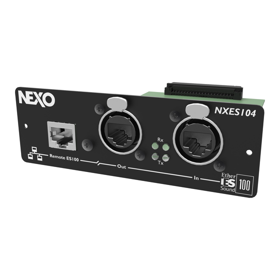
Nxes104 Expansion Board, Remote Control And Asio Driver

    NXAMP is updated (see further in this manual). NXES104 Physical description The NXES104 is designed to fit the NEXO’s slot form factor that can be located on the back panel of the NXAMP Powered TDcontrollers. NB: This slot features an 80-pins internal connector that is not compatible with the Yamaha mini-YGDAI slot.
  • Page 78: Ethersound In Port

    NXES104 EXPANSION BOARD, REMOTE CONTROL AND ASIO DRIVER ™ (1) Ethersound IN Port This port features and Ethercon® connector. Use this type of connector to secure your Ethersound™ network from unwanted unplugs. This type of connector also ensures a longer life to the internal RJ45 contacts, because it preserves it from external traction.
  • Page 79: Various Ethersound™ Devices Description

    Optionally, a 3 Ethernet port can be added on the ES100 device (this is the “Remote ES100 port” that you can find on the NXES104). From this port you can take control over the connected device, but also over the whole Ethersound™...
  • Page 80: Es100/Spkr Devices

    NXES104 EXPANSION BOARD, REMOTE CONTROL AND ASIO DRIVER ES100/spkr devices The ES100/spkr implementation is a light implementation of the ES100 above: ES100/spkr is compatible only with mono-directional Ethersound™ network, and can only extract a maximum of four outputs. Ethernet Additional hardware...
  • Page 81: Ethernet Cables

    NXES104 EXPANSION BOARD, REMOTE CONTROL AND ASIO DRIVER unlicensed frequency or, among others, infrared line of sight. Wireless access points (base stations) are connected to an Ethernet hub or server and transmit a radio frequency that can penetrate walls and other non-metal barriers. Roaming users can be handed off from one access point to another like, for example, in a cellular phone system.
  • Page 82 NXES104 EXPANSION BOARD, REMOTE CONTROL AND ASIO DRIVER WARNING! Do not use FTP cabling for live application. STP stands for Shielded Twisted Pair: Screen is made of copper braid. SFTP stands for Overall Braid + Foil Shielded Twisted Pair: Foil screen and braid shield. For all these cables, transmission characteristics are the same.
  • Page 83: Fiber Optic

    NXES104 card. Use a small screwdriver to slightly separate the card from the NXAMP chassis, and remove it. Slide the NXES104 board inside the rails, and push it firmly inside the NXAMP. Then put the two screws back to fix the NXES104 on the rear panel of the NXAMP.
  • Page 84: Compatibility Issues

    NXES104 EXPANSION BOARD, REMOTE CONTROL AND ASIO DRIVER this specific version of the ESmonitor™ software. Please refer to the ESmonitor™ User Manual provided by Auvitran as a pdf file when installing the ESmonitor™ application on your computer. Once your Ethersound™ network is completed, you can access to the control page of the NXAMP Powered TDcontroller.
  • Page 85: Virtual Front Panel

    (on XLR at the back) and the channels E, F, G and H are the four Network inputs of the unit (through the NXES104 fitted into the expansion slot). N.B.: Use one of the previous tabs (Net Patch or I/O patch) to select which Ethersound™...
  • Page 86: Standby Button

    NXES104 EXPANSION BOARD, REMOTE CONTROL AND ASIO DRIVER (3) Standby button Pressing this button will put the NXAMP in standby mode: the large power supplies used by the power amplifiers are turned off, and the controller is put in a low power mode. Once in standby, the control page of the NXAMP in ESmonitor™...
  • Page 87: Channels Name

    NXES104 EXPANSION BOARD, REMOTE CONTROL AND ASIO DRIVER Select the group you wish to put the NXAMP in. You can group NXAMP4x1 and NXAMP4x4 into the same group. One NXAMP can be part of several groups (for example you can do a group with all units, and some smaller ones for specific applications).
  • Page 88: Input Patch

    NXES104 EXPANSION BOARD, REMOTE CONTROL AND ASIO DRIVER N.B.: Once a custom setup has been created, it can be stored into the NXAMP memory using the “Scene” function (see bellow). (8) Input Patch For each channel, you can see eight buttons corresponding to the eight available inputs (4 analog, from A to D, and 4 digital, from E to H).
  • Page 89: Arrayeq Settings

    NXES104 EXPANSION BOARD, REMOTE CONTROL AND ASIO DRIVER (14) ArrayEQ settings To adjust the ArrayEQ on one channel, use the arrows bellow the text box. You can also simply go to this control by utilizing the mouse wheel. N.B.: On some setups the ArrayEQ settings may be linked.
  • Page 90: Notes

    MAC address of the NXES104 board fitted into the NXAMP. The Alias is stored on the computer. It uses the MAC address of the NXES104 to identity a specific unit. Changing the computer or the NXES104 will disturb the alias of the units.
  • Page 91 NXES104 EXPANSION BOARD, REMOTE CONTROL AND ASIO DRIVER ASIO to NXAMP In this mode the four digital inputs of the NXES104 board are not fed by an Ethersound™ compatible device on the IN our OUT port, but from a computer connected directly or through a LAN on the Remote ES100 port of the NXES104, running the ASIO streamer software.
  • Page 92: Scene

    NXES104 EXPANSION BOARD, REMOTE CONTROL AND ASIO DRIVER ASIO to NXAMP and Ethersound™ network This mode is similar to the previous one except that the four audio channels from the ASIO stream coming on the Remote ES100 port can be routed on the NXAMP on one hand but also forwarded on the Ethersound™...
  • Page 93: Cabinet Setup

    NXES104 EXPANSION BOARD, REMOTE CONTROL AND ASIO DRIVER Warning: Switching from a scene to another one is immediate and does not ask for any confirmation, even if the cabinet family or cabinet type is changed. Therefore take care when changing scene under live conditions.
  • Page 94: Virtual Front Panel Size

    NXES104 EXPANSION BOARD, REMOTE CONTROL AND ASIO DRIVER If you recall a setup from a different family, a confirmation window will appear to prevent any mistake. A key combination on the computer keyboard will be then required to confirm the selection.
  • Page 95: Installing The Asio Streamer

    NXES104 EXPANSION BOARD, REMOTE CONTROL AND ASIO DRIVER Installing the ASIO streamer The ASIO streamer is a piece of software designed by Auvitran and that can be downloaded from there website (www.auvitran.com). It works on Windows® based PC computer. This software will install: 1) A virtual soundcard ASIO driver (named “Auvitran ASIO”) on your computer with 2 or 4...
  • Page 96: Setting Up The Asio Host

    NXES104 EXPANSION BOARD, REMOTE CONTROL AND ASIO DRIVER In Network audio device select the target NXAMP. This NXAMP should be connected to the LAN through its Remote ES100 port and should be in ASIO mode “To NXAMP” or “To NXAMP+ES”.
  • Page 97: Nxdt104 Expansion Board, Dante™ Patching And Remote Control

    NXAMP is updated (see further in this manual). NXDT104 Physical description The NXDT104 is designed to fit the NEXO’s slot form factor that can be located on the back panel of the NXAMP Powered TDcontrollers. NB: This slot features an 80-pins internal connector that is not compatible with the Yamaha mini-YGDAI slot.
  • Page 98: Network Ports Status Leds

    (Activity) meaning that frames are received. Ethernet Additional hardware In the previous description of the NXES104 (Ethersound™ card for NXAMP) in this manual, several characteristics of Ethernet additional hardware where described to achieve a good PAGE 98 OF 140...
  • Page 99: Hubs

    Installation inside the NXAMP To install the NXES104 card inside an NXAMP Powered TDcontroller, first remove the two screws on each side of the NX-DLFT card on the rear of the amplifier. Keep these screws as PAGE 99 OF 140...
  • Page 100: Nxamp With Nxdt104 Control Page In Dante™ Controller

    NXDT104 EXPANSION BOARD, DANTE™ PATCHING AND REMOTE CONTROL they will be used with the NXDT104 card. Use a small screwdriver to slightly separate the card from the NXAMP chassis, and remove it. Slide the NXDT104 board inside the rails, and push it firmly inside the NXAMP. Then put the two screws back to fix the NXDT104 on the rear panel of the NXAMP.
  • Page 101: Advanced Option Of The Dante™ Controller

    NXDT104 EXPANSION BOARD, DANTE™ PATCHING AND REMOTE CONTROL Advanced option of the Dante™ controller Next tab (Device Status) shows some generic information on the devices like Name, Type (should be always Bklyn2 with NXDT104), the version of the Dante™ firmware (3.5.3 is the last and only one at the moment of writing), the IP address and Link Speed for each Primary and Secodary port.
  • Page 102: Device View

    NXDT104 EXPANSION BOARD, DANTE™ PATCHING AND REMOTE CONTROL The IP address when the device is in auto configuration mode is 169.254.xxx.xxx whereas most of the time the local address when a local DHCP is used is 192.168.xxx.xxx or 172.16.xxx.xxx or 10.0.xxx.xxx. Next tab (Clock Status) will show you which device is the Master clock of the network.
  • Page 103 NXDT104 EXPANSION BOARD, DANTE™ PATCHING AND REMOTE CONTROL Dante™ protocol includes a network latency compensation ensuring all receivers patched on the same source will output audio at the exact same time, but this is only for receiver using the same receive latency. WARNING! We recommend to always set the same receive latency for all NXAMP on a Dante™...
  • Page 104: Nxamp With Nxdt104 Control Page In Esmonitor™ Software

    Windows Vista, permitting full control over an Ethersound™ network. It also allows to remote control the NXAMP with NXDT104 cards. Thus NXAMP with any of the expansion cards NXES104 (Ethersound™) or NXDT104 (Dante™) can be monitored and remote controlled within the same software.
  • Page 105: Enabling Remote Control Of Nxamp With Nxdt104 In Esmonitor

    NXDT104 EXPANSION BOARD, DANTE™ PATCHING AND REMOTE CONTROL NEXO provides in each revision of the NXAMP firmware the last version of the ESmonitor™ software that has been successfully tested with this firmware. It is recommended to use this specific version of the ESmonitor™ software.
  • Page 106: Dante Id Setup

    DT104 EXPANSION BOARD, DANTE™ PATCHING AND REMOTE CONTROL We will not detail any of the controls that are common with the control page when NXES104 is used. Please see above in the manual the complete description of this user interface.
  • Page 107: Dmu Digital Meters Unit For Nxamp

    <-42 dB (3) Network inputs These Ethercon® connectors can be used either when NXES104 or NXDT104 cards are fitted into the NXAMP. Network status LEDs are fitted next to each network port, but there meaning is slightly different depending on the card fitted.
  • Page 108: Back Panel Description

    • 3 x RJ45 links (a red, a green and a blue one). • 1 x DB25 male/male straight cable can be purchased from NEXO separately. Operating the DPU Using the DMU is straightforward, as there is nothing to set up. The only requirement is that the NXAMP firmware supports the DMU, otherwise the view-meters won’t work...
  • Page 109: Connections And Start Up

    NXES104 you will have to download the LOAD3_11 firmware (or above) into the NXAMP fitted with this NXES104 through the IN or Remote port of this card. If the view-meter does not work, check the GPIO setting of the NXAMP and ensure it is set to MODE 0.
  • Page 110 DMU DIGITAL METERS UNIT FOR NXAMP PAGE 110 OF 140...
  • Page 111: Dpu Digital Patching Unit For Nxamp

    There are two connectors like this on the front panel. These connectors will be used to connect the Nexo speaker of your choice, if it uses the same type of connector of it is uses EP6 connector. The use of speakers with EP6 connectors means the use of external pin to pin adaptor from speakON®...
  • Page 112: Back Panel Description

    Be sure to connect the two mains input to separate mains circuit to ensure maximum redundancy. (2) SpeakON® 4 inputs These power inputs must be connected to the power outputs of the NEXO NXAMP4x4 or NXAMP4x1 powered TDcontroller. • Connect the NXAMP “Speakon A” output to the DPU “Input A” input.
  • Page 113: Rs232 Port

    • 1 x db9 crossover (null-modem) cable • 2 x IEC mains cable with lockable connector (available with EU or US plugs) can be purchased from NEXO separately. Operating the DPU Using the DPU is straightforward, as there is nothing to set up. The only requirement is that the NXAMP firmware supports the DPU, otherwise it will stay in Stand-by mode with nothing patched on its front panel connectors.
  • Page 114: Dpu Front Panel Connectors Routing

    DPU DIGITAL PATCHING UNIT FOR NXAMP while booting up; it should be LOAD3_11 or above. After a few second the current selected speakers on the NXAMP are routed inside the DPU and their names are displayed on the DPU screens. DPU front panel connectors routing The front panel of the DPU is very symmetrical and shows two groups (one on grey background, the other one on black background), each with two SPK4 and one SPK8.
  • Page 115 DPU DIGITAL PATCHING UNIT FOR NXAMP There is three kind of information displayed alternatively on the DPU screens. But the speakon to use is always indicated clearly with arrows next to the plug in use. (1) Speaker Name The speaker name is indicated next to each plug to be used. For example bellow for a set of PS15R2 (setup number 41 in LOAD3_15).
  • Page 116: Unused Front Panel Connectors

    DPU DIGITAL PATCHING UNIT FOR NXAMP For our Alpha example, the S2 and the B1-15 has no alternate information to display but the M3 output will show that 3+/3- pins are connected to the MF whereas the 4+/4- are connected to the HF speaker of the cabinet. (3) Amplifier channel The amplifier channel in use on each output is also shown alternatively with the displays above.
  • Page 117: Linking Several Dpu Together

    DPU DIGITAL PATCHING UNIT FOR NXAMP then a setup with PS10R2/LS400/PS8/LS600 should be recalled. Linking several DPU together With some speakers setup it could be useful to link several DPU together. For example with active setups, using NXAMP4x1 for HF and NXAMP4x4 for LF, or with GeoT setups, requiring more than one NXAMP to feed all channels, or with STM to feed a four way system using bridge amplifiers.
  • Page 118 DPU DIGITAL PATCHING UNIT FOR NXAMP SPK8 To STM Stack SPK4 Link between DPUs PAGE 118 OF 140...
  • Page 119: Nxwin4 Software For Nxamp Firmware Upgrade

    NXAMP can be upgraded either: • By its serial port (RS-232). • By its “Ethersound™ IN” or “Remote ES100” port if a NXES104 board is fitted. • By any of the network ports of a NXDT104 board. NB: Upgrade through one of the above Ethersound™ ports when the unit is a Primary Master.
  • Page 120: Network Port Upgrade (From Nxes104 Or Nxdt104)

    (1) Remote ES100 port This port can be used to upgrade the NXAMP when a NXES104 board is fitted. Be sure that no non-ES100 devices are connected to the other Ethersound™ ports of the NXAMP.
  • Page 121: Ethersound™ In Port

    NXWIN4 SOFTWARE FOR NXAMP FIRMWARE UPGRADE (2) Ethersound™ IN port This port can be used to upgrade the NXAMP when a NXES104 board is fitted. You can either directly connect the computer to this port or reach the NXAMP through the Ethersound™...
  • Page 122: Using The Nxwin4 Software

    We recommend leaving this option unchanged. Then through the start menu, double-click on Programs> Nexo> Firmware Update> NXwin4. The Nexo loader will appear on the screen of the computer. Use the “Browse” button to select the firmware file (the extension is .dld).
  • Page 123: Begin The Upgrade

    NXDT104 is fitted and need to be upgraded, it will be automatically done as well. WARNING! After the upgrade of the NXES104 or the NXDT104 card you will be prompt to turn the NXAMP powered TDcontroller OFF and ON again in download mode before proceeding to NXAMP firmware part update.
  • Page 124: Using The Controller After A Firmware Update

    NXWIN4 SOFTWARE FOR NXAMP FIRMWARE UPGRADE At the end of the download the NXAMP will start up normally, displaying the new firmware revision. Using the controller after a firmware update Choosing a cabinet setup After the download of a new firmware, the NXAMP powered TDcontroller will be by default in FLAT mode, it means that the audio flows from the inputs to the outputs without treatment.
  • Page 125 NXWIN4 SOFTWARE FOR NXAMP FIRMWARE UPGRADE PAGE 125 OF 140...
  • Page 126: Nxamp Technical Specifications

    (36 lbs) net (54 lbs) net USER CONTROLS System Selection Allows control from all NEXO ranges. System Set-up Within the selected range when possible, allows the cabinet to be set for passive/active mode, wideband/crossover mode, choose among crossover point, cardiod/supercardiod mode.
  • Page 127: Nxamp Thermal Dissipation And Current Drawn

    27.5 1700 5829 1469 1 BTU = 1,055.06 J = 0.252 kcal (W)*864=cal N.B. These values are for NXAMP without NXES104/NXDT104 or NX-DFLT board fitted. If card is fitted, please add 5 Watts to these values. PAGE 127 OF 140...
  • Page 128: Nxamp Dimensions

    NXAMP DIMENSIONS NXAMP Dimensions NXAMP4X1 front view dimensions NXAMP4X4 front view dimensions NXAMP4X1 and NXAMP4X4 top view dimensions PAGE 128 OF 140...
  • Page 129: Dmu Technical Specifications

    DMU TECHNICAL SPECIFICATIONS DMU TECHNICAL SPECIFICATIONS Meters features Integrated vue-meters 8 channels of 8 levels vue-meters, one per input (4 x Analog and 4 x Network) Network activity 2 Leds per network input Front panel features Analog audio connectors 4 x Neutrik XLR-3 with parallel output link on XLR-3, named from A to D Network connectors 3 x Neutrik Ethercon connectors, named from 1 to 3 Back panel features...
  • Page 130: Dmu Dimensions

    DMU DIMENSIONS DMU Dimensions DMU top and front view dimensions in mm DPU Dimensions DPU top and front view dimensions in mm PAGE 130 OF 140...
  • Page 131: Nxes104 & Nxdt104 Technical Specifications

    Link and activity Link and activity Specifications Power supply 3.3 Volts DC, 2 W from NEXO slot 3.3 Volts DC, 3 W from NEXO slot Dimensions & weight 120 x 160 x 40 mm (NXAMP slot) - 160 g 120 x 160 x 40 mm (NXAMP slot) – 200 g...
  • Page 132: Application Note: Driving The Sub From The Aux Send

    What is the phase relation between the AUX and MAIN output of your Desk? At NEXO, when we align systems, we take great care to have an optimum phase alignment from one octave above to one octave below the crossover frequency point. By doing so, we ensure that both drivers are working perfectly together and providing the best efficiency possible.
  • Page 133: Precautions & Check

    APPLICATION NOTE: DRIVING THE SUB FROM THE AUX SEND Consider the simple example of the AUX signal passing through a digital device (without processing) that is adding a delay of 2ms due to its conversion time. The AUX is then sent to a CD12 sub while the MAIN is send to the S850 rig.
  • Page 134 APPLICATION NOTE: DRIVING THE SUB FROM THE AUX SEND Never add additional low pass filtering on the SUB. (Or high pass to the main system). Inverting polarity on one channel should always result in a massive difference near the crossover point. If the sound is more or less the same the system is no longer aligned. PAGE 134 OF 140...
  • Page 135: Appendix A: List Of Supported Presets (Load3_15)

    APPENDIX A: LIST OF SUPPORTED PRESETS (LOAD3_15) Appendix A: List of Supported presets (LOAD3_15) Please see the LOAD3_15_4ch_setups_list.pdf included in the documentation to see a complete list of four channels presets supported in LOAD3_15 by the NXAMP powered TDcontroller. Please see the LOAD3_15_speakers_setups_list.pdf included in the documentation to see a complete list of the various modes and crossovers available for each speakers of each family in the LOAD3_15.
  • Page 136: Appendix B: How Is Measured The Amplifier Power

    APPENDIX B: HOW IS MEASURED THE AMPLIFIER POWER? Appendix B: How is measured the amplifier power? This part of the document describes the setup we have used to measure the power available on the NXAMP Powered TDcontroller outputs for each load (8, 4 and 2 Ohms). General description of the setup The drawing bellow shows the setup used to measure the output power: Audio Generator...
  • Page 137: Precision Of The Measurement

    APPENDIX B: HOW IS MEASURED THE AMPLIFIER POWER? measure directly the output voltage on the screen. Precision of the measurement • All the measurement tools (Digital scope and distortion analyzer) have been recently calibrated (less than one year). • We’ve made some measurements on some batch of NXAMP to have a clear idea of the precision of the amplifier itself, from one unit to the other (small differences in the manufacturing of the custom transformer of the larges power supplies are the main factor for having different power capability).
  • Page 138: Usable Mains Cord In Europe

    USABLE MAINS CORD IN EUROPE Usable mains cord in Europe The SEMKO (CE) certification in Europe is based on the assumption that the user will use one of the following mains cord to use NXAMP4X4 or NXAMP4X1. Please choose one from the list bellow.
  • Page 139: Rohs Certificate

    ROHS CERTIFICATE ROHS certificate PAGE 139 OF 140...
  • Page 140: User Notes

    USER NOTES User Notes Nexo S.A. Parc d’Activité de la Dame Jeanne F-60128 PLAILLY Tel: +33 3 44 99 00 70 Fax: +33 3 44 99 00 30 E-mail: info@nexo.fr www.nexo-sa.com PAGE 140 OF 140...

This manual is also suitable for:

Nxdt104Nxamp4x1Nxamp4x4

Table of Contents