Advertisement
Advertisement
Table of Contents

Subscribe to Our Youtube Channel
Related Manuals for Inspire CS1


Summary of Contents for Inspire CS1
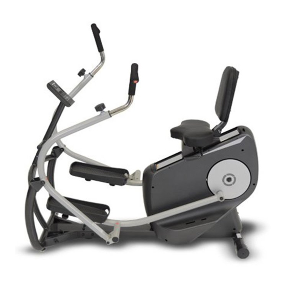
- Page 1 CS1 CARDIOSTRIDER USER MANUAL...
-
Page 3: Table Of Contents
WARRANTY……………………………………………..….…………………. 26‐27 BEFORE YOU BEGIN Thank you for selecting the INSPIRE CARDIOSTRIDER. For your safety and benefit, read this manual carefully before using the machine. As a manufacturer, we are committed to providing you complete customer satisfaction. If you have any questions, or find there are missing or damaged parts, please call our TOLL-FREE customer service number. -
Page 4: Important Safety Notice
IMPORTANT SAFETY NOTICE PLEASE READ AND SAVE THESE INSTRUCTIONS PRECAUTIONS This exercise machine is built for optimum safety. However, certain precautions apply whenever you operate a piece of exercise equipment. Be sure to read the entire manual before you assemble or operate your machine. -
Page 5: Warning Label Placement
WARNING LABEL PLACEMENT The warning labels have been placed on the unit in location shown. If the labels are missing or illegible, please call customer service at 1-877-738-1729 for replacements. Apply the labels in location shown. -
Page 6: Contents Of Packaging
CONTENTS OF PACKAGING... -
Page 7: Hardware Pack
CARDIOSTRIDER HARDWARE PACK NOTE: The following parts are not drawn to scale. Please use your own ruler or scale to measure the size. -
Page 8: Assembly Instructions
CARDIOSTRIDER ASSEMBLY INSTRUCTION STEP 1 (see figure 1) a) Remove contents of packaging leaving only the large styrofoam block supporting the rear part of the unit. The center tube should protrude freely at the front as shown below. b) Slide Front Frame Assembly (#43) up to Main Frame Assembly (#25). Assemble computer connectors (#40 and #41). - Page 9 ...
- Page 10 STEP 2 a) Assemble Backrest Assembly (#7) onto Seat Slider Assembly with qty 1 – M8x70 bolt (#9), qty 1 – M8 washer (#3), and qty 1 – Locking Cap Nut (#2). b) Choose a preferred Seatback Recline Angle (See Figure B). The Backrest Assembly (#7) may be installed in 3 different recline angles (FORWARD, MIDDLE, BACK) based on the user’s preferred position.
- Page 12 STEP 3 a) Assemble Right Pedal (#31) onto Right Pedal Arm Assembly (#24) using qty 2 – M6 Molded Plastic Nuts (#36) and qty 2 – 4.2x6 self tapping screws (#37). b) Assemble Right Pedal Arm Assembly (#24) onto the Right Side Crank. NOTE: THERE IS A SPACER INSIDE THIS PEDAL ARM PIVOT.
- Page 14 STEP 4 a) Place Swing Arm Assembly (#21) onto the right side U-Bracket of the Front Frame Assembly (#43). Secure using qty 1 – Ø10x75mm Shoulder Bolt (#39), qty 1 – M8 Washer (#3), and qty 1 – M8 Locking Cap Nut (#2). b) Assemble Swing Arm Assembly (#21) to Right Pedal Arm Assembly (#24) using qty 1 –...
- Page 16 STEP 5 a) Place Right Handle Assembly (#11) onto Swing Arm Assembly (#21). Choose preferred handle location and secure using Pop Pin (#29). b) Place Left Handle Assembly (#20) onto Swing Arm Assembly (#21). Choose preferred handle location and secure using Pop Pin (#29).
- Page 17 STEP 6 a) Connect Computer Console connector (b) to Upper Mast Cable (#34) and secure the Computer Console (#26) to the Console Mast (#33) using qty 4 – M4 screws (#35). b) Connect Upper Mast Cable (#41) to Main Console Cable (#34) and attach Console Mast (#33) to Front Frame Assembly (#43) using qty 3 –...
- Page 18 STEP 7: CONNECTION OF CHILD SAFETY LOCK a) IMPORTANT FINAL STEP: Screw threaded nut of CHILD SAFETY LOCK ASSEMBLY (#42) onto the exposed bolt threads of the FRONT FRAME ASSEMBLY (#43). (see FIGURE A below) ENGAGING THE CHILD SAFETY LOCK ASSEMBLY 1.
-
Page 19: Computer Operation Guideline
COMPUTER OPERATION DISPLAY A. TIME: During a workout the time counts up from 0:00. TIME may also be set as a goal and will count down from a set time. B. DISTANCE: Keeps track of total DISTANCE traveled during a workout (miles) C. - Page 20 GOAL PROGRAMS The CS1 computer console may also run a goal program in which the user reaches a Total Calorie, Total Distance, or Total Time before the workout is complete. 1. When computer is in STOP mode, press the ENTER button to toggle between TIME, DISTANCE, and CALORIES.
-
Page 21: Parts List
PARTS LIST Seq. Part No Part Name Spec Q'TY 1 RC801‐630‐001A Power Adapter 120 VAC 1 2 0110‐808‐008 Cap Nut M8 Black Zinc Plating 5 3 0116‐008‐010 Flat Washer φ8 electrophoretic 26 4 0114‐742‐198 Self tapping screw ST4.2*19 15 5 RC800‐391‐013 Lock pin φ8*63 1 6 0113‐208‐358A Allen head bolt M8*35 Thread length:15 2 7 RC801‐260‐002 Backrest Assembly ... - Page 22 28 RC801‐801‐002 Left pedal 1 29 RC800‐801‐202 Knob M16*1.5 2 30 RC801‐561‐002 Allen head shoulder bolt φ10*82.5mm 2 31 RC801‐801‐003 Right Pedal 1 32 0113‐008‐168 Allen head bolt M8*16mm 11 33 RC801‐210‐001 Console Mast 1 34 RC801‐630‐001B Control cable (Upper) 1 35 0113‐104‐088 Allen Head bolt M4*8mm 8 36 ...
- Page 23 Hex socket pan head 61 0113‐208‐218 M8*20 7 screws Motor, resistance 62 RC801‐630‐001F 1 adjustment 63 RC800‐221‐004 Bearing Cup 3 φ25 1 64 RC801‐220‐002 Belt wheel shaft 1 φ260,J6, 65 0140‐206‐121 Belt 470,J6(FANGSHOU) 1 66 RC801‐630‐001G Console power cord 1 67 RC800‐801‐003 Main cover L 1 68 RC800‐391‐007 Plastic sleeve Φ10*41.5 ...
-
Page 26: Warranty
Warranty This Warranty applies to Inspire Cardio products manufactured or distributed by FG1 LLC. This Product is for retail use only. It is NOT warranted for LIGHT-COMMERCIAL or HEALTH CLUB use. CONSUMER USE: 10 YEAR FRAME: Includes Main Frame and Welds... - Page 27 This is the only express warranty applicable to FG1’s “Inspire” branded strength products. FG1 neither assumes nor authorizes anyone to assume for it any other express warranty.
- Page 29 FG1, LLC. / HEALTH IN MOTION, LLC. 4945 EAST HUNTER AVE. ANAHEIM, CA 92807 CS1.REVA...
Need help?
Do you have a question about the CS1 and is the answer not in the manual?
Questions and answers
Approximately how much does it weigh? I am trying to figure out if I can move it into my SUV to change locations.
When were these machines available