Table of Contents
Advertisement
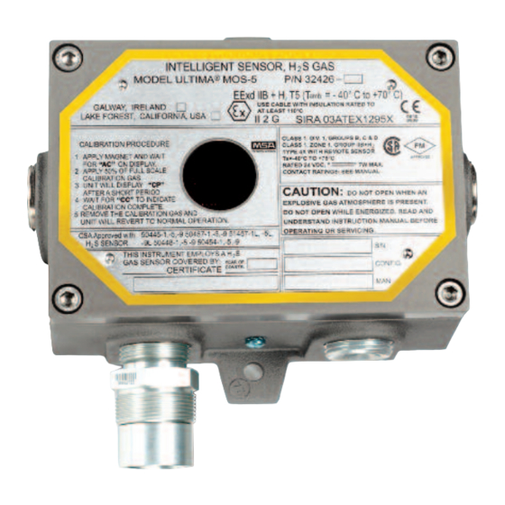
Ultima® MOS-5
Intelligent Sensor for
Hydrogen Sulfide Gas Detection
The information and technical data disclosed in
this document may be used and disseminated
only for the purposes and to the extent
specifically authorized in writing by MSA.
Instruction Manual
MSA reserves the right to change published
specifications and designs without prior notice.
Part No.
Revision
04-14
MANMOS5
MANMOS5
1
Advertisement
Table of Contents

Related Manuals for MSA Ultima MOS-5


Summary of Contents for MSA Ultima MOS-5
- Page 1 MSA. Instruction Manual 04-14 MSA reserves the right to change published specifications and designs without prior notice. MANMOS5 Part No. MANMOS5...
- Page 2 Ultima MOS-5 Detector This page intentionally left blank...
-
Page 3: Table Of Contents
4.0 OPERATION ......................... 17 Start-Up Checklist ........................17 Start-Up ............................ 17 Relay Reset ..........................17 User Selectable Options ......................18 4.4.1 Ultima MOS-5 Intelligent Sensor User Menu Structure ..........19 4.4.2 Sensor Range ......................19 4.4.3 Calibration Output ....................... 20 4.4.4 Warning Relay Settings .................... - Page 4 Exception Responses and Exception Codes ................36 8.6.1 Exception Response ....................36 8.6.2 Exception Code ......................37 Ultima MOS-5 Intelligent Sensor Command Register Locations ..........38 Ultima MOS-5 Intelligent Sensor Command Register Details ..........41 8.8.1 Analog (00H) ....................... 41 8.8.2 Mode (01H) .........................
- Page 5 Ultima MOS-5 Detector 8.8.4 Not Used (03H) ......................42 8.8.5 Unit Type (04H) ......................42 8.8.6 Software Revision (05H) ..................... 42 8.8.7 Status Block (06H) ...................... 42 8.8.8 Analog Value (06H) ..................... 42 8.8.9 Mode & Error (07H) ..................... 42 8.8.10 Error Sensor &...
- Page 6 Sensors ........................57 9.5.2 Sensor Housing ......................58 9.5.3 Sensor Accessories ....................58 9.5.4 Calibration Equipment ....................58 9.5.5 Intelligent Sensor (Ultima MOS-5 Intelligent Sensor) Replacement Parts ....59 9.5.6 Recommended Spare Parts for One Year ..............59 FM Approval ..........................60...
-
Page 7: Table Of Figures
Ultima MOS-5 Detector Table of Figures Figure 1: Ultima MOS-5 Intelligent Sensor Outline and Mounting Dimensions, in inches ........1 Figure 2: Spring Type Terminal Block Operation ....................2 Figure 3: Screw Type Terminal Block Operation ....................2 Figure 4: Ultima MOS-5 Intelligent Sensor ......................7 Figure 5: Ultima MOS-5 Intelligent Sensor Outline and Mounting Dimensions, in inches ........ - Page 8 Table 2: Alarm Relay Connections ........................14 Table 3: Warn Relay Connections ........................14 Table 4: Fault Relay Connections ........................14 Table 5: MSA Contact Information ........................32 Table 6: Data Format ............................33 Table 7: Exception Codes ............................ 37 Table 8: Command Register Locations ........................
-
Page 9: Quick Start Guide
• Adjustable wrench for conduit or cable gland connections (not included). The outline and mounting dimensions for the Ultima MOS-5 Intelligent Sensor (Figure 1) should be used when making installation determinations. Information on Class I Division 1 and Zone 1 wiring methods can be found in the NEC and CEC. -
Page 10: Figure 2: Spring Type Terminal Block Operation
12 AWG to 18 AWG stranded or solid wire. Each wire should be stripped before wiring the Ultima MOS-5 Intelligent Sensor. To connect wiring to the spring type terminal block, insert a screwdriver into the orange tab and press down (Figure 2), opening the terminal. - Page 11 Ultima MOS-5 Detector MSA recommends that the Ultima MOS-5 Intelligent Sensor be calibrated 1 hour after start-up and that the calibration be checked at least every 90 days to ensure system integrity. The instrument is now ready to operate. Please consult the manual for more information on the instrument’s many features.
-
Page 12: Introduction
SERVICE. OUVRIR LE CIRCUIT AVANT D'ENLEVER LE COUVERCLE. SPECIAL CONDITIONS OF SAFE USE PERTAINING TO ATEX/IECEx INSTALLATIONS: The Ultima MOS-5 shall not be used as a Safety Related Device as defined by ATEX Directive 94/9/EC, When alternative detector elements are utilized, they shall only be mounted remotely in a suitable certified enclosure in accordance with requirements of their respective certificates and relevant local requirements. -
Page 13: System Integrity Verification
EN 60079-7 and European Directive 94/9/EC. 1.3 System Integrity Verification To ensure operation at optimum performance, MSA recommends that certain maintenance items be performed. Commissioning Safety Systems Before power-up, verify wiring, terminal connections and stability of mounting for all integral safety equipment including the following items: •... - Page 14 Ultima MOS-5 Detector When testing produces results outside of the manufacturer’s specifications, re-calibration or repair and replacement of the suspect device(s) should be performed as necessary. Calibration intervals should be independently established through a documented procedure, including a calibration log, maintained by plant personnel or third party testing services.
-
Page 15: Product Description
“warning” condition. Analog signal (4-20 mA) and relays provide remote and/or discrete indications of the sensor’s operation. Optional dual redundant Modbus, HART, or HART and single Modbus provide digital communication. The Ultima MOS-5 Intelligent Sensor is rated explosion-proof for use in the following hazardous areas: •... -
Page 16: Installation
Shipping container contents should be carefully removed and checked against the packing list. If any damage has occurred or there is any discrepancy in the order, please notify MSA as soon as possible. All correspondence with MSA must specify the equipment part number and serial number. -
Page 17: Remote Mounting Of The Sensor From The Electronics
The presence of contaminants in an area does not necessarily preclude the use of an Ultima MOS-5 Intelligent Sensor. The feasibility of using a sensor in such areas must be determined by an analysis of the specific factors in each application, and MSA should be consulted before attempting any such installation. -
Page 18: Mounting And Wiring
Ultima MOS-5 Detector 3.4 Mounting and Wiring WARNING: Unused cable entry holes must be sealed with an approved explosion-proof plug. Red caps supplied by MSA are for dust protection only and must not be left on the unit when installed. WARNING: Conduits must be sealed within 18 inches of the enclosure. -
Page 19: Terminal Connections
Ultima MOS-5 Detector NOTE: The Ultima MOS-5 Intelligent Sensor full 2-year warranty will be voided if customer personnel or third parties damage the Ultima MOS-5 Intelligent Sensor during repair attempts. Sensor heads exposed to the elements may require the accessory mounting threads to be lubricated. -
Page 20: Terminal Block Tb2 - Power And Signal Connections
12 AWG to 18 AWG stranded or solid wire. Each wire should be stripped before wiring the Ultima MOS-5 Intelligent Sensor. To connect wiring to the spring type terminal block, insert a screwdriver into the orange tab and press down (Figure 7). Insert the wire into the terminal and release the orange tab, clamping the wire in the terminal. -
Page 21: Dc Power And Ground Connections
This signal can be sent to an industrial analog to digital converter, or logic solver. The 4 to 20 mA signal provides for control room or other locations remote to the Ultima MOS-5 Intelligent Sensor to display indications of operation and alarm conditions. -
Page 22: Terminal Block Tb3 - Relay Connections
Ultima MOS-5 Detector If a readout device is being used, the DC ground, COM of both systems must be connected together. The analog output can also be configured as a HART communication link. 3.5.5 Terminal Block TB3 – Relay Connections TB3 contains the connections for the relay contacts (optional). -
Page 23: European Union (Eu) Approved Applications
Equipment damaged in this manner is not covered under warranty. 3.6 Maintaining the X/P Integrity Some of the factors that influence the explosion-proof integrity of the Ultima MOS-5 Intelligent Sensor housing are: • Strength of the enclosure material •... - Page 24 Ultima MOS-5 Detector Anytime the cover of the Ultima MOS-5 Intelligent Sensor housing is removed or the cover bolts are loosened, the flame path between the lid and the housing is affected. If power is to be left on while removing the cover or loosening the cover bolts on the Ultima MOS-5 Intelligent Sensor, the area must be declassified.
-
Page 25: Operation
This can be accomplished by three different methods: • The relays can be reset by using a magnet. To do this, place the magnet over the MSA logo on the cover of the unit. After 3 seconds, the display shows “rSt”. After the LED... -
Page 26: User Selectable Options
Latching relays can only be reset if the gas concentration has fallen below the respective relay set point. 4.4 User Selectable Options The Ultima MOS-5 Intelligent Sensor includes many selectable options to provide the user with the most flexible H S gas detector possible. These options include selectable sensor range, warn and alarm relay set points and configuration, HART communications and Modbus communications settings. -
Page 27: Ultima Mos-5 Intelligent Sensor User Menu Structure
To adjust the sensor range of the Ultima MOS-5 Intelligent Sensor, apply the magnet to the MSA logo on the cover of the unit until “SE” is displayed, then remove the magnet. This puts the unit into setup mode. After a few seconds “Sr” will be displayed. Apply and remove the magnet to adjust the sensor range. -
Page 28: Calibration Output
When “Fi” is displayed again, apply and remove the magnet to return to normal operation. 4.4.4 Warning Relay Settings To adjust the warning relay settings of the Ultima MOS-5 Intelligent Sensor, apply the magnet to the MSA logo on the cover of the unit until “SE” is displayed, then remove the magnet. This... -
Page 29: Alarm Relay Settings
To adjust the alarm relay settings of the Ultima MOS-5 Intelligent Sensor, apply the magnet to the MSA logo on the cover of the unit until “SE” is displayed, then remove the magnet. This puts the unit into setup mode. After a few seconds “Hi” will be displayed. Apply and remove the magnet, to change the alarm or “high”... -
Page 30: Modbus Channel 2 Settings
2 make sure HART is disabled. To change the Modbus channel 2 settings, apply the magnet to the MSA logo and set the unit in set up mode. Once “CH2” is displayed, follow the same steps as in section 4.4.5 above. -
Page 31: Gas Check Mode
4.6.1 Procedure for Checking the Calibration Place the magnet over the MSA logo on the cover of the Ultima MOS-5 Intelligent Sensor. Remove the magnet when a flashing pair of bars, “- -” appears on the display (about 10 seconds) (Figure 13). -
Page 32: Calibration
MOS-5 Intelligent Sensor. Please see section 9.3.3 for more information on the analog output values. To enter Calibration Mode, place the magnet over the MSA logo on the cover of the unit (Figure 4) and hold it there until “AC” (Figure 14) appears on the display (about 10 seconds). The display will flash the remaining sensor life (Section 4.7.3) for a few seconds. -
Page 33: Aborting Calibration
NOTE: Once gas has been applied, it is not possible to abort a calibration. If the Ultima MOS-5 Intelligent Sensor is placed in the Calibration Mode and no gas is applied for 12 minutes, the unit reverts to a Fault (F2) condition. Re-applying the magnet over the MSA logo returns the unit to operational mode with the previous calibration values unchanged. -
Page 34: Initializing The Remaining Sensor Life
Section 4.7. While the display is flashing the remaining sensor life estimate during zeroing, apply the magnet to the MSA logo on the cover. The flashing number will change to “100”, indicating the sensor has 100% of remaining sensor life. Complete the calibration per Section 4.7.1. -
Page 35: Figure 18: Portable Purge Calibrator
Place the gas cup over the sensor and initiate the calibration sequence, by placing the magnet over the MSA logo on the cover of the unit. When the letters “AC” appear in the display window, remove the magnet and apply the calibration gas (50% of full-scale) by opening the valve on the cylinder. -
Page 36: Maintenance
MSA (P/N 610-010). 5.2 Storage The Ultima MOS-5 Intelligent Sensor should be stored in a clean, dry area and within the temperature and humidity ranges quoted in the Appendix under Environmental Specifications. Insert red dust caps into any vacant cable entry holes. See section 9.3.4. -
Page 37: Troubleshooting
The output signal informs a remote display module that the Ultima MOS-5 Intelligent Sensor is in the Fault Mode. The display indicates a fault code that can be viewed at the sensor site. Refer to section 9.3.3 for more information on analog output values. -
Page 38: F5 - Sensor Heater Shorted Error
This fault occurs if the supply voltage at the Ultima MOS-5 Intelligent Sensor drops below +18.5 VDC. ACTION - Ensure that the supply voltage is at least +20 VDC at the Ultima MOS-5 Intelligent Sensor. NOTE: With long supply leads, a considerable voltage drop may occur due to the electrical resistance of the leads. -
Page 39: F9 - Gas Check Period Exceeded
6.1.8 F9 - Gas Check Period Exceeded If the Ultima MOS-5 Intelligent Sensor is left in the Gas Check Mode for more than 12 minutes with test gas applied, this fault occurs. ACTION - Place the magnet over the MSA logo on the cover to return the unit to normal operation. -
Page 40: Customer Support
United States MSA Europe Thiemannstrasse 1 Phone: +49 [30] 68 86 0 12059 Berlin Fax: +49 [30] 68 86 15 58 Germany Email: info.de@MSAsafety.com Additional MSA office locations can be found on our website – www.MSAsafety.com Table 5: MSA Contact Information... -
Page 41: Modbus Interface
8.3.1 Modbus Read Query Message Byte Modbus Range Referenced to Ultima MOS-5 Intelligent Sensor Slave Address 1-247* (Decimal) Ultima MOS-5 Intelligent Sensor ID (Address) Function Code Read Holding Registers Starting Address Hi** Not Used by Ultima MOS-5 Intelligent Sensor Starting Address Lo**... - Page 42 8.3.2 Modbus Read Response Message Byte Modbus Range Referenced to Ultima MOS-5 Intelligent Sensor Slave Address 1-247* (Decimal) Ultima MOS-5 Intelligent Sensor ID (Address) Function Code Read Holding Registers Byte Count No. Of Data Bytes Data Hi 00-FF (Hex) Ultima MOS-5 Intelligent Sensor Hi...
-
Page 43: Modbus Read Response Message
Intelligent Sensor Register Address Lo 00-FF (Hex) Ultima MOS-5 Intelligent Sensor Commands Preset Data Hi 00-FF (Hex) Ultima MOS-5 Intelligent Sensor Hi Byte Command Data Preset Data Lo 00-FF (Hex) Ultima MOS-5 Intelligent Sensor Lo Byte Command Data CRC Lo... -
Page 44: Function Codes Supported
• If the Ultima MOS-5 Intelligent Sensor receives the query without a communications error, but cannot process it due to reading or writing to a non-existent Ultima MOS-5 Intelligent Sensor command register, then the Ultima MOS-5 Intelligent Sensor returns an exception response message informing the master of the error. -
Page 45: Exception Code
Ultima MOS-5 Intelligent Sensor returns an exception code in the data field, which describes the Ultima MOS-5 Intelligent Sensor condition that caused the exception. Below is a list of exception codes that are supported by the Ultima MOS-5 Intelligent Sensor: Code... -
Page 46: Ultima Mos-5 Intelligent Sensor Command Register Locations
Ultima MOS-5 Detector 8.7 Ultima MOS-5 Command Register Locations Register Master I/O Parameter Function Type Scale Access Address Address Analog 0-20 mA Current Output Value 16-Bit 0000 40001 Mode Indicates and Controls Mode 0001 40002 Status/Error Indicates Errors 0002 40003... - Page 47 Ultima MOS-5 Detector Register Master I/O Parameter Function Type Scale Access Address Address Not Used 001C 40029 HART EN/DE Enable/Disable 001D 40030 HART Test Transmit a constant 1 or 0 Value 0,1,2 001E 40031 signal Cal Abort Abort calibration 001F...
-
Page 48: Table 8: Command Register Locations
Ultima MOS-5 Detector Register Master I/O Parameter Function Type Scale Access Address Address Bus Activity Rate in % of This Decimal 0071 40114 Activity Rate Addressed Node Other Addressed Nodes Ch2 Function Total # of Function Code Errors Value 16-Bit... -
Page 49: Ultima Mos-5 Intelligent Sensor Command Register Details
16-bit value. The scaling is 0 - 65535 decimal, which corresponds to 0 - 21.7 mA. 8.8.2 Mode (01H) A read returns the present mode of the Ultima MOS-5 Intelligent Sensor. A write command changes the mode to the requested mode. A data value of 08 starts calibration mode if the unit is in the run mode. -
Page 50: Not Used (03H)
8.8.5 Unit Type (04H) A read returns the decimal value 4005. This identifies the Ultima MOS-5 Intelligent Sensor. 8.8.6 Software Revision (05H) A read returns the software revision of the Ultima MOS-5 Intelligent Sensor in 2 ASCII characters. 8.8.7 Status Block (06H) A read returns a 6-byte message containing the analog (2 bytes), mode (1 byte), status/error (2 bytes), and sensor life (1 byte) in that order. -
Page 51: Display (0X09H & 0X0Ah)
8.8.13 Alarm Settings (0DH) A read returns the present alarm settings of the Ultima MOS-5 Intelligent Sensor. A write command changes the settings to the requested values. The set points are programmable in 5% FS steps (1% FS steps for 20 ppm range). -
Page 52: Warn Settings (0Eh)
(7-0) 8.8.14 Warn Settings (0EH) A read returns the present warn settings of the Ultima MOS-5 Intelligent Sensor. A write command changes the settings to the requested values. The set points are programmable in 5% FS steps (1% FS steps for 20 ppm range). -
Page 53: Com1 Data Format (11H)
Ultima MOS-5 Detector Baud Rate Value Access 2400 Read/Write 4800 Read/Write 9600 Read/Write 19200 Read/Write Table 9: Com1 Baud Rate Exception: If the baud rate is not in range, an illegal data value (03) is returned. 8.8.17 Com1 Data Format (11H) A read command returns the current data format for Com1. -
Page 54: Not Used (15H)
Ultima MOS-5 Detector Data Parity Stop Format Data(Bits 9-8) Access None 8-N-1 Read/Write Even 8-E-1 Read/Write 8-O-1 Read/Write None 8-N-2 Read/Write Table 12: Com2 Data Format Exception: If the data format is not in range an illegal data value (03) is returned. -
Page 55: Abort Calibration (1Fh)
Ultima MOS-5 Detector Code Results Normal Constant ones Constant zeros 8.9.2 Abort Calibration (1Fh) Sending a “1” causes a calibration or calibration abort. 8.9.3 Total Receive Errors (20H) A read indicates the total number of Modbus communication receive errors that occurred in the slave device. -
Page 56: Overrun Errors (28H)
Normally in HART mode the low current does not decrease below 3.5 mA. If use of current levels below 3.5mA is required by an application, the Ultima MOS-5 Intelligent Sensor features and expanded scale that permits faults to be set as low as 1.25 mA. A read returns “1”... - Page 57 If the unit fails to zero or calibrate, the event is not recorded. If the calibration is aborted the event is also not recorded. Note the zero and calibration are one operation in the Ultima MOS-5 Intelligent Sensor. There are a total of ten event time stamps stored.
- Page 58 Ultima MOS-5 Detector Address Parameter Function Data Type Data range Access (hex) Structure time Hi Hi byte – year, low byte Numeric value 0 – 65535 Warn – month for warning Structure time Hi byte – day, low byte Numeric value 0 –...
-
Page 59: User Information (60H To 6Fh)
Ultima MOS-5 Detector Address Parameter Function Data Type Data range Access (hex) Maintenance Seconds Time Hi for Numeric value 0 – 65535 Maintenance Seconds Time Hi lamp test event log entries Seconds Time Low for Seconds Time lamp test event log Numeric value 0 –... -
Page 60: Ch2 Total Receive Errors (70H)
Ultima MOS-5 Detector 8.9.17 CH2 Total Receive Errors (70H) A read indicates the total Modbus communication hardware receive errors that occurred in the slave device. The maximum count is 65535 and then the counter will rollover to zero and begin counting again. -
Page 61: Ch2 Framing Errors (79H)
Ultima MOS-5 Detector 8.9.26 CH2 Framing Errors (79H) A read indicates the number of hardware UART framing errors that occurred in the slave device. The maximum count is 65535 and then the counter will rollover to zero and begin counting again. -
Page 62: Appendix
9.0 Appendix 9.1 Warranty MSA warrants the Ultima MOS-5 Intelligent Sensor to be free from defects in workmanship or material under normal use and service within two years from the date of shipment. MSA will repair or replace without charge any such equipment found to be defective during the warranty period. -
Page 63: Specifications
Ultima MOS-5 Detector 9.3 Specifications 9.3.1 System Specifications Sensor Type: Continuous diffusion, adsorption type metal oxide semiconductor (MOS) Sensor Life: 3 to 5 years typical Repeatability: +2 ppm or 10% of the applied gas, whichever is greater Long Term Drift: ±2 ppm or 10% of reading, whichever value provides the wider... -
Page 64: Table 14: 24 Vdc Cable Lengths
HART: RX 100K CX 5nF Cable Requirements: 3-wire shielded cable. Maximum distance between Ultima MOS-5 Intelligent Sensor and power source @ 24 VDC nominal with warn & alarm relay energized. If no relays are used the distance can be increased by 20%. -
Page 65: Environmental Specifications
• Listed in Emerson Process Management’s Aware device list. 9.5 Spare Parts and Accessories To order spare parts and/or accessories, please contact the nearest MSA Representative or, MSA directly, and give the following information: • Part Number of Spare Part or Accessory •... -
Page 66: Sensor Housing
Ultima MOS-5 Detector 51457-5L 0 to 50 ppm, Stainless Steel, Sintered Steel Arrestor 51457-9L 0 to 20 ppm, Stainless Steel, Sintered Steel Arrestor 9.5.2 Sensor Housing 10252-1 Universal Housing 9.5.3 Sensor Accessories 10041-1 Duct Mounting Plate 10044-1 Dust Guard Kit - 1 Guard, 12 Replaceable Screens... -
Page 67: Intelligent Sensor (Ultima Mos-5 Intelligent Sensor) Replacement Parts
922-016 Replacement Regulator (0.2 L/min) Replacement Hose 960-345 Hose Clamp, 5/16” 960-346 Hose Clamp, ¼” 1400152-1 Calibration Cup 9.5.5 Intelligent Sensor (Ultima MOS-5 Intelligent Sensor) Replacement Parts 32471-1,-2,-3,-4 Control Board Electronics 32451-1,-2 Output Board Electronics 32441-1 Display Board Electronics 32424-2... -
Page 68: Fm Approval
In order to maintain FMRC approved system, the control instrument, to which the subject instrument is connected, must also be FMRC approved. The following sensors have been FMRC approved for use with the Ultima MOS-5 Intelligent Sensor: •...
Need help?
Do you have a question about the Ultima MOS-5 and is the answer not in the manual?
Questions and answers