Table of Contents
Advertisement
Quick Links
Model S4000TH
Intelligent Sensor for
Hydrogen Sulfide Gas Detection
The information and technical data disclosed in
this document may be used and disseminated
only for the purposes and to the extent
specifically authorized in writing by General
Monitors.
Instruction Manual
General Monitors reserves the right to change
published specifications and designs without
prior notice.
Part No.
Revision
10-16
MANS4000TH
MANS4000TH
N/10-16
Advertisement
Table of Contents

Subscribe to Our Youtube Channel
Related Manuals for MSA General Monitors S4000TH


Summary of Contents for MSA General Monitors S4000TH
- Page 1 Model S4000TH Intelligent Sensor for Hydrogen Sulfide Gas Detection The information and technical data disclosed in this document may be used and disseminated only for the purposes and to the extent specifically authorized in writing by General Monitors. Instruction Manual 10-16 General Monitors reserves the right to change published specifications and designs without...
- Page 2 Model S4000TH This page intentionally left blank...
-
Page 3: Table Of Contents
Model S4000TH Table of Contents MODEL S4000TH .......................... I INTELLIGENT SENSOR FOR ....................... I HYDROGEN SULFIDE GAS DETECTION ................... I TABLE OF FIGURES ........................VI TABLE OF TABLES ........................VII QUICK START GUIDE ......................... 1 Mounting and Wiring ..........................1 ... -
Page 4: Model S4000Th
Model S4000TH 4.4.3 Calibration Output ....................... 22 4.4.4 Warning Relay Settings ....................22 4.4.5 Alarm Relay Settings....................23 4.4.6 Modbus Channel 1 Settings ..................23 4.4.7 Modbus Channel 2 Settings ..................24 ... - Page 5 Model S4000TH S4000TH Command Register Locations ................. 38 S4000TH Command Register Details ..................40 8.8.1 Analog (00H) ....................... 40 8.8.2 Mode (01H) ......................... 40 8.8.3 Status/Error (02H) ....................... 41 ...
- Page 6 Model S4000TH 8.9.25 CH2 Overrun Errors (78H) ..................52 8.9.26 CH2 Framing Errors (79H) ..................52 8.9.27 CH2 Total Software CH1 Errors (7AH) ............... 52 8.9.28 Not Used (7BH) ......................53 ...
-
Page 7: Table Of Figures
Model S4000TH Table of Figures Figure 1: S4000TH Outline and Mounting Dimensions, in inches ................1 Figure 2: S4000TH with RGC Outline and Mounting Dimensions, in inches ............2 Figure 3: Spring Type Terminal Block Operation ....................2 ... - Page 8 Model S4000TH Table of Tables Table 1: TB2 Power and Signal Connections ....................... 14 Table 2: Ground or Common Connections ......................15 Table 3: Power Connections ..........................15 Table 4: Analog Signal Connections ........................16 Table 5: Alarm Relay Connections ........................
-
Page 9: Quick Start Guide
Model S4000TH Quick Start Guide Mounting and Wiring Tools Required “5mm” Allen head wrench to remove enclosure lid (included with gas detector). Flat-head screwdriver maximum 3/16 in (5 mm) width for terminal block connections (included with gas detector). ... -
Page 10: Terminal Connections
Model S4000TH Figure 2: S4000TH with RGC Outline and Mounting Dimensions, in inches Terminal Connections The terminal blocks (TB) are located inside the housing and can be accessed by removing the cover. A label inside of the housing cover provides a diagram of all the terminal connections. It is recommended that a minimum three-wire shielded cable be used for making the power and 0-20mA Output connection on TB2 of the S4000TH. -
Page 11: Figure 4: Screw Type Terminal Block Operation
Model S4000TH To connect wiring to the screw type terminal block, loosen the top screw counter clock wise (Figure 4). Insert the wire into the terminal and tighten the top screw clockwise. Figure 4: Screw Type Terminal Block Operation NOTE: Power must remain disconnected until all other wiring connections have been made. The maximum distance between the S4000TH and the power supply is 2,000 feet or 610 meters (each cable run should be as short as possible). -
Page 12: Introduction
Model S4000TH 1.0 Introduction 1.1 Protection for Life General Monitors’ mission is to benefit society by providing solutions through industry leading safety products, services, and systems that save lives and protect capital resources from the dangers of hazardous flames, gases, and vapors. This manual provides instruction for installing and operating General Monitors’... -
Page 13: System Integrity Verification
Model S4000TH Cement Ambient Range Enclosure Type 2850FT Cat 11 -40°C to +70°C Enclosures that are certified by a notified body and or 2762 Cat 17 satisfy the requirements of the current edition of EN 60079-1 or EN 60079-7 and European Directive 94/9/EC. - Page 14 Model S4000TH Periodic Testing/Calibration of Field Devices Periodic testing/calibrating should be performed per the manufacturer’s recommendations and instructions. Testing/Calibrating procedures should include, verify integrity of all optical surfaces and devices When testing produces results outside of the manufacturer’s specifications, re-calibration or repair and replacement of the suspect device(s) should be performed as necessary.
-
Page 15: Product Description
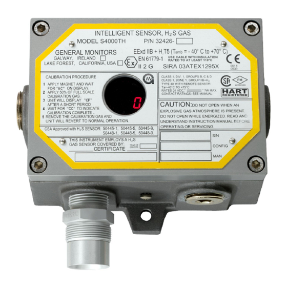
Model S4000TH 2.0 Product Description 2.1 General Description The Model S4000TH is an intelligent sensor for the detection of hydrogen sulfide (H S) gas. The microprocessor-based electronics process information at the sensor site within an explosion-proof housing. A digital display provides indications and display codes that can be viewed through a window in the cover. -
Page 16: Installation
Model S4000TH Figure 6: Model S4000TH Intelligent Sensor with RGC NOTE: The image in Figure 6 is for reference only. See section 9.3 for actual product specifications. 3.0 Installation 3.1 Receipt of Equipment All equipment shipped by General Monitors is pre-packed in shock absorbing containers, which provide protection against physical damage (original containers should be kept for future shipping or storage needs). -
Page 17: Tools Required
Model S4000TH All correspondence with General Monitors must specify the equipment part number and serial number. Although the factory tests each unit, a complete system checkout is suggested upon initial installation to ensure system integrity. WARNING: Only suitably skilled and competent personnel should carry out installation and maintenance. -
Page 18: Remote Mounting Of The Sensor From The Electronics
Model S4000TH Heavy metals, e.g. tetraethyl lead Caustic and Acidic liquids and vapors Glycol The presence of contaminants in an area does not necessarily preclude the use of a S4000TH Intelligent Sensor. The feasibility of using a sensor in such areas must be determined by an analysis of the specific factors in each application, and General Monitors should be consulted before attempting any such installation. -
Page 19: Mounting And Wiring
Model S4000TH 3.4 Mounting and Wiring WARNING: Unused cable entry holes must be sealed with a suitably certified ATEX or IECEx approved explosion-proof plug. Red caps supplied by General Monitors are for dust protection only and must not be left on the unit when installed. WARNING: Conduits must be sealed within 18 inches of the enclosure. -
Page 20: Figure 8: S4000Th With Rgc Outline And Mounting Dimensions, In Inches
Model S4000TH Figure 8: S4000TH with RGC Outline and Mounting Dimensions, in inches WARNING: Acetic acid will cause damage to metal components, metal hardware, ceramic IC’s and other parts. If damage results from the use of a sealant that outgases acetic acid (RTV silicone), the warranty will be void. -
Page 21: Terminal Connections
Model S4000TH 3.5 Terminal Connections The terminal blocks (TB) are located inside the housing and can be accessed by removing the cover. A label on the inside of the housing cover provides details of all the terminal connections. Figure 9: S4000TH Terminal Block Locations 3.5.1 Terminal Block TB1 –... -
Page 22: Figure 10: Spring Type Terminal Block Operation
Model S4000TH CH2 Modbus - CH2 Modbus + Remote Calibration Relay Reset Ground +24 VDC Power Table 1: TB2 Power and Signal Connections It is recommended that a minimum three-wire shielded cable be used for making the power and 0-20mA Output connection on the S4000TH. It is also recommended that separate two-wire shielded twisted pair cables be used for making the Modbus connections. -
Page 23: Dc Power And Ground Connections
Model S4000TH NOTE: Up to 12 AWG wire can be used if it is carefully striped. This applies only to a screw type terminal connection (Figure 8). 3.5.3 DC Power and Ground Connections The customer must provide primary DC power, unless one of the following General Monitors’ Modules is being used with the S4000TH: ... -
Page 24: Analog Signal Connections
Model S4000TH 3.5.4 Analog Signal Connections The S4000TH Intelligent Transmitter provides a 4 to 20 mA output signal. This signal can be sent to a General Monitors readout and relay display module, an industrial analog to digital converter, or logic solver. The 4 to 20 mA signal provides for control room or other locations remote to the S4000TH to display indications of operation and alarm conditions. -
Page 25: European Union (Eu) Approved Applications
Model S4000TH NOTE: Fault relay is normally energized. Relay will change state after power up. WARNING: Contact with PCB components should be avoided to prevent damage by static electricity. All wire connections are made to the Terminal Blocks. WARNING: Relay contacts must be protected against transient and over voltage conditions (Figure 13). -
Page 26: Maintaining The X/P Integrity
Model S4000TH WARNING: Under NO circumstances should equipment be connected or disconnected when under power. This is contrary to hazardous area regulations and may lead to serious damage to the equipment. Equipment damaged in this manner is not covered under warranty. 3.6 Maintaining the X/P Integrity Some of the factors that influence the explosion-proof integrity of the S4000TH housing are: ... -
Page 27: Operation
Model S4000TH 4.0 Operation 4.1 Start-Up Checklist Prior to starting the system, verify the following: Inhibit any external devices, such as trip amplifiers, PLC, or DCS systems. Verify that the optional settings are set for the desired configuration. ... -
Page 28: User Selectable Options
Model S4000TH Figure 14: Relay Reset The relays can be reset via the remote reset input terminals on TB2. Connect a normally open switch between terminal TB2-7 and TB2-8. Closing the switch momentarily will reset the relays. General Monitors’ explosion-proof switch, P/N 30051- 1 can be used for this purpose. -
Page 29: Model S4000Th User Menu Structure
Model S4000TH 4.4.1 Model S4000TH User Menu Structure Operate “rSt” “AC” “SE” “SE” Time Out “- -” Fault Set Sensor Range “Sr” Reset Enter Calibration “Fi” 20,50,100 ppm Enter Gas Check Mode Mode Relays If Hart Enabled Reset Sensor Detected? Life? “Fi”... -
Page 30: Calibration Output
Model S4000TH magnet, to return to the next level of the setup menu. When “Fi” is displayed again, apply and remove the magnet, the unit will go to calibration mode. The display will flash the remaining sensor life for a few seconds. Ensure that the sensor is seeing clean air during this time. Apply the calibration gas concentration to the sensor (50% FS of the desired range of H S. -
Page 31: Alarm Relay Settings
Model S4000TH First, the energized/de-energized state of the relay is shown by either “En” or “dE” being displayed, respectively. Apply and remove the magnet until the desired state is displayed. After a few seconds the latching/non-latching state of the relay is shown by either “La” or “nL”. Apply and remove the magnet, until the desired state is displayed. -
Page 32: Modbus Channel 2 Settings
Model S4000TH After a few seconds, the current Data Format for Modbus Channel 1 is displayed. If another data format is to be selected, apply and remove the magnet until the desired data format is displayed. The choices are: 8-N-1 “8n1”, 8-N-2 “8n2”, 8-E-1 “8E1”, or 8-O-1 “8O1”. After a few seconds, the current address for Modbus Channel 1 is displayed. -
Page 33: Gas Check Mode
Model S4000TH The S4000TH HART configuration is compatible with the Emerson 375 Field Communicator and AMS Aware. http://www.emersonprocess.com/ http://www.emersonprocess.com/ams/ 4.6 Gas Check Mode The sensor’s response can be checked without activating external alarms by placing the S4000TH in Gas Check Mode. In this mode, the alarm relays are inhibited and the analog output is fixed at 1.5 mA. -
Page 34: Calibration Procedure
Model S4000TH problems, such as mud collecting on the sensor head, sensors accidentally being painted over, etc. General Monitors recommends that a calibration schedule be established and followed. A logbook should also be kept, showing calibration dates and dates of sensor replacement. 4.7.1 Calibration Procedure If hydrogen sulfide (H S) gas is suspected to be present, it will be necessary to purge the... -
Page 35: Aborting Calibration
Model S4000TH The unit is now calibrated and the new span value has been stored in the non-volatile memory (EEPROM). NOTE: The sensor life figure displayed is that calculated on completion of the last calibration. To determine the current sensor life, calibrate unit and then repeat steps 1 and 2. 4.7.2 Aborting Calibration If calibration is to be aborted and gas has not been applied, wait ninety seconds and reapply the magnet. -
Page 36: Calibrating With An H
Model S4000TH 50% FS of H S of the sensor range. Follow the calibration procedure in Section 4.7. When the display indicates “AC”, break the ampoule by turning the thumbscrew on the side of the breaker bottle clockwise. The display will change to “CP” indicating that the sensor is seeing the gas. When the display reads “CC”, the calibration is complete. -
Page 37: Calibrating With An Rgc
Model S4000TH Place the gas cup over the sensor and initiate the calibration sequence, by placing the magnet over the GM logo on the cover of the unit. When the letters “AC” appear in the display window, remove the magnet and apply the calibration gas (50% of full-scale) by opening the valve on the cylinder. -
Page 38: Maintenance
Model S4000TH 5.0 Maintenance 5.1 General Maintenance WARNING: Disconnect or inhibit external devices such as trip amplifiers, PLC’s, or DCS systems before performing any maintenance. European Union (EU) Approved Applications: The following grease compound is recommended for use: PBC Polybutylcuprysil, (or equivalent), which has BASEEFA Health & Safety Executive Component Approval No. -
Page 39: Troubleshooting
Model S4000TH 6.0 Troubleshooting CAUTION: Component level repair must be undertaken either by General Monitors’ personnel, or by competent authorized service engineers. SMT PCB repair shall only be performed at a General Monitors’ facility. Failure to comply with this requirement will invalidate the warranty. -
Page 40: F5 - Sensor Heater Shorted Error
Model S4000TH If this does not solve the problem the internal sensor amplifier has a defective part. The unit must be returned for service. 6.1.4 F5 - Sensor Heater Shorted Error This fault indicates that one of the sensor circuit leads is short-circuited to ground or +24 V ACTION - Check the integrity of all sensor connections and ensure that the cable from the S4000TH to the remote sensor is not damaged. -
Page 41: F9 - Gas Check Period Exceeded
Model S4000TH ACTION - Exit setup mode. Enter setup mode again to change any user selectable options, if necessary. 6.1.8 F9 - Gas Check Period Exceeded If the S4000TH is left in the Gas Check Mode for more than 12 minutes with test gas applied, this fault occurs. -
Page 42: Customer Support
Model S4000TH 7.0 Customer Support 7.1 General Monitors’ Offices Area Phone/Email UNITED STATES 26776 Simpatica Circle Phone: +1-949-581-4464. 800-446-4872 Lake Forest, CA 92630 Email: info.gm@MSAsafety.com IRELAND Ballybrit Business Park Galway Republic of Ireland, H91 H6P2 Phone: +353-91-751175 SINGAPORE No. 2 Kallang Pudding Rd. #09-16 Mactech Building Singapore 349307 Phone: +65-6-748-3488... -
Page 43: Modbus Interface
Model S4000TH 8.0 Modbus Interface 8.1 Baud Rate The baud rate is selectable via the Modbus Communications Interface. The selectable baud rates are 19200, 9600, 4800, or 2400 bits per second. 8.2 Data Format The Data Format is selectable via the Modbus Communications Interface. The selectable data formats are as follows: Data Bits Parity... -
Page 44: Modbus Write Command Protocol (Query/Response)
Model S4000TH 8.4 Modbus Write Command Protocol (Query/Response) 8.4.1 Modbus Write Query Message Byte Modbus Range Referenced to S4000TH Slave Address 1-247* (Decimal) S4000TH ID (Address) Function Code Preset Single Register Register Address Hi Not Used by S4000TH Register Address Lo 00-FF (Hex) S4000TH Commands Preset Data Hi... -
Page 45: Exception Code
Model S4000TH If the S4000TH receives the query without a communications error, but cannot process the response to the master within the master’s timeout setting, then no response is returned from the S4000TH. The master device eventually processes a timeout condition for the query. -
Page 46: S4000Th Command Register Locations
Model S4000TH 8.7 S4000TH Command Register Locations Register Master I/O Parameter Function Type Scale Access Address Address Analog 0-20 mA Current Output Value 16-Bit 0000 40001 Mode Indicates and Controls Mode 0001 40002 Status/Error Indicates Errors 0002 40003 Not Used 0003 40004 Unit Type... - Page 47 Model S4000TH Register Master I/O Parameter Function Type Scale Access Address Address Not Used 001C 40029 HART EN/DE Enable/Disable 001D 40030 HART Test Transmit a constant 1 or 0 Value 0,1,2 001E 40031 signal Cal Abort Abort calibration 001F 40032 Total Receive Total # of Receive Errors Value...
-
Page 48: S4000Th Command Register Details
Model S4000TH Address Address Ch2 Bus Activity Bus Activity Rate in % of This Decimal 0071 40114 Rate % Addressed Node vs. Other Addressed Nodes Function Total # of Function Code Value 16-Bit 0072 40115 Code Errors Errors Starting Total # of Starting Address Value 16-Bit 0073... -
Page 49: Status/Error (02H)
Model S4000TH Function Bit Position Access Calibration Complete 7 MSB Read Spanning Read Zero Complete, Waiting for Gas Read Zeroing Read Calibration Mode Read/Write Calibration Check Mode Read/Write Run Mode Read Startup Mode 0 LSB Read 8.8.3 Status/Error (02H) A read returns the alarm state and errors that are occurring at the present time, which are indicated, by bit position. -
Page 50: Analog Value (06H)
Model S4000TH 8.8.8 Analog Value (06H) A value which is proportional to the 0-20 mA output current. The current is based on a 16-bit value. The scaling is 0 - 65535 decimal, which corresponds to 0 - 21.7 mA. 8.8.9 Mode & Error (07H) See mode (02) 8000 Calibration Complete... -
Page 51: Serial Number (0Bh/0Ch)
Model S4000TH digit (MID) and the least significant digit (LSD) in ASCII. The upper word represents the MID and the lower word represents the LSD. DP_LSD 0x01 DP_MID 0x02 DP_MSD 0x04 WRN_LED 0x08 ALM_LED 0x10 8.8.12 Serial Number (0BH/0CH) The serial number is a 32-bit word but the value is only 23 bits long. The upper bits are always zero. -
Page 52: Warn Settings (0Eh)
Model S4000TH Byte Function Bit Position Access High Not Used 15 MSB Read Not Used Read Not Used Read Not Used Read Not Used Read Not Used Read Latching/Non-Latching Energized/De-Energized Set point (7-0) 8.8.14 Warn Settings (0EH) A read returns the present warn settings of the S4000TH. A write command changes the settings to the requested values. -
Page 53: Com1 Data Format (11H)
Model S4000TH Baud Rate Value Access 2400 Read/Write 4800 Read/Write 9600 Read/Write 19200 Read/Write Table 12: Com1 Baud Rate Exception: If the baud rate is not in range, an illegal data value (03) is returned. 8.8.17 Com1 Data Format (11H) A read command returns the current data format for Com1. -
Page 54: Not Used (15H)
Model S4000TH Data Parity Stop Format Data(Bits 9-8) Access None 8-N-1 Read/Write Even 8-E-1 Read/Write 8-O-1 Read/Write None 8-N-2 Read/Write Table 15: Com2 Data Format Exception: If the data format is not in range an illegal data value (03) is returned. 8.8.21 Not Used (15H) 8.8.22 Reset Alarms (16H) A write to this register with a data value of 1 resets any latched alarms provided the current... -
Page 55: Abort Calibration (1Fh)
Model S4000TH Code Results Normal Constant ones Constant zeros 8.9.2 Abort Calibration (1Fh) Sending a “1” causes a calibration or calibration abort. 8.9.3 Total Receive Errors (20H) A read indicates the total number of Modbus communication receive errors that occurred in the slave device. -
Page 56: Overrun Errors (28H)
Model S4000TH 8.9.10 Overrun Errors (28H) A read indicates the number of hardware UART overrun errors that occurred in the slave device. When the counter for these errors reaches 65535, it rolls over to zero and begins counting again. 8.9.11 Framing Errors (29H) A read indicates the number of hardware UART framing errors that occurred in the slave device. - Page 57 Model S4000TH The time the gas level reaches the warning level is recorded. Each time this happens a counter is incremented. The end of the event is when the gas goes below 5%.The counter is also saved. There are a total of ten event time stamps stored. Alarm The time where the gas level reaches the alarm level is recorded.
- Page 58 Model S4000TH Structure time Hi byte – day, low byte Numeric value 0 – 65535 Warn – hour warning event log entries Structure time Hi byte – min, low byte Numeric value 0 – 65535 Warn – sec for warning event log entries Reserved Reserved...
-
Page 59: User Information (60H To 6Fh)
Model S4000TH Seconds Time lamp test event log Numeric value 0 – 65535 Maintenance entries Structure time Hi Hi byte – year, low byte Numeric value 0 – 65535 Maintenance – month for lamp test event log entries Structure time Hi byte –... -
Page 60: Ch2 Bus Activity Rate % (71H)
Model S4000TH 8.9.18 CH2 Bus Activity Rate % (71H) A read indicates the bus activity rate in percent of this slave’s addressed node versus other addressed nodes. Range of this value is in hex (0-64), which translates to decimal (0-100%). 8.9.19 CH2 Function Code Errors (72H) A read indicates the number of function code errors that occurred in the slave device. -
Page 61: Not Used (7Bh)
Model S4000TH 8.9.28 Not Used (7BH) 8.9.29 CH2 Clear UART Errors (7CH) 8.9.30 CH2 Clear Stats (7DH) -
Page 62: Appendix
Model S4000TH 9.0 Appendix 9.1 Warranty General Monitors warrants the S4000TH to be free from defects in workmanship or material under normal use and service within two years from the date of shipment. General Monitors will repair or replace without charge any such equipment found to be defective during the warranty period. -
Page 63: Specifications
Model S4000TH 9.3 Specifications 9.3.1 System Specifications Sensor Type: Continuous diffusion, adsorption type metal oxide semiconductor (MOS) Sensor Life: 3 to 5 years typical Repeatability: +2 ppm or 10% of the applied gas, whichever is greater Long Term Drift: ±2 ppm or 10% of reading, whichever value provides the wider tolerance (as defined per ISA-92.0.01) Response Time <... -
Page 64: Environmental Specifications
Model S4000TH Faults Monitored: Calibration error, sensor heater error, low DC supply, EEPROM, EPROM, setup error, gas check time exceeded, switch error, magnet error. EMC Protection: Complies with EN 50270, EN 61000-6-4 HART: RX 100K CX 5nF Cable Requirements: 3-wire shielded cable. Maximum distance between S4000TH and power source @ 24 VDC nominal with warn &... -
Page 65: Approvals
Model S4000TH 9.4 Approvals CE Marking; CSA, FM, ATEX, IECEx and EAC approved. Complies with ANSI/ISA- 92.0.01:1998, performance requirements. SIL 2/3 suitable (use in typical environments has a lower safety rating than in clean environments). HART Registered. HART: Approved by the HART Communication Foundation. ... -
Page 66: Sensor Accessories
Model S4000TH 9.5.3 Sensor Accessories 10041-1 Duct Mounting Plate 9.5.4 Calibration Equipment 50000 Breaker Bottle, Single 50004-3 Individual Ampoules, 10 ppm (12 minimum) 50004-21 Individual Ampoules, 25 ppm (12 minimum) 50004-13 Individual Ampoules, 50 ppm (12 minimum) 50008-9 12 Ampoules at 50 ppm (0-100ppm scale) 50008-16 12 Ampoules at 25 ppm (0-50ppm scale) 50008-10... -
Page 67: Intelligent Sensor (S4000Th) Replacement Parts
Model S4000TH Case for Portable Purge Assembly 922-016 Replacement Regulator (0.2 L/min) Replacement Hose 960-345 Hose Clamp, 5/16” 960-346 Hose Clamp, ¼” 1400152-1 Calibration Cup 9.5.5 Intelligent Sensor (S4000TH) Replacement Parts 32471-1,-2,-3,-4 Control Board Electronics 32451-1,-2 Output Board Electronics 32441-1 Display Board Electronics 32424-2 Enclosure Cover Assembly with Window... -
Page 68: Fm Approval
Model S4000TH 9.6 FM Approval Factory Mutual Research Corporation 1151 Boston-Providence Turnpike Norwood, Massachusetts 02062 Approval of the transmitter does not include or imply approval of apparatus, to which the transmitter may be connected and which processes the electronic signal for the eventual end use. - Page 69 Model S4000TH ADDENDUM Product Disposal Considerations This product may contain hazardous and/or toxic substances. EU Member states shall dispose according to WEEE regulations. For further General Monitors’ product WEEE disposal information please visit: www.MSAsafety.com All other countries or states: please dispose of in accordance with existing federal, state and local environmental control regulations.
Need help?
Do you have a question about the General Monitors S4000TH and is the answer not in the manual?
Questions and answers