Table of Contents
Advertisement
W A T E R
Important: These instructions are for the use of
specially trained personnel, experienced in the
Installation of this equipment and related system
components. Some states require licensing of
installation and service personnel. Unqualified
individuals should not attempt to interpret these
instructions or install this equipment. Read
instructions carefully before unpacking, installing and
operating this heat pump unit.
Inspection: This heat pump has been factory
inspected prior to shipment. However, we
recommend you check the carton before unloading
F = 208-230/60/3
G = 460/60/3
K = 575/60/3
J = 380/50/3
Mammoth is committed to a policy of
continuous.
product improvements, and thus
reserves the right to.change specifications and
design without notice.
S O U R C E
Nomenclature
G - 141 - MHC
Voltage:
Unit Size (Nominal Cooling):
071 = 72,250 Btu/hr. cooling
111 = 111,000 Btu/hr. cooling
141 = 148,000 Btu/hr. cooling
181 = 183,000 Btu/hr cooling
221 = 226,000 Btu/hr cooling
271 = 270,000 Btu/hr cooling
321 = 330,000 Btu/hr cooling
381 = 381,000 Btu/hr cooling
© 1/2003 Mammoth Inc.
H E A T
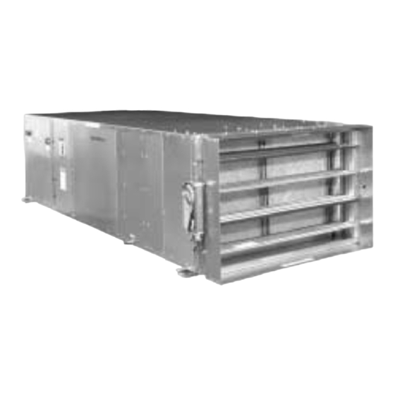
100 Percent Outside Air Units
Sizes 071 thru 381
Installation,
and Maintenance
Instructions
and note any transit damage on all copies of the bill
of lading. Also inspect the unit for concealed shipping
damage after removing packaging. Transit damage
claims must be filed promptly with the freight
company by the purchaser.
Handling: Always handle with care and in the
horizontal position as shipped on the pallet. Moving
the heat pump on its side or dropping it may damage
internal parts.
Location: Unit must be installed indoors in any area
allowing adequate room for mounting of unit and with
access for maintenance and service.
Unit Type:
MHC = 100% Outside Air,
Standard Temperature Range
Design Series "C"
MLC = 100% Outside Air,
Low Temperature Geothermal,
Design Series "C"
(P/N 71144921)
P U M P S
Mammoth Inc.
www.mammoth-inc.com
U-5
Advertisement
Table of Contents

Related Manuals for Mammoth G-141-MHC


Summary of Contents for Mammoth G-141-MHC
- Page 1 221 = 226,000 Btu/hr cooling Design Series “C” 271 = 270,000 Btu/hr cooling 321 = 330,000 Btu/hr cooling 381 = 381,000 Btu/hr cooling Mammoth is committed to a policy of Mammoth Inc. continuous. product improvements, and thus reserves the right to.change specifications and design without notice.
- Page 2 Unit placement – slab-mounted 1. Fit the grommets into the ⁄ -inch diameter holes Mammoth’s 100% outside air heat pump can also be on the mounting rails. Use ⁄ -inch or ⁄ -inch installed on a flat level surface.
- Page 3 2-inch Min. Trap preconditioned or the unit must be shut off. Mammoth offers both optional electric and hot water preheat coils for this situation. See page 5 for Figure 3. Condensate trap detail – side drain additional information on the heaters.
- Page 4 Also available for heat pumps is a condensate Preheat Section hose and two hose clamps. For Mammoth hose kit information as to installation and specifications, see data sheets C-91 and C-93. Electric supply Electrical service and fuses Warning: Turn off electrical power before servicing controls.
- Page 5 (see Figure 4). Hot Water Preheat — Optional Electric Preheat — Optional The Mammoth 100% Outdoor Air unit provides The Mammoth 100% Outdoor Air unit provides optional hot water coils to preheat cold outdoor air to optional electric heat to preheat the outdoor air to a...
- Page 6 Figure 6. 100% outside air unit wiring diagram CIRCUIT #1 COOLING ONLY (FIRST STAGE) WITH HOT GAS REHEAT 208/230 or 460 VOLTS (DEHUMIDIFICATION) 60 HERTZ, 3 PHASE SEE NOTE 2 COMPRESSOR POWER BLOCK SEE NOTES 1, 4 & 5 75 VA TRANSFORMER 24 VAC SEE NOTES...
- Page 7 LEGEND: CIRCUIT #2 Control Voltage Factory Wiring (24 VAC) FIRST STAGE HEATING BLOWER COND STAGE COOLING Control Voltage Field Wiring (24 VAC) MOTOR Line Voltage Factory Wiring Line Voltage Field Wiring COMPRESSOR Ground SEE NOTE 3 Compressor Contactor (Circuit #1) Compressor Contactor (Circuit #2) Blower Contactor Lockout Relay (Circuit #1)
- Page 8 Figure 7. 100% outside air unit with hot water preheat wiring diagram COOL 208/230 or 460 VOLTS 60 HERTZ, 3 PHASE SEE NOTE 2 POWER BLOCK 50 VA TRANSFORMER 24 VAC WHITE DEHUMIDIFICATION YELLOW COMPRESSOR #1 BLUE COMPRESSOR #2 BLUE PINK PINK/BLACK STRIPE PURPLE...
- Page 9 CIRCUIT #2 CIRCUIT #1 1ST STAGE HEATING LING ONLY (FIRST STAGE) LEGEND: 2ND STAGE COOLING BLOWER TH HOT GAS REHEAT MOTOR Control Voltage Factory Wiring (24 VAC) DEHUMIDIFICATION) Control Voltage Field Wiring (24 VAC) COMPRESSOR COMPRESSOR Line Voltage Factory Wiring SEE NOTE 3 Line Voltage Field Wiring Ground...
- Page 10 Figure 8. 100% outside air unit with Johnson Metasys controls and electric preheat wiring diagram SEE NOTE 5 ELECTRIC PREHEAT CONTROLS 208/230 OR 6 5 4 3 3 4 5 6 460 VOLTS 60 HERTZ 3 PHASE SEE NOTE 2 3 4 5 6 JOHNSON CONTROLS, INC.
- Page 11 LEGEND: Control Voltage Factory Wiring (24 VAC) CIRCUIT #1 Control Voltage Field Wiring (24 VAC) CIRCUIT #2 COOLING ONLY (1ST STAGE) BLOWER WITH HOT GAS REHEAT 1ST STAGE HEATING Line Voltage Factory Wiring MOTOR (DEHUMIDIFICATION) 2ND STAGE COOLING Line Voltage Field Wiring COMPRESSOR COMPRESSOR Ground...
- Page 12 Figure 9. 100% outside air unit with Johnson Metasys controls and hot water preheat wiring diagram SEE NOTE 5 208/230 OR 6 5 4 3 3 4 5 6 460 VOLTS 60 HERTZ 3 PHASE SEE NOTE 2 3 4 5 6 JOHNSON CONTROLS, INC.
- Page 13 CIRCUIT #1 LEGEND: CIRCUIT #2 COOLING ONLY (1ST STAGE) BLOWER WITH HOT GAS REHEAT 1ST STAGE HEATING MOTOR Control Voltage Factory Wiring (24 VAC) (DEHUMIDIFICATION) 2ND STAGE COOLING Control Voltage Field Wiring (24 VAC) COMPRESSOR COMPRESSOR Line Voltage Factory Wiring SEE NOTE 3 Line Voltage Field Wiring Ground...
- Page 14 If the outdoor air is below the set point of the mixed air sensor, the preheat will be Mammoth’s 100% Outdoor Air heat pump units offer energized to increase the air temperature. When the three choices of temperature control: damper is fully open, the fan will run continuously.
- Page 15 18 F. for that particular output to operate. Zone 5. Using a surface pyrometer or other device, check Terminal controller is available as Mammoth part the temperature of the entering and leaving water number 73399930.
- Page 16 Maintenance occurs, the compressors will automatically shut down. (Some thermostats will indicate a compressor Mammoth 100% Outside Air units may require more shutdown with a “reset” light.) frequent maintenance than standard water source If the compressor shuts down, turn the controller heat pumps.
- Page 17 Guidelines for refrigerant circuit diagnosis Normal Conditions Low Evaporator Temperature Subcooling: 10 to 12 F Undercharged. Superheat: 8 to 12 F Poor refrigerant distribution. Discharge: 140 to 150 F Low airflow (clogged filter or air coil). Head Pressure: 210# Excess oil in refrigerant air bypassing the coil. Suction Pressure: Damaged fins on the coil or poor fin-to-tube bond.
- Page 18 Procedure for belt tensioning Instructions Figure 12. Set tension of new drives at the maximum deflection force recommended. Check tension at least twice during the first day of operation, since there will SPAN SCALE FORCE SCALE normally be a rapid decrease in belt tension until Belt Tension belts have run in.
- Page 19 Heat pump check-out sheet Job Name ____________________________________________ Date ________________________________ Address ___________________________________________________________________________________ __________________________________________________________________________________________ Phone ______________________________________________ Unit No. _____________________________ Nameplate Data Make _____________________________________________________________________________________ Model ______________________________________________ Serial No. ____________________________ R-22 Factory Charge_____oz. Compressor RLA _____________________ LRA _____________________ Blower FLA __________________ Maximum Current Rating of Supply Circuit ______amps Minimum Circuit Activity______amps Branch Circuit Selection Current______amps Running Conditions...
- Page 20 Mammoth Inc. 101 West 82nd Street Chaska, Minnesota 55318-9663 952.361.2711 Fax 952.361.2870 www.mammoth-inc.com...
Need help?
Do you have a question about the G-141-MHC and is the answer not in the manual?
Questions and answers
How do I find the age of a Mammoth Water Source Heat Pump Model # G030HHJ-F