
Subscribe to Our Youtube Channel
Related Manuals for Mammoth HydroBank MS


Summary of Contents for Mammoth HydroBank MS
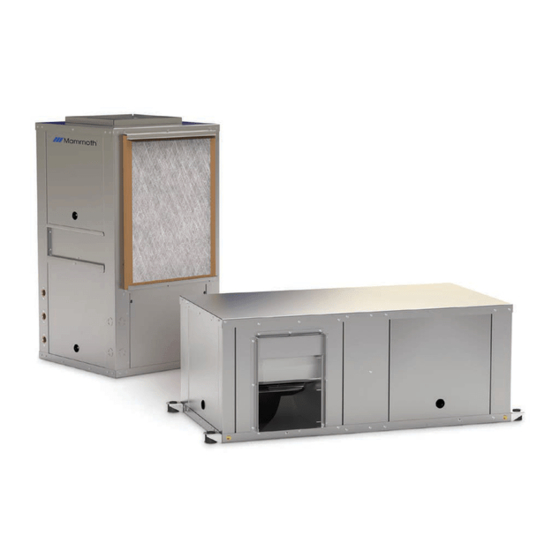
- Page 1 INSTAllATION, OPerATION ANd MAINTeNANCe MANuAl HydroBank ® Compact, Single Stage Water Source Heat Pumps ½ to 6 Tons – Horizontal and Vertical MAMM-WSHP-IOM-1MSA (October 2014) - PN 7144926...
-
Page 2: Table Of Contents
Startup ..........................24 General Maintenance ......................25 Troubleshooting ........................26 Physical Data and Operating Limits ...................27 Operating Pressures and Temperatures ................28 Electrical Data ........................34 Blower Performance Tables ....................38 Typical Wiring Diagrams.....................40 Unit Checkout Sheet ......................48 HydroBank MS Installation and Operation Manual MAMM-WSHP-IOM-1MSA (October 2014) -
Page 3: Introduction
It could also be used to alert against unsafe practices. IMPORTANT: Indicates a situation that could result in equipment or property-only damage. HydroBank MS Installation and Operation Manual MAMM-WSHP-IOM-1MSA (October 2014) -
Page 4: Nomenclature
G = Geothermal Range E = End Digit 11: Controls E = Stand-Alone B = BACnet® L = L ® M = ModBus® N = Metasys® N2 by JCI X = Special HydroBank MS Installation and Operation Manual MAMM-WSHP-IOM-1MSA (October 2014) - Page 5 CBR = Compressor & Blower Monitor Relays CPM = Compressor & Phase Monitor BPM = Blower & Phase Monitor CBP = Compressor, Blower & Phase Monitor YYY = None (standard) XXX = Special HydroBank MS Installation and Operation Manual MAMM-WSHP-IOM-1MSA (October 2014)
-
Page 6: General Information
Make sure the unit is first returned to its normal upright position for at least 24 hours before operating. HydroBank MS Installation and Operation Manual MAMM-WSHP-IOM-1MSA (October 2014) -
Page 7: Horizontal Unit Installation
Line voltage power wiring 3/8 threaded rod (by others) Flexible duct connector Rubber isolators (supplied) (by others) Fender washer (by others) Condensate drain with trap (by others) Double hex nuts (by others) HydroBank MS Installation and Operation Manual MAMM-WSHP-IOM-1MSA (October 2014) - Page 8 13. Slide the blower housing and motor assembly verti- closed off but can only be reopened to the proper position cally upward and out of the unit. for the flow required. HydroBank MS Installation and Operation Manual MAMM-WSHP-IOM-1MSA (October 2014)
- Page 9 Figure 6: ASHRAE AND SMACNA Suggested Supply and Return Air Ducting Return air located away from unit fan Two 90 degree turns prior to intake Flexible connectors Acoustic thermal lining Ductwork supported independently from unit HydroBank MS Installation and Operation Manual MAMM-WSHP-IOM-1MSA (October 2014)
-
Page 10: Vertical Unit Installation
Condensate drain pipe with or controls wiring vent by others (vertical vent by others (vertical units are internally trapped) Line voltage power wiring Line voltage power wiring Isolation pad (by others) HydroBank MS Installation and Operation Manual MAMM-WSHP-IOM-1MSA (October 2014) - Page 11 Figure 10: ASHRAE AND SMACNA Suggested Supply and Return Air Ducting Acoustic thermal lining Return air located away from unit fan Two 90 degree turns prior to intake Ductwork supported independently from unit Flexible connectors HydroBank MS Installation and Operation Manual MAMM-WSHP-IOM-1MSA (October 2014)
-
Page 12: Discharge Duct Sizing Considerations
Table 1 and Table 2 to the right. Table 1: Horizontal unit discharge duct sizing - inches All Mammoth units are tested for airflow as part of our ISO/ARI certification program. It is possible to have Minimum... - Page 13 2%. wiring Table 3: Operating voltages Minimum Maximum Power wiring 208-230/60/3 197 volts 253 volts 460/60/3 414 volts 506 volts 380-415/50/3 342 volts 418 volts 575/60/3 515 volts 632 volts HydroBank MS Installation and Operation Manual MAMM-WSHP-IOM-1MSA (October 2014)
-
Page 14: Optional Water Side Economizer Piping And Control
Water in from loop Unit condensate drain Water out to loop Water in from WSE WSE condensate drain (with trap) Water in from WSE Unit and WSE condensate drains Water out to loop HydroBank MS Installation and Operation Manual MAMM-WSHP-IOM-1MSA (October 2014) -
Page 15: Hot Gas Bypass Option
R and H terminals on the termi- nal block located inside the control panel. See the wiring diagram below. Hot gas reheat coil Hot gas reheat valve Figure 17: Hot Gas Reheat Wiring HydroBank MS Installation and Operation Manual MAMM-WSHP-IOM-1MSA (October 2014) -
Page 16: Motorized Shutoff Valve Option
Override of the unoccupied mode from the thermo- ate. After 120 seconds, the fan, reversing valve and stat for 2 hours (compatible Mammoth thermostat compressor are able to operate after a short time delay. required) HydroBank MS Installation and Operation Manual MAMM-WSHP-IOM-1MSA (October 2014) - Page 17 “RST”. When a man- After 10 seconds, the unit goes into lockout mode. ual reset is selected, the unit stays in lockout until it is manually reset by interrupting power or by removing the HydroBank MS Installation and Operation Manual MAMM-WSHP-IOM-1MSA (October 2014)
- Page 18 “TEST” and “TEST IN” terminals, the random start time delay and the compressor’s five minutes of anti-short cycle time delay will be ignored. However, the two, four and six second HydroBank MS Installation and Operation Manual MAMM-WSHP-IOM-1MSA (October 2014)
-
Page 19: Thermostat Wiring
The HP-5 microprocessor control is designed to operate See Figure 12 and Figure 13 on page 13. A remov- with wall thermostats sold by Mammoth. It can be used able terminal block simplifies hookup. See Figure 20. with other heat pump thermostats but some features To remove it, gently pull it straight out from the control may not be available. - Page 20 Thermostat Wiring Figure 22: Thermostat Wiring With Override and Night Setback Figure 23: Thermostat Wiring - Emergency Shutdown Mode With Override HydroBank MS Installation and Operation Manual MAMM-WSHP-IOM-1MSA (October 2014)
- Page 21 Thermostat Wiring Figure 24: Thermostat Wiring - Emergency Shutdown Mode Without Override HydroBank MS Installation and Operation Manual MAMM-WSHP-IOM-1MSA (October 2014)
-
Page 22: Epic™ Ddc Controls
Leaving source water temperature sensor • Emergency shutdown dry contact • Remote start/stop dry contact • Compressor alarm dry contact • Compressor lockout dry contact • Dirty filter dry contact • Fan proof dry contact HydroBank MS Installation and Operation Manual MAMM-WSHP-IOM-1MSA (October 2014) -
Page 23: Cleaning And Flushing The Water System
9. Check the pressure gauge at the pump suction and temperatures stabilized, each of the units will be manually adjust the makeup to hold the same posi- ready for check, test, startup, and water balancing. HydroBank MS Installation and Operation Manual MAMM-WSHP-IOM-1MSA (October 2014) -
Page 24: Startup
5. Measure the temperature difference between enter- ing and leaving water. It should be approximately 4. Clean up all debris. 1½ times greater than the heating mode tempera- ture difference (see Step 6). HydroBank MS Installation and Operation Manual MAMM-WSHP-IOM-1MSA (October 2014) -
Page 25: General Maintenance
On units equipped with Mammoth EPiC controls, a warning will be indicated when filters need changing. If the filters are not changed, the EPiC control will go into HydroBank MS Installation and Operation Manual MAMM-WSHP-IOM-1MSA (October 2014) -
Page 26: Troubleshooting
Recover refrigerant and re-charge to nameplate. Low discharge Too high of air flow Check fan motor speed selection and airflow. temp in heating Dirty air filter restricting air flow to space Replace or clean. HydroBank MS Installation and Operation Manual MAMM-WSHP-IOM-1MSA (October 2014) -
Page 27: Physical Data And Operating Limits
Maximum Water Temperature 110°F 90°F 110°F 90°F Minimum Entering Air Temperature 65°F 50°F 65°F 60°F Minimum Ambient Air Temp 50°F 50°F 50°F 50°F Maximum Entering Air Temperature 100°F 80°F 100°F 90°F HydroBank MS Installation and Operation Manual MAMM-WSHP-IOM-1MSA (October 2014) -
Page 28: Operating Pressures And Temperatures
137-147 298-318 6-11 7-12 9-11 19-25 161-171 360-380 12-17 33-39 141-151 424-444 6-11 11-16 15-17 18-24 Out of Range 141-151 403-423 6-11 9-14 10-12 18-24 141-151 395-415 6-11 8-13 8-10 18-24 HydroBank MS Installation and Operation Manual MAMM-WSHP-IOM-1MSA (October 2014) - Page 29 5-10 8-13 8-10 19-25 160-170 361-381 12-17 33-39 139-149 417-437 5-10 12-17 13-15 18-24 10.5 Out of Range 139-149 397-417 5-10 10-15 9-11 18-24 12.6 139-149 389-409 5-10 9-14 8-10 18-24 HydroBank MS Installation and Operation Manual MAMM-WSHP-IOM-1MSA (October 2014)
- Page 30 5-10 8-10 20-26 154-164 372-392 17-22 8-13 36-42 12.6 133-143 403-423 12-17 8-13 13-15 18-24 18.0 Out of Range 133-143 384-404 12-17 7-12 9-11 18-24 21.6 133-143 376-396 12-17 6-11 18-24 HydroBank MS Installation and Operation Manual MAMM-WSHP-IOM-1MSA (October 2014)
- Page 31 10-12 19-25 161-171 356-376 14-19 8-10 32-38 136-146 297-317 8-10 19-25 165-175 360-380 15-20 33-39 140-150 422-442 5-10 13-15 17-23 Out of Range 140-150 402-422 9-11 17-23 140-150 394-414 8-10 17-23 HydroBank MS Installation and Operation Manual MAMM-WSHP-IOM-1MSA (October 2014)
- Page 32 32-38 12.6 137-147 291-311 8-13 8-10 19-25 161-171 350-370 13-18 32-38 141-151 414-434 12-17 13-15 18-24 Out of Range 10.5 141-151 394-414 10-15 9-11 18-24 12.6 141-151 386-406 9-14 8-10 18-24 HydroBank MS Installation and Operation Manual MAMM-WSHP-IOM-1MSA (October 2014)
- Page 33 6-11 6-11 8-10 21-27 156-166 374-394 15-20 37-43 12.6 136-146 405-425 6-11 10-15 13-15 19-25 18.0 Out of Range 136-146 385-405 6-11 8-13 9-11 19-25 21.6 136-146 377-397 6-11 7-12 19-25 HydroBank MS Installation and Operation Manual MAMM-WSHP-IOM-1MSA (October 2014)
-
Page 34: Electrical Data
23.0 27.4 208/230-3-60 10.9 16.5 19.2 460-3-60 10.1 208/230-1-60 24.9 34.1 40.3 208/230-3-60 16.6 25.8 30.0 460-3-60 10.5 12.3 208/230-1-60 27.2 36.4 43.2 208/230-3-60 19.3 28.5 33.3 460-3-60 66.1 11.6 13.7 HydroBank MS Installation and Operation Manual MAMM-WSHP-IOM-1MSA (October 2014) - Page 35 *NEUTRAL CONNECTION REQUIRED! All 460 VAC units with constant-torque ECM motors require a four-wire power supply with neutral. The motor is 265-277V/1Ph and is wired between one hot leg and neutral. HydroBank MS Installation and Operation Manual MAMM-WSHP-IOM-1MSA (October 2014)
- Page 36 23.0 27.4 208/230-3-60 10.9 16.5 19.2 460-3-60 10.1 208/230-1-60 24.9 34.1 40.3 208/230-3-60 16.6 25.8 30.0 460-3-60 10.5 12.3 208/230-1-60 27.2 36.4 43.2 208/230-3-60 19.3 28.5 33.3 460-3-60 66.1 11.6 13.7 HydroBank MS Installation and Operation Manual MAMM-WSHP-IOM-1MSA (October 2014)
- Page 37 *NEUTRAL CONNECTION REQUIRED! All 460 VAC units with constant-torque ECM motors require a four-wire power supply with neutral. The motor is 265-277V/1Ph and is wired between one hot leg and neutral. HydroBank MS Installation and Operation Manual MAMM-WSHP-IOM-1MSA (October 2014)
-
Page 38: Blower Performance Tables
1,900 1,875 1,848 1,821 1,793 1,768 1,743 1,718 1,693 1,658 1,621 1,562 1,496 1,429 1,345 1,246 1,149 1,090 2,396 2,380 2,365 2,325 2,285 2,246 2,200 2,129 2,057 1,985 1,913 1,839 1,753 1,656 1,558 1,459 1,359 1,258 HydroBank MS Installation and Operation Manual MAMM-WSHP-IOM-1MSA (October 2014) - Page 39 2,256 2,241 2,225 2,209 2,189 2,170 2,155 2,138 2,120 2,102 2,085 2,069 2,056 2,043 2,007 1,953 1,898 2,385 2,370 2,355 2,336 2,318 2,300 2,283 2,270 2,258 2,242 2,225 2,195 2,147 2,098 2,031 1,964 1,896 HydroBank MS Installation and Operation Manual MAMM-WSHP-IOM-1MSA (October 2014)
-
Page 40: Typical Wiring Diagrams
Typical Wiring Diagrams Typical Wiring Diagrams Wiring Diagram - PSC Motor, Single-Phase 208-230 or 277V/1PH/60H HydroBank MS Installation and Operation Manual MAMM-WSHP-IOM-1MSA (October 2014) - Page 41 Typical Wiring Diagrams Wiring Diagram - PSC Motor , Three-Phase 208-230 or 460V/3PH/60H HydroBank MS Installation and Operation Manual MAMM-WSHP-IOM-1MSA (October 2014)
- Page 42 Typical Wiring Diagrams Wiring Diagram - Constant-Torque ECM Motor, Single-Phase 208-230V/1PH/60H HydroBank MS Installation and Operation Manual MAMM-WSHP-IOM-1MSA (October 2014)
- Page 43 Typical Wiring Diagrams Wiring Diagram - Constant-Torque ECM Motor, Single-Phase 277V/1PH/60H HydroBank MS Installation and Operation Manual MAMM-WSHP-IOM-1MSA (October 2014)
- Page 44 Typical Wiring Diagrams Wiring Diagram - Constant-Torque ECM Motor, Three-Phase 208-230V/1PH/60H HydroBank MS Installation and Operation Manual MAMM-WSHP-IOM-1MSA (October 2014)
- Page 45 Typical Wiring Diagrams Wiring Diagram - Constant-Torque ECM Motor, Three-Phase 460V/1PH/60H HydroBank MS Installation and Operation Manual MAMM-WSHP-IOM-1MSA (October 2014)
- Page 46 Typical Wiring Diagrams Wiring Wiring Diagram - EPiC DDC 560 Controller HydroBank MS Installation and Operation Manual MAMM-WSHP-IOM-1MSA (October 2014)
- Page 47 Typical Wiring Diagrams Diagram - EPiC DDC 583 Controller with Analog Outputs HydroBank MS Installation and Operation Manual MAMM-WSHP-IOM-1MSA (October 2014)
-
Page 48: Unit Checkout Sheet
Liquid Line Leaving Condenser Temp _______ Liquid Subcooling _______ Volts/Amps Phase Compressor Volts _____ _____ _____ Compressor Amps _____ _____ _____ Blower Volts _____ _____ _____ Blower Amps _____ _____ _____ HydroBank MS Installation and Operation Manual MAMM-WSHP-IOM-1MSA (October 2014) - Page 52 CES Group is a leader in innovative custom and engineered HVAC solutions for commercial, industrial and critical environments through our brands Eaton-Williams, Governair, Huntair, Mammoth, Temtrol, Venmar CES and Ventrol. CES Group, LLC is a subsidiary of Nortek, Inc., a glob al diversified company whose many market leading brands deliver broad capabilities and a wide array of innovative, technology-driven products and solutions for lifestyle improvements at home and at work.
Need help?
Do you have a question about the HydroBank MS and is the answer not in the manual?
Questions and answers