Sailor 6215 VHF DSC Radio User & Installation Manual
Vhf radio
Hide thumbs
Also See for SAILOR 6215 VHF DSC Radio:
- User & installation manual (104 pages) ,
- Installation manual (2 pages)
Table of Contents
Advertisement
Advertisement
Table of Contents

Related Manuals for Sailor SAILOR 6215 VHF DSC Radio


Summary of Contents for Sailor SAILOR 6215 VHF DSC Radio
- Page 1 USER & INSTALLATION MANUAL SAILOR 6215 VHF DSC...
- Page 3 Thrane & Thrane A/S SAILOR 6215 VHF DSC Radio User and installation manual Document number: TT98-128471-THR-C Release date: February 3, 2010...
- Page 4 Disclaimer Any responsibility or liability for loss or damage in connection with the use of this product and the accompanying documentation is disclaimed by Thrane & Thrane. The information in this manual is provided for information purposes only, is subject to change without notice and may contain errors or inaccuracies.
-
Page 5: Safety Warning
Safety warning The following general safety precautions must be observed during all phases of operation, service and repair of this equipment. Failure to comply with these precautions or with specific warnings elsewhere in this manual violates safety standards of design, manufacture and intended use of the equipment. -
Page 6: Emergency Calls
Emergency calls L L L L L if if if if ift C t C t C t Cov ov ov ov over er er er er P P P P P r r r r r e e e e e s s s s s s RED Button s RED Button s RED Button s RED Button... - Page 7 Preface Radio for occupational use The SAILOR 6215 VHF DSC fulfils the requirements of the EC directive 1999/5/EC, Radio and Telecommunications Terminal Equipment and is intended for use in maritime environment. SAILOR 6215 VHF DSC is designed for occupational use only and must be operated by licensed personnel only.
-
Page 9: Table Of Contents
Table of Contents Chapter 1 Introduction VHF radio with DSC ............1 Chapter 2 Operation General use and navigation ..........6 VHF radio communication ..........12 HI/LO transmission power ..........18 Watch ................19 Scan .................20 Radio setup ..............22 DSC calls ................25 Phone book ...............41 Loudhailer with talk-back .......... - Page 10 Table of Contents Chapter 4 Service & maintenance Contact for support ............65 Maintenance ..............65 Equipment and accessories ..........71 Warranty ................71 App. A Technical specifications App. B Maritime channels App. C Declaration of conformity Glossary ..................83 Index ..................85 viii...
-
Page 11: Chapter 1 Introduction
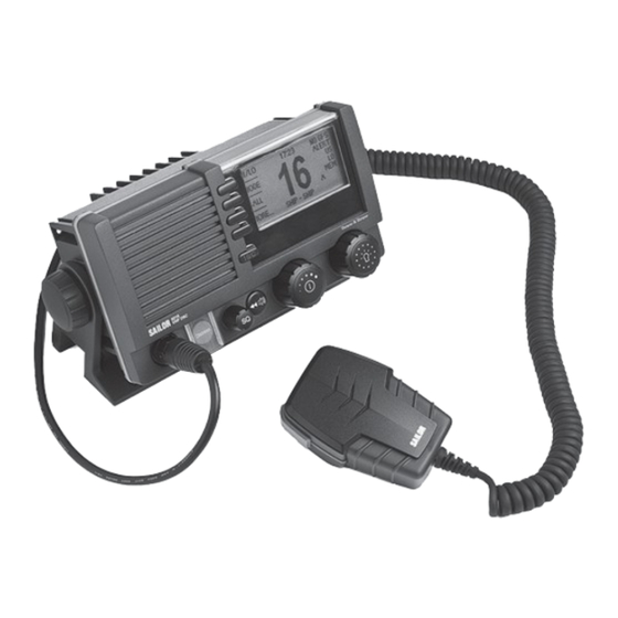
Chapter 1 Introduction VHF radio with DSC SAILOR 6215 VHF DSC, your new SAILOR VHF radio with full DSC functionality, is approved to R&TTE and is waterproof to the IPx8 and IPx6 standard. As part of the required safety equipment, use the SAILOR 6215 VHF DSC in an emergency situation. - Page 12 Chapter 1: Introduction Controls on the front plate 1. Loudspeaker. 2. Four soft keys with function title in the display. 3. Quick selection key for channel 16 and the programmed preference channel. 4. Large display. 5. Connector for Handmicrophone or handset. 6.
- Page 13 Chapter 1: Introduction SAILOR 6215 VHF DSC display The picture shows the display after start-up. The display holds various fields of information, HI/LO GPS Position depending on the currently WATCH selected function. CALL MORE... DISTRESS/CALL 1. Action line containing information relevant for the currently selected function.
- Page 14 Chapter 1: Introduction VHF radio with DSC...
-
Page 15: Chapter 2 Operation
Chapter 2 Operation Note Before using the VHF radio make sure that the VHF antenna, power and other external equipment are connected properly. For instructions see chapter Installation on page 49. In this chapter you find detailed instructions and guidelines for: •... -
Page 16: General Use And Navigation
Chapter 2: Operation General use and navigation Power on and speaker volume The VHF radio has a dual-function on/off wheel knob for power on/off and volume control. • To power on the VHF radio press the on/off wheel knob. • To power off the VHF radio, press and hold the on/off wheel knob and follow the instructions in the display. - Page 17 Chapter 2: Operation DSC and MMSI number When the VHF radio is powered on for the first time, you must enter the vessel’s MMSI number. Hereafter the MMSI number is briefly displayed after power up. The MMSI is a unique, 9-digit identifier assigned to your ship. Important The MMSI number must be programmed into the VHF radio to use any DSC functionality.
- Page 18 MMSI is not programmed. Position and MMSI Information To display position and MMSI information for the SAILOR 6215 VHF DSC radio, do as follows: 1. Press the soft key POS. If it is not in the display, press the soft key MORE until POS appears.
-
Page 19: Adjusting The Squelch
Chapter 2: Operation Speaker devices The VHF radio can be equipped with the following speaking devices: • SAILOR 6202 Handmicrophone with a PTT (Push To Talk) button. • Handset with a microphone, ear piece and a PTT button. The volume in the ear piece can be adjusted, for details see Controller setup on page 10. - Page 20 Chapter 2: Operation Soft key Function SCAN Scanning function HAIL Loudhailer Fog horn PBOOK Phone book SETUP Setup pages for RADIO, HAILER/FOG, SYSTEM, CONTROLLER and DSC The functions of the SAILOR 6215 GPS Position HI/LO VHF DSC are accessed and set WATCH using the four soft keys to the left of the display.
- Page 21 Chapter 2: Operation 3. Turn the selector wheel knob to go to a setting, then press the selector wheel knob to change the setting. 4. Press EXIT to return to normal radio operation. Parameter Description Handset 1 vol: Adjust earpiece volume for handset 1: OFF, 1 to 14 Note: Default setting is OFF.
-
Page 22: Vhf Radio Communication
Chapter 2: Operation VHF radio communication In this section of the manual you find information on • Basic VHF operation • VHF channels • Programming a call channel • Naming a channel Basic VHF operation You can make VHF calls using the Handmicrophone or another speaking device. - Page 23 Chapter 2: Operation Receiving a radio telephone call on channel 16 When you hear your call name in the loudspeaker, GPS Position HI/LO proceed as follows: WATCH 1. An RX symbol shows that the radio is receiving on CALL the working channel displayed. MORE...
- Page 24 Chapter 2: Operation 5. Say: “This is [your ship’s name]”. 6. Say: “Over.” and release the PTT key to listen. An GPS Position HI/LO RX symbol shows that the radio is receiving on WATCH the working channel displayed CALL 7. When answered, agree upon a working channel MORE...
- Page 25 Chapter 2: Operation VHF channel table Description Weather (WX) Weather channels have the prefix W. (For US and CA channels only.) Private (PRIV) Up to 40 user-defined private channels. Contact your dealer for programming private channels. Programming a call channel To program a call channel (or quick selection), do as follows: 1.
- Page 26 Chapter 2: Operation 5. Press the soft key OK to confirm the entered value PROGRAM and to leave edit mode. BACK 6. Press EXIT to return to return to the standard VHF CLEAR display. CANCEL NEW_ Display for non-VHF applications When the radio is used for functions other than VHF, the display is arranged differently.
- Page 27 Chapter 2: Operation Engagement status The radio is considered engaged when an active DSC-initiated communication is ongoing, or communication is active on non-DSC initiated VHF operation: • A new channel selected • PTT pressed or, • Voice signal received The engagement state is used to prohibit incoming DSC calls from taking over control of the transmitter channel, disrupting ongoing communication.
-
Page 28: Hi/Lo Transmission Power
Chapter 2: Operation HI/LO transmission power Press the soft key HI/LO to toggle the transmit power between low (1 W) and high (25 W). If LO is not displayed, the transmit power is HI. US channels: Local mode, 10 dB attenuation To attenuate to the incoming signal, do as follows: 1. -
Page 29: Watch
Chapter 2: Operation Watch The SAILOR 6215 VHF DSC radio Dual watch Triple watch can be set to dual watch or triple watch. In dual watch, the working channel and channel 16 are watched. In triple watch the working channel, channel 16 and the programmed call channel are watched. -
Page 30: Scan
Chapter 2: Operation Scan The radio has a scanning function for tagged channels. Any available channel, including weather and private channels, can be tagged and added to the scanning sequence. As default the radio scans with priority scanning of channel 16. If a signal is received while in any scanning mode, only channel 16 continues to be watched. - Page 31 Chapter 2: Operation US channels: Watch alarms for NOAA Weather alerts Note NOAA weather channels are available in the waters of USA and Canada only. You can turn on or off an independent watch alarm for a specific weather channel. To turn on or off an independent NOAA weather alarm do as follows: 1.
-
Page 32: Radio Setup
Chapter 2: Operation Radio setup In the RADIO SETUP you set scan and watch mode, select the channel table and can set and view the ATIS code. To change a setting in the RADIO SETUP, do as follows: 1. Press the soft key SETUP. If it is not in the display, press the soft key MORE until SETUP appears. - Page 33 Chapter 2: Operation Para- Description meter Priority ON: All channels tagged for scanning are scanned while monitoring Scan channel 16. (default). OFF: Only the channels tagged for scanning are scanned in sequence, not channel 16, unless it is tagged for scanning. Channel Channel Channel...
- Page 34 Chapter 2: Operation Para- Description meter ATIS The ATIS code (Automatic Transmitter Identification System) is used code for identification to marine coast and inland stations and its use is mandatory in a number of European inland waterways such as e.g. the river Rhine.
-
Page 35: Dsc Calls
Chapter 2: Operation DSC calls In this section of the manual you find information on: • Sending, acknowledgment and cancel own distress • Receiving distress calls • DSC calls for communication • DSC setup Sending, acknowledgment and cancel own distress Sending a distress message To send a distress message do as follows: 1. -
Page 36: Further Information
Chapter 2: Operation Having pressed the red distress button and sent the DISTRESS (DETAIL) PAUSE distress message, press the soft key INFO to display STATION: 123456789 ANNUL NAT: UNDESIGNATED further information: LAT: 23°23.3234 N INFO LON: 123°23.3234 W • STATION: shows the radio’s MMSI number. POS UTC: 12:34 MORE MODE: TELEPHONY... - Page 37 Chapter 2: Operation 3. Press the selector wheel knob to accept the selected nature of distress. 4. Then lift the cover of the red distress button and push the Distress button for 3 seconds. Acknowledgement of own distress When the SAILOR 6215 VHF DSC receives an OWN DISTRESS acknowledgement of distress from another vessel or DISTRESS ACKNOWL .
- Page 38 Chapter 2: Operation 2. Press the soft key YES to go ahead with the WARNING cancelling process. At this stage you have the option to press the soft key NO to return to distress DO YOU WANT TO CANCEL YOUR sending procedure.
- Page 39 Chapter 2: Operation Receiving distress calls When the radio receives a distress call, the 2-tone alarm sounds. Types of distress calls are DISTRESS, DISTRESS ACK, CALL RECEIVED DISTRESS RELAY and DISTR. RELAY ACK. DISTRESS CALL CANCEL FROM: 219005678 TO: ALL SHIPS 1.
- Page 40 Chapter 2: Operation Distress call log As long as you are part of a distress session, i.e. you Received Distress 1/3 EXIT have not pressed QUIT, you receive distress messages 2009 -8-12 10 :11 DISTRESS CALL and can track all distress messages for the current FROM: 219005678 distress event.
- Page 41 Chapter 2: Operation 2. Press and turn the selector wheel knob to select other call types or set the details for the call: • Type: DSC call type Category Individual Routine (default) or safety calls, calls to a ship or a station Group calls Routine All ship calls...
- Page 42 Chapter 2: Operation Display for a DSC session 1. Head line showing the type of call that INDIVIDUAL TX QUIT initiated the DSC session, see table WAIT FOR ACKNOWLEDGE below for a list of available head lines. HOLD MMSI: 278888913 ELAPSED TIME 0:12 INFO 2.
- Page 43 Chapter 2: Operation Headline Explanation ALL SHIPS TX/RX You have sent / received an all ships call GROUP TX/RX You have sent / received a group call INDIVIDUAL You have either sent a call request to a station to TX/RX establish contact, or another station has made a call to you to establish contact.
- Page 44 Chapter 2: Operation Soft key Radio function Constructs a reply to the caller if an individual call is UNABLE received which is not compatible with the radio modes. Silences alarms. Any key silences the alarm but this SILENT soft key function will do only this. Acknowledges a received call request with the suggested parameters.
- Page 45 Chapter 2: Operation Detail information for DSC sessions (soft key: INFO) A DSC session is updated based on DSC calls received or transmitted. Press the soft key INFO to show the details for the current session. For distress events a sequence of calls may contribute to the complete view and status of the session.
- Page 46 Chapter 2: Operation Details —other calls Explanation Longitude position of station in distress POS UTC Time of position Receiving DSC calls If the radio is IDLE (not engaged in another session) and a DSC call is received the call details are shown on the display. The following options (soft keys) are available: Soft key Radio function...
- Page 47 Chapter 2: Operation soon the current DSC session is terminated. The call with the highest priority (importance for safety or life) is shown first. Handling a background session The equipment is designed with the possibility to control a DSC session simultaneously with a VHF communication session.
- Page 48 Chapter 2: Operation DSC call logs To display a DSC call log in the DSC CALL LOGS, do as follows: 1. Press the soft key SETUP. If it is not in the display, press the soft key MORE until SETUP appears. 2.
- Page 49 Chapter 2: Operation 4. Press EXIT to return to normal radio operation. DSC setting Description Position Info Available position information. Here you can enter position data, see also Position and MMSI Information on page 8. Auto-Ack Test Auto-acknowledgement of test DSC messages OFF - Disabled ON –...
- Page 50 Chapter 2: Operation DSC setting Description Auto-switch Enable automatic channel switching on reception Channel of DSC calls with subsequent communication channel information, while the radio is not engaged (for calls other than individual station calls of category distress or urgency). ON (default) OFF - LCK icon indicates that the channel is locked and must be selected manually...
-
Page 51: Phone Book
Chapter 2: Operation Phone book Use the phone book when making a DSC call. You can enter up to 50 contacts. A contact has the following details: • Name (up to 20 characters) • Type (SHIP, GROUP or COAST STATION) •... - Page 52 Chapter 2: Operation Adding a contact to the phone book To add a contact to the phone book do as follows: 1. Press the soft key PBOOK. If it is not in the display, press the soft key MORE until PBOOK appears in the display. 2.
- Page 53 Chapter 2: Operation Editing a contact 1. Press the soft key PBOOK. If it is not in the display, press the soft key MORE until PBOOK appears. 2. Press the soft key EDIT. 3. Press and turn the selector wheel knob to browse through the details of the contact.
-
Page 54: Loudhailer With Talk-Back
Chapter 2: Operation Loudhailer with talk-back The SAILOR 6215 VHF DSC supports a loudhailer with a talk-back function. Important When the hailer is in talk-back mode and a radio signal is received, the radio signal has a higher priority and is heard in the loudspeaker. -
Page 55: Automatic Foghorn
Chapter 2: Operation Automatic foghorn The SAILOR 6215 VHF DSC has an automatic fog horn application with several foghorn patterns. Once started, it runs in the background while running any other application. The fog horn may be combined with the loudhailer talk- back mode. - Page 56 Chapter 2: Operation 2. Use the selector wheel knob to browse through the patterns available. UNDERWAY 1 long blast every 120 s STOP 2 long blasts every 120 s SAIL 1 long blast followed by 2 short blasts every 120 s 1 long blast followed by 3 short blasts every 120 s AGROUND...
-
Page 57: Hailer And Fog Horn Setup
Chapter 2: Operation Hailer and Fog horn setup To change a setting in the HAILER/FOGHORN SETUP, do as follows: 1. Press the soft key SETUP. If it is not in the display, press the soft key MORE until SETUP appears. 2. -
Page 58: Replay Function
Chapter 2: Operation Replay function Replay allows the operator to playback received voice messages in the loudspeaker. Recording is activated automatically when a signal is received. Recording is not possible during playback. Up to 60 tracks or 90 seconds can be handled. The recorded channel is displayed. -
Page 59: Chapter 3 Installation
Chapter 3 Installation In this chapter you find information and guidelines for: • Unpacking the SAILOR 6215 VHF DSC • Installing the VHF radio • Power, VHF antenna and external equipment Unpacking the SAILOR 6215 VHF DSC The following items are included in the delivery of a SAILOR 6215 VHF DSC: •... -
Page 60: Installing The Vhf Radio
Provide space enough to access the front panel connectors and for installing a cradle for the speaking device. Provide at least 120 mm space at the back of the SAILOR 6215 VHF DSC radio to allow free air circulation. Compass safe distance Make sure that the VHF radio is far enough from any magnetic compass to avoid influence of the loudspeaker magnet on the compass reading. - Page 61 Chapter 3: Installation SAILOR 6215 VHF DSC with U mounting bracket The mounting bracket and two knobs are included in the delivery. Desktop mounting Installing the VHF radio...
- Page 62 Chapter 3: Installation Overhead mounting Installing the VHF radio...
- Page 63 Chapter 3: Installation Mounting with U mounting bracket To mount the VHF radio as tabletop, do as follows: 1. Find a suitable location for the VHF radio. Check that the space is wide/deep enough to accommodate the VHF radio. 2. Fasten the bracket with 4 screws (included in the delivery.)
- Page 64 Chapter 3: Installation SAILOR 6215 VHF DSC for flush mount You can mount the VHF radio to a flat surface, e.g. an instrument panel. The flush mount installation kit is included in the delivery. R2.5mm x 4 177mm Remove material from shaded area only! Important The scaling in the above drawing is not 1:1.
- Page 65 Chapter 3: Installation 1. Find a suitable location for the VHF radio. Check that the space is deep enough to accommodate the VHF radio and an additional min. 120 mm space for cable entry. 2. Keep free distance to allow free air circulation around the VHF radio and to allow sufficient space for access to cables, see the drawing on this page.
- Page 66 Chapter 3: Installation SAILOR 6202 Handmicrophone Handmicrophone with spiral cable and PTT button. Installing the VHF radio...
-
Page 67: Power, Vhf Antenna And External Equipment
Chapter 3: Installation Power, VHF antenna and external equipment 1. ACC connector 2. CTRL connector for control speaker microphone 3. Power, Loudhailer, foghorn and external speaker 4. VHF antenna 5. Ground stud ACC connector Use the connector marked ACC to connect GPS input. The interface for GPS is NMEA 0183 (EN61 162-1 Listener / EN61 162-2 Talker). - Page 68 Chapter 3: Installation NMEA interface description ACC connector NMEA in+ O pin1 NMEA in- O pin2 NMEA out+ O pin3 NMEA out- O pin4 NMEA interface Specifications Impedance: 600 Ohm NMEA input: Max. 2mA at min. level of 2V Load Impedance: > 60 Ohm NMEA output Drive load: <...
- Page 69 Chapter 3: Installation The following sentences are supported: • FSI: All fields are decoded • GGA: UTC, "Position", "quality indicator". All other fields are unused • GLL: UTC, "Position", "Status" and "mode". All other fields are unused • GNS: UTC, "Position" and "mode". All other fields are unused •...
- Page 70 Chapter 3: Installation Power, Loudhailer, foghorn and external speaker Use the connector marked PWR/EXT to connect power, loudhailer and an external speaker. The cable for this connector is part of the delivery. 1. Blue wire: Power - 2. Red isolation on inner connector: loudhailer 3.
- Page 71 Chapter 3: Installation Protection against water ingress Important You must protect the cable connection with rubber vulcanizing tape as shown in the pictures below. This protection prevents water seeping into the VHF radio, cable and connectors. VHF antenna Use the connector marked ANT to connect the VHF antenna to the radio with a 50 Ohm coaxial cable with low loss, e.g.
-
Page 72: System Setup
Chapter 3: Installation Ground stud To ground the radio connect a ground wire from the ground stud of the radio to a suitable grounding point. Use an appropriately sized wire. The ground stud is located above the VHF antenna connector. System setup To change a setting in the SYSTEM SETUP, do as follows: 1. - Page 73 Chapter 3: Installation SYSTEM SETUP Description Inactivity timeout Inactivity time-out to exit functions (e.g. in setup) and return to the application. Range: 1 to 30 minutes, in 1 minute steps Default: 10 min. Password If you need to change the identity of the radio (MMSI number or ATIS code), contact your local dealer.
-
Page 74: Sailor 6201 Handset Cradle (Optional)
Chapter 3: Installation SAILOR 6201 Handset cradle (optional) Drilling plan * 120 Space for handset access This Handset has a hook-on/off function, which is activated by a small magnet embedded in the cradle. The cradle must be installed as illustrated in order to ensure the hook-on/off functionality of the Handset. -
Page 75: Chapter 4 Service & Maintenance
Maintenance Preventive maintenance Maintenance of the SAILOR 6215 VHF DSC radio can be reduced to a maintenance check at each visit of the service staff. Inspect the radio for mechanical damages, salt deposits, corrosion and any foreign material. Due to its robust construction and ruggedness the radio has a long lifetime. -
Page 76: Troubleshooting Guide
Chapter 4: Service & maintenance DSC self test To run a control routine DSC self test, do as follows: 1. Press the soft key SETUP. If it is not in the display, press the soft key MORE until SETUP appears. 2. - Page 77 Chapter 4: Service & maintenance Action Symptom Remedy No commu- Check the antenna installation. nication loudspeaker Check antenna cable. is mute. Check handset/Handmicrophone and cable. Position If the VHF, despite being connected to a requested. GPS/position source, prompts for entering the position and time information, the automated update has most likely been lost either due to missing data on the line, broken cabling or the...
- Page 78 Chapter 4: Service & maintenance Action Symptom Remedy DSC routine Check the DSC function regularly. Verify the testing complete DSC installation, with antennas, by transmitting a Safety Test call to another station (coast or ship). The test call is generated using the DSC call flow via menu CALL.
- Page 79 Chapter 4: Service & maintenance Action Symptom Remedy Radio time DSC logs are A wrong radio time indication should occur sorted with only if GPS position source is not connected or wrong time providing correct time data. A valid GPS time stamp or signal will update the UTC time used for time radio time is...
- Page 80 Chapter 4: Service & maintenance Action Symptom Remedy Device failure If any of the checks and tests described in this section do not assist in resolving the difficulties experienced in the operation and/or performance of the VHF installation, a fault may have developed in the VHF radio itself.
-
Page 81: Equipment And Accessories
Chapter 4: Service & maintenance Equipment and accessories SAILOR 6209 Accessory connection box You can connect the SAILOR 6209 Accessory Connection Box for input from GPS (NMEA) and SAILOR 6201 Handset option. The wire terminal blocks are connected in parallel. 36090 Warranty For repair or replacement of the VHF radio within terms of warranty, contact... - Page 82 Chapter 4: Service & maintenance Warranty...
-
Page 83: Technical Specifications
Appendix A Technical specifications Item Specification Weight SAILOR 6215 transceiver approx. 1.2 kg unit Weight SAILOR 6215 transceiver approx. 1,5 kg including SAILOR 6202 unit Handmicrophone and mounting bracket Dimensions Height: Outer dimension 106 mm, hole height for flush mount 89 mm Width: Outer dimension 190 mm, hole width for flush mount 177 mm Depth: Outer dimension from front of wheel... - Page 84 Appendix A: Technical specifications Item Specification Number of P channels The radio may be programmed with up to 40 private channels that can be managed in all channel modes. Transmit power Hi/Lo: 25 W and <1 W RF output power 25 W +0 dB / - 1.5 dB 1 W +0 dB / - 1.5 dB Modulation...
-
Page 85: Maritime Channels
Appendix B Maritime channels International channels Channels SIMPLEX DUPLEX Channels SIMPLEX DUPLEX Intership Port Port Public Intership Port Port Public 156,050 160,650 156,025 160,625 156,100 160,700 156,075 160,675 156,150 160,750 156,125 160,725 156,200 160,800 156,175 160,775 156 250 160 850 156,250 160,850 156 225 160 825 156,225 160,825... - Page 86 Appendix B: Maritime channels US channels Channels SIMPLEX DUPLEX Channels SIMPLEX DUPLEX Channels 156,050 156,050 162,550 162,400 162,475 156,175 156,175 162,425 156,250 156,250 162,450 156,300 156,300 156,275 156,275 162,500 156,350 156,350 156,325 156,325 162,525 156,400 156,400 156,375 156,375 156,450 156,450 156,425 156,425 156,500 156,500 156,475 156,475...
- Page 87 Appendix B: Maritime channels Bi channels Channels SIMPLEX DUPLEX Channels SIMPLEX DUPLEX Intership Port Port Public Intership Port Port Public 156,050 160,650 156,025 160,625 156,100 160,700 156,075 160,675 156,150 160,750 156,125 160,725 156,200 160,800 156,175 160,775 156,250 160,850 156,225 160,825 156,300 156,300 156,275 160,875 156,350 160,950...
- Page 88 Appendix B: Maritime channels Ca channels Channels SIMPLEX DUPLEX Channels SIMPLEX DUPLEX Channels 156,050 160,650 156,025 160,625 162,550 156,100 160,700 156,075 156,075 162,400 156,150 160,750 156,125 156,125 162,475 156,200 156,200 156,175 156,175 162,425 156,250 156,250 156,225 160,825 162,450 156,300 156,300 156,225 156,225 162,500 156,350 156,350...
- Page 89 Chapter B: Maritime channels Alternative channels If the radio is used in regions where neither of the four described standard channels are allowed, a reduced channel table with international channel designators and frequencies can be made. Contact your local dealer for programming the alternative channels.
- Page 90 Chapter B: Maritime channels...
-
Page 91: Declaration Of Conformity
Appendix C Declaration of conformity The SAILOR 6215 VHF DSC is certified as stated in the “Declaration of Conformity with R&TTE Directive, enclosed in copy on the next page. - Page 92 Appendix C: Declaration of conformity Thrane & Thrane A/S Declaration of Conformity with R&TTE Directive The undersigned of this letter declares that the following equipment complies with the specifications of EC directive 1999/5/EC concerning Radio & Telecommunications Terminal Equipment. Equipment included in this declaration SAILOR 6215 VHF transceiver with class D DSC PN = 626215A...
-
Page 93: Glossary
Glossary Glossary Automatic Identification System, used by ships and Vessel Traffic Services (VTS) principally for identification and locating vessels. ATIS Automatic Transmission Identification System Digital Selective Calling NMEA sentence, essential fix data which provide 3D location and accuracy data. NMEA sentence, Geographic Latitude and Longitude NMEA sentence, Global Positioning System NMEA... - Page 94 Glossary Coordinated Universal Time. The International Atomic Time (TAI) with leap seconds added at irregular intervals to compensate for the Earth’s slowing rotation. Leap seconds are used to allow UTC to closely track UT1, which is mean solar time at the Royal Observatory, Greenwich.
-
Page 95: Index
Index Index Numerics backlight, 1 dim, 6 16/C, 12 Bi, 77 90 s replay, 48 Bi channels, 77 browse channels, 6 ACC connector, 57 accessories, 71 Ca channels, 78 acknowledgement, distress, 27 cable for VHF antenna, 61 action line, display, 3 CALL, 41 activate call... - Page 96 Index channels distress Bi, 77 acknowledgement, 27 Ca, 78 cancelling, 27 international, 75 display, 26 primary, 14 nature, 26 private, 15 power failure, 28 US, 76 received calls, 29 weather, 15 time since activation, 26 Comm Inactivity, 39 distress button, 25 compass safe distance, 50 Distress procedure, iv connector...
- Page 97 Index external speaker cabling, 60 input connector, 60 GPS, 71 handset, 71 NMEA, 62 installation factory defaults, 62 cradle for 6201, 64 flush mount, 54 desktop, 51 FOG, 45 flush mount, 54 foghorn, 1, 45, 46 handset cradle, 64 activate, 41, 45 mounting bracket, 53 connector, 60 overhead, 52...
- Page 98 Index maritime channels, 75 phone book, 41 MAYDAY, iv add contact, 42 message delete a contact, 43 replay, 48 edit a contact, 43 MMSI position change, 63 enter manually, 8 MMSI number position data reviewing, 8 enter manually, 39 MORE, 10 position Info, 39 mounting, 50 power failure...
- Page 99 Index soft key ADD, 42 safety summary, iii CALL, 41 salt deposits, 65 DELETE, 43 scan DSC, 33 add channel, 20 FOG, 45 hang time, 22 HAIL, 44 priority, 23 HORN, 46 remove channel, 20 LOCAL, 18 resume time, 22 MORE, 10 resume, activate, 22 NAME, 15...
- Page 100 Index technical data, 73 warranty, 71 temperature limitation, iii operational, 73 WATCH, 19, 20 storage, 73 watch testing, foghorn, 46 dual and triple, 19 time out dual or triple, 22 non distress, 39 setup, 22 timeout, 63 start, 19 Distress, 39 stop, 19 VHF and other non distress, 39 water ingress, 74...
- Page 102 TT98-128471-THR-C Thrane & Thrane A/S info@thrane.com www.thrane.com • •...
Need help?
Do you have a question about the SAILOR 6215 VHF DSC Radio and is the answer not in the manual?
Questions and answers