Table of Contents
Advertisement
Quick Links
Advertisement
Table of Contents

Related Manuals for Sailor SP3510 VHF

Summary of Contents for Sailor SP3510 VHF
- Page 1 USER MANUAL SAILOR SP3510 VHF...
- Page 2 Emergency procedure • Turn the knob at the top of the radio clockwise. The display lights up showing the last used channel and the battery level. • Select channel 16 (Distress or Safety), press the 16/C key. • Press the PTT and say: —...
- Page 3 Copyright: © 2008 Thrane & Thrane A/S. All rights reserved. Trademark Acknowledgements • SAILOR is a registered trademark of Thrane & Thrane A/S. • Other product and company names mentioned in this manual may be trademarks or trade names of their respective owners.
- Page 4 Precautions Avoid water and salt in the I/O connector and keep it clean frequently. Only use original Thrane & Thrane battery packs. Make sure they are clean and dry before attaching the transceiver. Be careful not to damage any gaskets. Only use the original Thrane &...
- Page 5 Training information SAILOR SP3510 VHF is designed for "occupational use only". It must be operated by licensed personnel only. The SP3510 complies with the FCC RF exposure limits for "Occupational Use Only". • FCC OET Bulletin 65 Supplement C, evaluating compliance with FCC guidelines for human exposure to radio frequency electromagnetic fields.
- Page 6 0641...
-
Page 7: Table Of Contents
Contents Chapter 1 Introduction Your VHF ................1 Performance ...............2 Channels ................2 Chapter 2 Operation Controls ................5 Keys and buttons ..............5 The display .................7 Using the VHF ..............8 Basic functions ..............8 Other functions ..............11 Chapter 3 Batteries Battery level indication ............13 Removing and inserting the battery pack ......13 The battery chargers ............14 Installing the charger ............14... - Page 8 Chapter 5 Equipment and accessories External equipment ............23 List of equipment .............. 23 Connecting external equipment ........23 Impact on radio operation ..........24 Accessorie connector ............24 Accessories ..............25 List of accessories ............. 25 Attaching and removing the belt clip ........ 27 Attaching the lanyard ............
-
Page 9: Chapter 1 Introduction
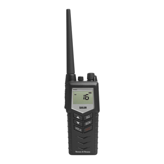
Chapter 1 Introduction Your VHF The SP3510 VHF is designed for flexibility in daily use. It connects easily to external equipment like headsets and fist mikes, making the SP3510 suitable for any noisy environment. Main features: Unique man machine interface, an excellent grip even with gloves, and large tactile buttons. -
Page 10: Performance
Introduction Performance For best performance of the transceiver keep the following in mind: • Keep clear of metal environment. • Hold the transceiver vertically and 10 cm from lips and push the PTT when transmitting. • In receive mode carry the transceiver vertically with belt clips. •... - Page 11 Introduction Channel modes The notes in the following sections list the channel restrictions that apply for each channel mode. Entering and using For information on how to select a channel mode, see configuration mode CHAN on page 17 and on page 18. National frequency regulations shall always be respected and might restrict operation for this type of equipment.
- Page 12 Introduction Canadian channels Notes: • Tx power is limited to 1 W on channels 15, 17, 20, 65, 66 and 77. • The channels 19, 22, 63, 75, 76 and 81 cannot be selected. • The Weather channels (CA W-ch. in the channel table) can only be used in Rx direction.
-
Page 13: Controls
Chapter 2 Operation Controls Keys and buttons 1. On/off/volume 2. Light/Lock 3. Push To Talk (PTT) 4. Up key 5. Down key 6. Hi/Lo output power 7. Squelch 8. Scan 9. Priority channel (16)/ Call channel 10. Loudspeaker/microphone 0740... - Page 14 Operation Key presses Pressing and holding certain keys gives access to additional functions, shown in the table below. Extra long Short press Long press press (1 beep) (2 beeps) (3 beeps) Show next available Run through available Run through item in the list (up or items, or available down).
-
Page 15: The Display
Operation The display The display holds various fields of information, explained below. 1. Current working channel. 2. Current channel mode. 3. “Lo”: Reduced transmitter power. Full transmitter power is not shown in display. 4. Dual/Triple watch activated. 5. Current working channel is marked for scanning. 6. -
Page 16: Using The Vhf
Operation Using the VHF Basic functions Before using the radio, mount the antenna at the top of the Note radio. The antenna is delivered with the radio. Switching the radio on and off • To switch the radio on, turn the knob at the top of the radio clockwise. - Page 17 Operation Activating a call To activate a call to the selected channel, press and hold the PTT button on the side of the radio. The radio transmits as long as the PTT button is pressed. A small Tx sign next to the channel num- ber indicates when the radio is in transmit mode.
- Page 18 Operation Using Dual/Triple watch • To activate Dual/Triple watch, press the SCN key. The display shows “Dual” or “Tri” at the top and “16” at the bottom right. The radio toggles between the selected channel and channel 16 in Dual watch. In Triple watch, the radio shifts between channel 16, the call channel and the selected channel.
-
Page 19: Other Functions
Operation Other functions Programming the Call channel To program the Call channel, do as follows: 1. Press and hold 16/C until the current Call channel number is flashing. 2. Select the channel with 3. Press 16/C to confirm within 3 seconds. Programming the scanning memory To add a channel to the scanning memory, select the channel and then press and hold the SCN key until the display shows MEM at the top. - Page 20 Operation 0703...
-
Page 21: Chapter 3 Batteries
Chapter 3 Batteries Battery level indication When the battery level is low, you should recharge the battery. The radio display shows the battery status. When the battery symbol is empty and flashing, the battery should be recharged as soon as possible. Removing and inserting the battery pack To remove the battery pack, do as follows: 1. -
Page 22: The Battery Chargers
Batteries The battery chargers The chargers has two compartments. CH3507 • A rear compartment only for storing a spare battery. It does not have a charger function. • A front compartment for recharging the battery alone or while attached to the radio. CH3508 •... -
Page 23: Recharging The Battery
Batteries Connecting to power The charger can be supplied from DC or from AC using an AC/DC converter. DC: Connect the 12-24VDC Connection Cable between the DC supply and the connector on the underside of the charger. AC: Connect the AC/DC converter to the connector on the underside of the charger. - Page 24 Batteries 0643...
-
Page 25: Chapter 4 Configuring The Radio
Chapter 4 Configuring the radio Configuration mode Entering and using configuration mode Note The radio is not operational in configuration mode. • To enter configuration mode, press and hold the Light/Lock button while turning on the radio. The bottom line of the display shows the current menu item/setting. •... -
Page 26: List Of Configuration Settings
Configuring the radio List of configuration settings The following settings are available in configuration mode. Name Values Description LIGHT Only Light/Lock button activates the backlight. All keys and buttons, except PTT and volume control, activate the backlight. CHAN International channels. US channels. - Page 27 Configuring the radio Name Values Description SLEEP Enable sleep mode (to minimize power consumption). Sleeps for periods of 1 second after 15 seconds of idle mode. Idle mode is: no signal detected and no operation of the radio. Disable sleep mode. CONTRST 1, 2, 3, 4, 5 Contrast.
- Page 28 Configuring the radio Name Values Description TIME A long press on SQ opens squelch. The squelch level resumes to setting 3 seconds after SQ is released. A long press on SQ opens squelch. The squelch level resumes to setting as soon SQ is released. WORK If the distress or call channel is selected using the 16/C key, any push on...
- Page 29 Configuring the radio Name Values Description 1 _ _ _ _ _ _ _ _ In ATIS programming mode: • Select the digit position with the Light/Lock 1 2 _ _ _ _ _ _ _ button. 1 2 3 _ _ _ _ _ _ •...
- Page 30 Configuring the radio 0643...
-
Page 31: Chapter 5 Equipment And Accessories
Chapter 5 Equipment and accessories External equipment List of equipment The following equipment can be connected to the radio: • SAVOX 400E Push-To Talk unit • SAVOX C500 Fist Mike • SAVOX NC/400 Noise-com • SAVOX HC-E Helmet-com • SAVOX K53004 Helmet unit •... -
Page 32: Impact On Radio Operation
Equipment and accessories When external equipment is connected to the radio, the right side of the display will show a headset. Impact on radio operation The external equipment can have a built-in PTT button, speaker and microphone. Thus a connection has per default the following impact on the radio operation: •... -
Page 33: Accessories
Equipment and accessories Accessories List of accessories The following accessories are delivered with your radio: Accessory Part number Secondary battery (black, rechargeable), B3502 403502A Charger, CH3507 403507A AC/DC converter, length 150cm (100-240V~ /12VDC out) 88-125538 12-24VDC Connection cable, length 150cm 37-124381 Belt clip 62-124320... - Page 34 Equipment and accessories Accessories you may buy Accessory Part number Dual Position Charger CH3508 403508A Leather Case 403500-205 Leather Case Warning! The display must always be kept away from the body to reduce the RF exposure when body worn. 0740...
-
Page 35: Attaching And Removing The Belt Clip
Equipment and accessories Attaching and removing the belt clip To attach the belt clip, slide the belt clip upwards into the rails at the back of the radio until it locks. To remove the belt clip, press the projection at the top of the belt clip to release the lock and slide the belt clip downwards out of the rails. - Page 36 Equipment and accessories 0740...
-
Page 37: Chapter 6 Troubleshooting
Chapter 5 Troubleshooting Displaying errors Some errors result in an error message in the display. These error messages are listed below. Display text Problem Type Actions The battery voltage is Severe. Change/recharge below a critical level, Radio is non- the battery. EMPTY BAT where further operation functional. - Page 38 Troubleshooting 0740...
-
Page 39: Technical Specifications
Appendix A Technical specifications Technical data SP3510 General Item Specification Rx frequency range, landmobile 148.000 - 174.000 MHz Tx frequency range, landmobile 148.000 - 174.000 MHz Rx frequency range, maritime 155.000 - 163.425 MHz Tx frequency range, maritime 155.000 - 161.450 MHz Modulation 16K0G3E Power supply... -
Page 40: Transmitter
Technical specifications Item Specification Weight with emergency battery 340g Transmitter Item Specification RF output power 5 W /1 W RF output power, Canada 4.5 W ±1 dB / 0.75 W ±1 dB Max deviation ±5 kHz Spurious emission < 0.25 uW Adjacent channel power >... -
Page 41: Battery Life Guidelines
Technical specifications Battery life guidelines Note New batteries should be placed in the charger for minimum 12 hours first time. During daily use, always keep the battery fully charged and away from hot areas. Keep the battery terminals dry and clean. Never discharge beyond the specifications of the battery. -
Page 42: Dimensional Drawing, Transceiver
Technical specifications Dimensional drawing, transceiver 0740... -
Page 43: Dimensional Drawing, Chargers
Technical specifications Dimensional drawing, chargers Mounting Possibillities Declaration of Conformity Desktop mounting, top view Wall mounting, rear view 0740... -
Page 44: Declaration Of Conformity
PN = 403508A AC/DC Adapter PN = 88-125538 Equipment Applicability SAILOR SP3510 is a simplex/semi-duplex handheld VHF radiotelephones designed for maritime communication within the frequency range 148 MHz to 174 MHz. Declaration SAILOR SP3510 conforms to the RTTE directive with respect to... -
Page 45: Attention
Appendix B Attention Goretex Membran To keep the VHF watertight, is it very important that the goretex membran behind the label under no circumstances must be damaged or removed. 0740... - Page 46 Attention 0740...
- Page 48 TT-98-124292-G Issue: G/0945 Thrane & Thrane A/S • info@thrane.com • www.thrane.com...
Need help?
Do you have a question about the SP3510 VHF and is the answer not in the manual?
Questions and answers