Table of Contents
Advertisement
INSTALLATION AND
OWNER'S MANUAL
LEADER PLUS
Model LP1000 - Heavy Duty Vehicular
New- Allstar's
CGA2K™
TECHNOLOGY!
Meets all March 1, 2000
UL325 Requirements
Slide Gate Operator
Serial #:
Date Installed:
Your Dealer:
As of date of manufacture meets all
ANSI/UL 325 Safety Requirements for
Vehicular gate operators.
INSTALLATION OR USE
SAVE THESE INSTRUCTIONS
1
107063
READ THIS MANUAL
CAREFULLY BEFORE
Advertisement
Table of Contents

Subscribe to Our Youtube Channel
Related Manuals for Allstar LP1000


Summary of Contents for Allstar LP1000
- Page 1 INSTALLATION AND OWNER’S MANUAL LEADER PLUS Model LP1000 - Heavy Duty Vehicular Slide Gate Operator 107063 Serial #: READ THIS MANUAL Date Installed: CAREFULLY BEFORE Your Dealer: INSTALLATION OR USE New- Allstar’s CGA2K™ SAVE THESE INSTRUCTIONS As of date of manufacture meets all...
-
Page 2: Table Of Contents
TABLE OF CONTENTS Setting the Limit Switches ......13 Pre-Installation Notes..........3 Operator Class Designation ......3 Setting the Obstruction Detection....14 Section A: Gate System Design/Installation..4 Setting the Switch Selectable Options ..14 Section B: Preparing the Site ........ 6 No Load Test Mode ........ -
Page 3: Pre-Installation Notes
Open and Close non- and tested at the Allstar factory. It has many features that will aid in the contact (photoelectric) and contact (edge) sensors. -
Page 4: Section A: Gate System Design/Installation
SAFETY CHECK LIST: 104949 The LP1000 operator may be installed on a Class I, II, III, or IV Vehicular Slide Gate. See page 3 for an explanation of the different Class locations. See the last page of this manual for the operator specifications (voltage, maximum gate weight &... - Page 5 SECURELY ATTACH THE WARNING SIGNS provided with the GATE OPERATING SYSTEM. CONSULT THE LP1000 on the gate (one on the outside and one on the inside) where OPERATOR MANUFACTURER. they can be seen by persons in the area of the gate to alert them of automatic gate operation.
-
Page 6: Section B: Preparing The Site
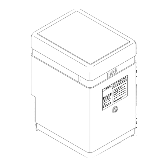
The LP1000 cover is 24" high and is removed by lifting it vertically off the operator. THE SITE FOR 104883 THE OPERATOR SHOULD BE CHOSEN WITH AT LEAST 24"... -
Page 7: Attaching The Chain Bracket
NOTICE: The Installer is responsible for guarding the post mounted Idler Sprocket in back drive installations. The chain brackets provided with the LP1000 operator should be mounted on the the gate with the centerline of the slot 8" above the top of the operator pad. -
Page 8: Placing The Vehicle Detector Loops
DETECTORS, Page 10.) PEDESTRIAN ACCESS MUST BE INSTALLED. The LP1000 provides for the use of two loop systems: 1) A "reversing" loop that will prevent the gate from closing on a vehicle that has stopped in the path of the gate and, 2) A "free exit" loop that will open so that the loops may be properly phased. -
Page 9: Section C: Installing The Operator
Very small standard screw driver. (For adjusting UNPACKING CHECKLIST The following is a check list of the various parts included with the LP1000 operator: 1 LP1000 Slide Gate Operator w/Cover 1 Chain Take-up Bolt Kit 2 Cover Lock Keys... -
Page 10: Accessory Equipment Hookup
WIRING REVERSING VEHICLE DETECTORS W A R N I N G ! Place the detector on the bottom plate of the LP1000 frame or in a remote electrical box, NEVER in the control box. Hook-up the power and loop wires on the detector harness according to the manufacturer's TO REDUCE THE RISK OF DAMAGE DUE TO instructions. -
Page 11: Bi-Parting Application
BI-PARTING APPLICATION connection). This is necessary as the LP1000 control board 24 VAC is In a bi-parting application, two operators are required, one operating isolated from chassis ground. -
Page 12: Left Or Right Hand Installations
BI-PARTING WIRING: PRIMARY/SECONDARY UNITS LEFT- OR RIGHT-HAND INSTALLATIONS 107033 The LP1000 operator can be configured for left- or right-hand gate installations. See Figure 16. On a normal drive installation, when standing inside the gate and facing outwards, if the operator is on the right side of the gate, it's a right-hand installation. -
Page 13: Setting The Limit Switches
D: STARTING THE OPERATOR W A R N I N G ! THE MOTOR WIRE CONNECTOR AND THE LIMIT HARNESS CONNECTOR MUST BOTH ALWAYS BE IN EITHER THE RIGHT OR LEFT POSITIONS. IF ONE IS IN THE RIGHT POSITION AND THE OTHER IN THE LEFT POSITION, THE OPERATOR WILL NOT STOP THE GATE WHEN IT REACHES THE END OF TRAVEL. -
Page 14: Section D: Starting The Operator
SETTING THE SWITCH SELECTABLE OPTIONS AUTOCLOSE TIMER ADJUSTMENT There are three (3) option selection switches on the LP1000 controller board that result in four (4) switch selectable options. Please review Figure 20. The switches are contained in a 3-pole dip switch package at the bottom right of the board. -
Page 15: Indicator Lamps
CHECKING THE INDICATOR LIGHTS as long as the wire is held on the terminal and the goes OUT when the wire is removed. There are 16 indicator lights on the control board of the LP1000 operator. See Figure 22. These lights are used to verify proper Connect to Terminal #7, Close.: Observe that the Motor Close... -
Page 16: Final Setting Of Limit Switches
IF THE INDICATOR TEST PERFORMED SATISFACTORILY, gate to a fully open or closed position or turn off and restore the power TURN OFF THE AC POWER SWITCH AT THE LP1000 to the operator. CONTROL BOX AND RECONNECT THE WHITE HIGH... -
Page 17: Terminal Strip Reference Chart
The LP1000 is equipped with a Self adjusting MAximum Run Timer, and re-entered to be recognized. SMART™, that will turn the LP1000 OFF if a Limit Switch command is not received within a few seconds of the time required to fully Open This input is used for “COMMAND OPEN/COMMAND CLOSE”... - Page 18 : STARTING THE OPERATOR TERMINAL STRIP REFERENCE CHART DESCRIPTION DESCRIPTION NAME NAME Momentary or continuous signal. On/ CLOSE Momentary or continuous signal. 12 OPEN EDGE Off mode set by Switch #1 This input is active only when referenced to the opening direction, WITH SWITCH 1 OFF: Once activated the gate will close fully.
-
Page 19: Wiring Diagram
: STARTING THE OPERATOR... -
Page 20: Section E: Auxiliary Equipment
Do not desired per the chart on page 17 and 18. connect to the terminal strip of the LP1000 at this time. Test the vehicle detector independently using the presence lamp on the front panel of the... -
Page 21: Safety Guide For The End User
To minimize the risk of entrapment in your gate system, install the following safety features: Thank you for choosing an Allstar product. We are confident you Electric gate edges will have many years of use and satisfaction with your gate operator. - Page 22 END USER INSTRUCTIONS GATE OPENER OPERATION AND SAFETY GUIDE AVOID ENTRAPMENT: Stay away from the path of the gate PREVENT PERSONAL INJURY OR DEATH: Do not stand and all moving parts (gate arms, etc.) at all times. Keep clear of the near or on the gate.
-
Page 23: Leader Exploded View & Parts List
OPERATOR EXPLODED VIEW 110153 WARNING! RISK OF ELECTROCUTION TURN OFF THE MAIN POWER SWITCH BEFORE ATTEMPTING SERVICE OR ADJUSTMENTS. OPERATOR PARTS LIST ITEM PART DESCRIPTION ITEM PART DESCRIPTION 010432 Cover, Leader Plus (Not Shown) 1 EA 106430 Bolt, 5/8-18 x 4L 2 EA 111814 V-Belt, 4L310... -
Page 24: Technical Specifications
Manufacturer’s Limited Warranty Allstar warrants its gate operators to be free from defect in material and workmanship for a period of five (5) years from the date of purchase for single family home use and three (3) years from the date of purchase for multi-family and commercial use. This warranty covers all components except the electronic circuit boards which are warranted for three (3) years from the date of purchase for single family home use and two (2) years from the date of purchase for multi-family and commercial use.
Need help?
Do you have a question about the LP1000 and is the answer not in the manual?
Questions and answers