Advertisement
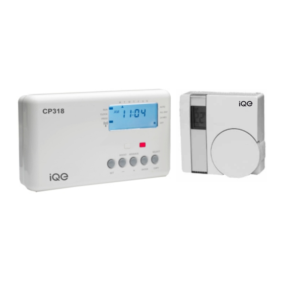
CP318
INSTALLATION INSTRUCTIONS
Combined Time Control and Room Thermostat
The CP318 combined wireless room stat and timeswitch allows a
combi boiler system to have a room thermostat added without the
need for any additional wiring.
Replacing the existing timeswitch with the CP318 will allow the
room thermostat to be connected wirelessly producing immediate
energy savings in houses where no previous room thermostat
has been fitted.
The device is intended to upgrade existing combi boiler systems
that do not have an existing room thermostat. It is not intended for
new installations where it will be necessary to install two heating
zones in order to comply with current Building Regulations.
1
Advertisement
Table of Contents

Related Manuals for iQe CP318


Summary of Contents for iQe CP318
-
Page 1: Installation Instructions
CP318 INSTALLATION INSTRUCTIONS Combined Time Control and Room Thermostat The CP318 combined wireless room stat and timeswitch allows a combi boiler system to have a room thermostat added without the need for any additional wiring. Replacing the existing timeswitch with the CP318 will allow the... -
Page 2: For The Installer
IEE wiring regulations. WARNING: Isolate mains supply before commencing installation. An example circuit diagram for a typical combi boiler installation is shown below. This diagram is schematic and should be used for guidance only. CP318 Timeswitch... - Page 3 The backplate may be fitted directly onto a single gang steel flush wiring box complying with BS4662, using two M3.5 screws. The CP318 is suitable for mounting on a flat surface only; they must not be positioned on a surface mounted wall box or on unearthed...
- Page 4 Recommended cable sizes are 1.00 or 1.5mm2 The CP318 is double insulated and does not require an earth connection but an earth connection is provided on the backplate for terminating cable earth connectors.
- Page 5 Tighten the two captive retaining screws to fix the unit securely. End view of CP318 timer Then switch on the mains supply. On completion of the installation please reset the timeswitch as...
-
Page 6: General Information
Resetting the timeswitch On the CP318 press the SET and SELECT buttons together. Then release the buttons and the timeswitch will return to preset factory settings. SELECT The preset factory settings are illustrated on page 12 of the USER GUIDE. -
Page 7: Room Thermostat
Room Thermostat Installation and pairing instructions The wireless electronic battery powered room thermostat uses interoperable two- way RF mesh networking technology to provide optimum comfort with close control of the energy used to heat the home without the need for additional wiring or unsightly cable runs. - Page 8 There is no ‘click’ from the thermostat which is silent in operation but there will be an audible ‘click’ from the CP318 when it is ‘On’ and the thermostat switches On and Off. 8) When the thermostat is calling for heat a flame symbol will appear in its display.
- Page 9 Stage 1A – Only used if ‘L’ is displayed instead of ‘I’ 1) Turn the dial of the thermostat until the letter P appears in the display. 2) Press the dial twice and PP should appear in the display. 3) Turn the dial until the letter ‘I’ appears in the display and return to the main instruction.
- Page 10 DIL switch settings – TPI temperature control software Thermostats using TPI (Time SWITCH CONFIGURATION CP318 Proportional Integral) control a l g o r i t h m s w i l l r e d u c e t h e...
- Page 11 Avoid installing the thermostat against or behind any large metal surfaces which could interfere with the radio signals to and from the CP318 timer with combined receiver. The thermostat should be mounted on an internal wall approximately 1.5 metres from floor level using the wall plate provided and should be in a position away from draughts, direct heat and sunlight.
- Page 12 Before fixing the wall plate in position check to see that the thermostat and boiler are still able to communicate satisfactorily by turning the thermostat temperature up and down to switch the boiler on and off. Offer the plate to the wall in the position where the thermostat is to be mounted and mark the fixing positions through the slots in the wall plate.
- Page 13 Timeswitch specification Contact Rating 3 (1) Amps 230V AC Contact Type Micro-disconnection changeover Voltage free Supply 230V AC 50Hz only Pollution Degree 2 Class A Software Type 1 Control Operating Temperature Range 0°C to +40°C Battery Life 10 months continuous operation (minimum) Case Material Thermoplastic, flame retardant...
- Page 14 Dimensions 86mm x 86mm x36.25mm Pollution control Degree2 Design standard EN60730 - 2-9 Temperature range 5°C – 30°C Enclosure protection IP30 Operating temperature range 0-40°C Case material Thermoplastic flame retardant www.iQE.co.uk Trade House BA22 8RT Leaflet number P85496 Issue 1...
Need help?
Do you have a question about the CP318 and is the answer not in the manual?
Questions and answers