
Related Manuals for iQe RT021


Summary of Contents for iQe RT021
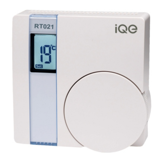
- Page 1 RT021 User and Installation Instructions Battery Operated Electronic Room Thermostat with TPI Temperature Control Software...
- Page 3 The RT021 will only operate when 2 x AAA batteries have been fitted and the thermostat is wired into your central heating system.
-
Page 4: For The User
FOR THE USER What is a room thermostat? ... an explanation for householders A room thermostat simply switches the heating system on and off as necessary. It works by sensing the air temperature, switching on the heating when the air temperature falls below the thermostat setting, and switching it off once this set temperature has been reached. - Page 5 The way to set and use your room thermostat is to find the lowest temperature setting that you are comfortable with, and then leave it alone to do its job. The best way to do this is to set the room thermostat to a low temperature - say 18°C - and then turn it up by one degree each day until you are comfortable with the temperature.
-
Page 6: Additional User Information
Nearby electric fires, televisions, wall or table lamps may prevent the thermostat from working properly. ADDITIONAL USER INFORMATION RT021 thermostat uses the latest control technology to provide extremely accurate temperature control which will help to keep your energy usage as low as possible without affecting your comfort levels. -
Page 7: User Instructions
USER INSTRUCTIONS The display will show the required temperature setting and can be adjusted in increments of 1°C. To adjust the required temperature setting turn the dial anti clockwise to decrease it and clockwise to increase it. When the thermostat is in the ‘call for heat’ condition a flame symbol will appear in the display. - Page 8 Battery Replacement RT021 runs on 2 x type AAA (Alkaline) non rechargeable batteries and is designed to give a battery life of approximately two years. When the batteries are nearing the end of their life a low battery symbol will appear in the display and the batteries should be changed within a few days.
- Page 9 N.B. The wall plate must not be altered or modified as it has been specially designed to isolate the mains supply when the thermostat is removed to change the batteries. Remove the old batteries and replace them with two new AAA size alkaline batteries ensuring that they are fitted correctly as indicated by the terminal markings in the battery compartments.
-
Page 10: Installation Instructions
Positioning the Room Thermostat RT021 should be mounted on an internal wall approximately 1.5 metres from floor level and should be in a position away from draughts, direct heat and sunlight. Ensure that there will be enough space to allow easy access to the two retaining screws located at the base of the wall plate. - Page 11 Once the wall plate has been removed from the packaging please ensure the RT021 is re-sealed to prevent damage from dust, debris etc. The wall plate should be fitted with the wiring terminals located at the top and in a position which allows a total clearance of at least 50mm around the RT021 thermostat.
- Page 12 Direct Wall Mounting Offer the plate to the wall in the position the RT021 is to be mounted and mark the fixing positions through the slots in the wall plate. Drill and plug the wall, then secure the plate in position. The slots in the wall plate will compensate for any misalignment of the fixings.
- Page 13 The wall plate is provided with a terminal guard to protect the user when replacing the batteries. This is supplied with the wall plate and it is essential that the terminal guard is fitted after completing the electrical connections to the terminals of the wall plate.
- Page 14 Ensure that no conductors are left protruding outside the central space enclosed by the wall plate. RT021 has voltage free contacts. Ÿ The RT021 is battery powered, therefore no mains Ÿ connection is required to power it. Please ensure that all RT021...
- Page 15 Typical combination boiler installation for boiler with built in timer and external room ‘stat RT021 terminal connections MAINS SUPPLY REMOVE LINK IF FITTED COMBINATION BOILER TERMINALS This diagram is schematic and should be used for guidance only.
- Page 16 Typical combination boiler installation with HP011 time switch and RT021 room thermostat HP011 TERMINALS TERMINALS L-5 SHOULD NOT BE LINKED MAINS SUPPLY RT021 For precise terminal ROOM connection information STAT please refer to boiler manufacturer’s instructions REMOVE LINK IF FITTED...
- Page 17 Fully Pumped Heating System using RT021 room stat, cylinder stat and Three Port Mid Position Valve with a HP021/HP027 electronic programmer. RT021 ROOM MAINS STAT SUPPLY FROST STAT IF STAT FITTED MRG POSITION VALVE PUMP & BOILER This diagram is schematic and should be used for...
- Page 18 ZONE ZONE VALVE VALVE PUMP & BOILER INSTALLATION AND CONNECTION OF THE RT021 MUST BE CARRIED OUT BY A SUITABLY QUALIFIED PERSON. WARNING: ISOLATE MAINS SUPPLY BEFORE COMMENCING INSTALLATION. This diagram is schematic and should be used for guidance only.
- Page 19 Ensure that the electricity supply to the RT021 is switched OFF. Swing the thermostat into position on the wall plate without fitting the battery terminal guard. Tighten the 2...
- Page 20 Now switch ON the electrical circuit to the RT021 and observe that it switches the heating system On and Off as the temperature is turned up and down on the thermostat. If the thermostat is switching the heating system satisfactorily then switch the electricity supply...
- Page 21 DIL Switch Settings – TPI Temperature Control Software Thermostats using TPI (Time Proportional Integral) control algorithms will reduce the temperature swing that normally occurs when using traditional bellows or thermally operated thermostats. As a consequence, a TPI regulating thermostat will maintain the comfort level far more efficiently than any traditional thermostat.
-
Page 22: Default Setting
For Gas boilers set the TPI setting to 6 cycles per hour. Ÿ (Default setting) Ÿ For Oil boilers set the TPI setting to 3 cycles per hour. Ÿ For Electric heating set the TPI setting to 12 cycles per Ÿ hour. SWITCH CONFIGURATION RT021 Switch positions for different TPI settings. - Page 23 Thermostat Specification Power Supply 2 x AAA alkaline batteries Contact rating 3 (1)amp at 230v AC Temperature accuracy +/- 0.5°C Contact type Micro disconnection Volt free changeover Dimensions 86mm x 86mm x 36.25mm Pollution control Degree2 Design standard EN60730 – 2-9 Temperature range 5-30°C Rated Impulse voltage...
- Page 24 Trade House BA22 8RT Leaflet number P85421 Issue 1...
Need help?
Do you have a question about the RT021 and is the answer not in the manual?
Questions and answers