DAITEM SC901AU Installation Manual
Hide thumbs
Also See for SC901AU:
- User manual (36 pages) ,
- Installation manual (68 pages) ,
- Installation manual (65 pages)

Related Manuals for DAITEM SC901AU


Summary of Contents for DAITEM SC901AU
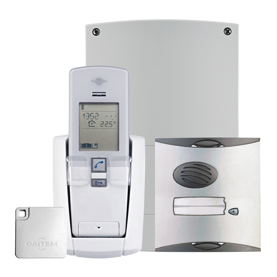
- Page 1 Installation guide Doorphone SC901AU / SC902AU SC100AU SC200AU / SC201AU MHF01X / MHF02X MHF03X / MHF04X MHF05X / MHF06X...
- Page 2 This manual describes how to install the following products: SC901AU Mains/mains code-operated 1-home doorphone kit SC902AU Lithium/mains 1-button 1-home doorphone kit SC100AU Interior handset unit + base + EU power pack SC200AU Mains controller SC201AU Lithium battery-operated controller MHF01X Translucent 2-home outdoor caller unit...
-
Page 3: Table Of Contents
Contents 1. Introduction..........................4 2. Description..........................6 2.1 Outdoor system ........................6 2.2 Interior handset unit ....................... 6 3. Tooling required ........................10 4. Preparation ..........................11 4.1 Guarantee stickers....................... 11 4.2 Charging the handset before installation ................12 5. Installing the outdoor system ....................15 5.1 Installing the outdoor caller unit .................. -
Page 4: Introduction
1. Introduction DOORPHONE SYSTEM COMPONENTS Outdoor caller units wired to main controller (road side) 1 call button 2 call buttons + tag reader + tag reader OUTDOOR SYSTEM 1 call button with keypad 2 call buttons with keypad + tag reader + tag reader Connection of gate motorisation system... - Page 5 Each kit comprises the following (minimum): • An outdoor caller unit installed on the road side, for visitors. • A controller installed on the same pillar but on the garden side. This controller provides: - the radio link with the interior handset unit, - the power supply to the outdoor caller unit and controller, - the connections to the electrical lock or latch and gate motorisation system.
-
Page 6: Description
2. Description 2.1 Outdoor system 2.1.1 Outdoor caller units with armoured cover Loudspeaker Programming keypad for entering access code to allow pedestrians and cars to enter Call button (1 or 2 depending on model) 4 handsets max. Gate access control button per button Blank label Latch/side gate access... - Page 7 2.2.2 Handset unit IMPORTANT: when installing the system, the handset(s) must be charged on their base before they can be used. Cover closed Cover open Removable belt clip Loudspeaker Display Communication button Latch/side gate control Garage button control button Inter-handset communication button Lighting...
- Page 8 2.2.4 Display description Handset battery status Communication in progress Radio range flat no signal Missed call Handset in silent mode needs poor charging charging average recommended good fully charged excellent charging Indoor temperature Scrolling text zone: Temperature unit: - display of time - °C: Celsius - outdoor temperature - °F: Fahrenheit...
- Page 9 2.2.5 Handset display in standby mode (general information screen) Handset battery status Outdoor temperature The temperature displayed is Time measured at the first access point programmed. Indoor temperature The temperature displayed is the handset temperature. Garage status Gate, side gate and latch status Lighting status...
-
Page 10: Tooling Required
3. Tooling required 6/8 mm PZ 0 PZ 2 3 mm 6 mm 3.5 mm GUARANTEE The conditions according to which the guarantee and after sales service apply are described in the general price list and can be sent on request. Some after sales service products and accessories, such as: •... -
Page 11: Preparation
4. Preparation 4.1 Guarantee stickers Remove the pre-cut parts of the stickers and stick these to the extension request supplied. On the back of the caller unit On the handset MHF01X Coller sur certif A0831A04823 SCA100AF Coller sur certif A0831A04823 Inside the controller 1. -
Page 12: Charging The Handset Before Installation
4.2 Charging the handset before installation IMPORTANT: when installing the system, the handset(s) must be charged on the base before it/they can be used. 4.2.1 Handset on mains-powered base 1. Open the base. 2. Remove the 4 anti-slip pads. Œ... - Page 13 6. Thread the power cable into one of the 7. Unscrew the locking screw. guides at the back of the base. Pozidriv 0 Alternative guides 8. Screw it back into the same place hence 9. Close the base. locking the base in “table” position. Pozidriv 0 10.
- Page 14 12. Connect the power pack to the mains 13. Put the handset on the base. (220 V). The handset displays this message for 2 sec. Electrical shock hazard Then IN CHARGE if the battery is not sufficiently charged. IMPORTANT: the mains socket must remain accessible so that the power pack can be easily disconnected.
-
Page 15: Installing The Outdoor System
5. Installing the outdoor system 5.1 Installing the outdoor caller unit IMPORTANT: to ensure the outdoor caller unit remains watertight, never try to open it! 1. To ensure easy use, fix the unit at a height 2. Mark and drill the outdoor caller unit holes of 1.20 m. - Page 16 Mounting the outdoor caller units with armoured cover 145 mm 145 mm 145 mm 145 mm IMPORTANT: use the label supplied and TIP: you can carefully position it in the space provided. print the labels using the software (EtikPrint) available on the Daitem web site.
- Page 17 Pozidriv 2...
- Page 19 IMPORTANT: when the armoured cover is positioned on the unit, there should be a 1 mm clearance (use the shim for this purpose) between the pillar and armoured cover. Pozidriv 2...
-
Page 20: Installing The Controller
5.2 Installing the controller 1. Unscrew the locking screw from the 2. Following the installation rules below, bracket and then remove it. mark 3 fixing points and drill a hole in the pillar using a Ø 6 mm drill bit. Pozidriv 2 4 cm minimum... -
Page 21: Connecting The Equipment
3. Insert a washer and fix the bottom and 4. Hook the base on to the fixing bracket. then the top of the bracket. Fixing without a washer Œ Detach and dispose of unused washers Pozidriv 2 Fixing with a washer 5. - Page 22 • All terminal blocks can be unplugged to facilitate wiring. • The connections to be made are summarised on a label inside the controller cover. 3. Connecting the outdoor caller unit Connect the 4 outdoor caller unit wires to terminal blocks 15 to 18 on the controller. 15 16 17 18 15/Green: Data –...
- Page 23 5. Connecting a gate motorisation system Use a cable cross-section of 22 mm (telephone type wire) to connect the system. IMPORTANT: for the information 9 10 11 12 13 14 feedback to be properly managed, the position contact (ref. CP500 on the price list) must be wired before NC NO power-up and be in closed position...
-
Page 24: Powering The Controller
5.4 Controller power supply 1. Three types of power supply can be used. • Battery then connect IMPORTANT: 908-21X the battery battery must be installed by positioning for current-based applications. Connect the it on the rails battery supplied to the and sliding connector. - Page 25 • Solar panel IMPORTANT: 908-21X battery must be installed for current-based applications. Connect the battery supplied to the connector. 2. When powered, the outdoor caller unit lights up and beeps every 2 sec. The radio link creation LED also lights up red for 2 sec. If this is not the case, check that the controller’s batteries or external power supply are properly connected.
-
Page 26: Creating The Radio Link Between The Handset And The Controller
5.5 Creating the radio link between the handset and the controller IMPORTANT: each call button on the outdoor caller unit can be linked via radio with up to 4 handsets. 1. At this stage in the installation procedure, the handset should display: If this is not the case, the handset needs to be charged (see chapter on Charging the handset before installation) until the... - Page 27 Controller Handset unit Outdoor caller unit 6. Put the controller in radio link creation mode by pressing The radio link creation LED lights up orange. 7. The radio link creation LED The handset displays: lights up orange. 8. Press once on the outdoor caller unit call button so that it calls the handset.
- Page 28 Controller Handset unit Outdoor caller unit 9. The handset displays: then Display of time, indoor and outdoor The radio link LED lights up temperature, gate, side gate and green for 2 sec. latch status (if position contacts connected). beeps for 2 sec The outdoor caller unit beeps for 2 sec.
-
Page 29: Testing The Radio Range
6. Testing the radio range Before installing the handset base, make sure the radio range between the handset and the controller(s) is good. 1. Stand in the place you wish to install the handset unit and quickly press the key. 2. -
Page 30: Installing The Interior Handset Unit
7. Installing the interior handset unit 7.1 On a table The table mounting procedure is described in the chapter on Charging the handset unit before installation. 7.2 On a wall This chapter describes how to move the handset unit from a “table” position (in which the handset unit is normally placed at this stage in the installation, see chapter on Charging the handset unit before installation) to a “wall”... - Page 31 4. Unscrew the base locking screw. 5. Open the base. Œ Pozidriv 2 6. Unscrew the locking screw. 7. Insert the screw here and tighten it. Pozidriv 0 Pozidriv 0 8. Rotate the back of the base until it is in wall position.
- Page 32 9. Mark the 2 fixing points and then make a hole using a Ø 6 mm drill bit. roughly 1.5 m high 10. Check the power pack jack is in the right 11. Feed the power cable through one of the position.
- Page 33 14. Tighten the locking screw. 15. Connect the power pack to the mains (220 V). Electrical shock hazard Pozidriv 2 IMPORTANT: the mains socket must remain accessible so that the power pack can be easily disconnected. 16. Place the handset on the base. The handset beeps once.
-
Page 34: Testing Operation
8. Testing operation 8.1 Testing communication with each interior handset unit 1. Press on the outdoor caller unit call button. IMPORTANT If the handset being called is To confirm the call, the outdoor caller unit already: • communicating with another rings at regular intervals for 30 sec. -
Page 35: Testing Access Controls
8.2 Testing access controls IMPORTANT: to test the access controls, it is first necessary to register a tag or programme an access code on the outdoor caller unit (see User manual/Modifying outdoor caller unit operating options). Activate the outdoor Status display Latch access status caller unit on the handset (1) -
Page 36: Appendices
9. Appendices 9.1 General information about creating the radio link An OPTWIN installation is a home-control system in which all the doorphone products communicate with each other via a hardwired bus or radio. It comprises different types of products that can be classed according to their function at a given time T in the installation: •... - Page 37 Configuring an OPTWIN installation consists in: • Creating radio links between the different transmitter and receiver products to define who controls who and who sends information to whom. • Allocating a function to each radio link, e.g. when the Light button on the handset is pressed, this activates the lighting controlled by the output receiver for 5 minutes.
- Page 38 9.1.1 The controller is used as a transmitter Application examples By creating a radio link between a controller and an output receiver, the following applications can be set up: • gate opening can switch on lighting to facilitate night time access and gate closing can switch off lighting, •...
- Page 39 Controller Receiver 4. Select the event associated with the function. Using the keys and controller display Event N° Event name Comment Gate opening This event is displayed when the gate is opened. Gate closed This event is displayed when the gate closes, as long as limit switches have been wired.
- Page 40 Controller Receiver 5. Validate the procedure. Press The radio link creation LED lights up green for 2 sec. Otherwise, start the procedure again. The radio link has been created. IMPORTANT: if an error occurs, the radio link LED flashes red 3 times. The radio link creation process should be performed again in this case.
- Page 41 9.1.2 The handset is used as a transmitter Application examples By creating a radio link between the keys on the handset and an output receiver, the following applications can be set up: Radio link n° 1, Press once on the to open the garage door and press again to close.
- Page 42 Handset Receiver 2. Switch to radio link creation mode. 3. Select the function. Information available in the receiver product manual. 4. Select the key associated with the function. Press on the key. then Select a command from the following: GARAGE 1 LIGHT 1 GARAGE 2 LIGHT 2...
- Page 43 Handset Receiver 5. Validate the procedure. Press the handset displays: then beeps for 2 sec Garage or light icon displayed The radio link has been created. If an error occurs, It beeps 3 times Perform the radio the handset displays: and then link creation automatically...
- Page 44 9.1.3 The controller is used as a receiver Transmitter Controller 1. Switch to radio link creation mode. Information available in the transmitter product manual. 2. Switch to radio link creation mode. Press The radio link creation LED lights up orange. 3.
- Page 45 Transmitter Controller 4. Select the key or event associated with the function. 5. Validate the procedure. The radio link creation LED lights up orange. Otherwise, perform the procedure again. Information available in the transmitter product manual. The radio link has been created. IMPORTANT: if an error occurs, the radio link creation LED flashes red 3 times.
- Page 46 9.1.4 The handset is used as a receiver Transmitter Handset 1. Switch to radio link creation mode. Information available in the transmitter product manual. 2. Switch to radio link creation mode. Display the following screen using the keys...
- Page 47 Transmitter Handset 3. Select the function. Select one of the 9 ringing tones available using the keys The handset displays: then beeps every 2 sec 4. Select the key or event associated with the function. 5. Validate the procedure. Information available in the transmitter product manual.
- Page 48 9.1.5 Specific cases • Creating a radio link between a handset and several controllers or several outdoor caller unit call buttons. A handset can be associated with 4 different inputs. By creating a radio link between the handset and the controller (see chapter on Installing the doorphone), you have created radio link n° 1 (e.g.
- Page 49 Controller Handset Outdoor caller unit 2. Switch the handset to radio link creation mode. Display the following screen using the keys The radio link creation LED flashes orange. 3. Press once on the outdoor caller unit call button to call the handset.
- Page 50 Controller Handset Outdoor caller unit 4. The handset displays: then The radio link creation LED beeps for 2 sec. lights up green for 2 sec. The outdoor caller unit beeps for 2 sec. “ EEP” Display of time, indoor and outdoor temperature, gate, side gate or latch status (if position contacts connected).
- Page 51 IMPORTANT: each handset can be linked via radio with a maximum of 7 other handsets. handset handset 1. Switch the handset to radio link creation mode. Display the following screen using the keys 2. Switch to radio link creation mode. Display the following screen using the keys...
- Page 52 handset handset 3. Press 4. The handset displays: 4. The handset displays: then then beeps for 2 sec. beeps for 2 sec. The radio link has been created. If an error occurs, It beeps 3 times Perform the radio the handset displays: and then link creation automatically...
-
Page 53: Testing The Radio Link
9.2 Testing the radio links This function is used to test the radio links created between a handset and a controller. To do this, open the controller cover and proceed as follows: Handset Controller 1. Switch the handset to radio link test mode. Display the following screen using the keys 2. - Page 54 Handset Controller 3. Select the controller to be tested using the keys 4. Press again on The controller screen displays “1”. is linked via radio to the controller gate output. The controller screen displays “2”. is linked via radio to the controller side gate output.
-
Page 55: Deleting Radio Links And Returning To Factory Programming
9.3 Deleting radio links and returning to factory programming 9.3.1 Deleting a radio link between a controller and a handset This function is used to delete the radio links created between a controller and a handset. Controller Handset Outdoor caller unit 1. - Page 56 Controller Handset Outdoor caller unit The radio link creation LED flashes orange. 3. Press once on the outdoor caller unit call button to call the handset. 4. The handset displays: then The radio link creation LED lights up green for 2 sec. beeps for 2 sec.
- Page 57 9.3.2 Returning the handset and controller to factory programming This procedure is used to delete all the radio links and reset all handset and controller parameters to their factory value. 1. Switch the handset to radio link deletion mode. Display the following screen using the keys...
- Page 58 2. Press and hold until the screen displays OK The handset displays: then beeps for 2 sec. If an error occurs, It beeps 3 times Perform the radio the handset displays: and then link deletion automatically procedure again. returns to the general information screen.
-
Page 59: Changing The Batteries
10. Changing the batteries IMPORTANT - There is a risk of explosion if the battery/ies is/are not properly replaced. - Replace the flat battery/ies with the same type. - Do not expose the battery to excessive heat (e.g. a flame) and do not throw it in a fire. Dispose of flat batteries in the appropriate waste disposal containers. - Page 60 5. Replace it with a new one (ref. 908-21X) 6. Reposition the making sure to thread the connector battery enclosure through the hole in the enclosure. in the controller. Π7. Reconnect the battery. 8. Connect a new MPU01X battery. 9.
-
Page 61: In The Handset
10.2 In the handset When you change the controller batteries, it is also advisable to change the handset batteries. 1. Take the handset off its base and remove 2. Insert a flat screwdriver into the slot and the belt clip by pressing on one of its press to open the handset. -
Page 62: Questions - Answers
11. Questions - Answers Questions Answers Why can conversation be This can happen when you are at the radio reception limit. “broken” when using the The controller cuts off communication when you go beyond handset? this limit. You should move closer to the controller. What causes the interference This can happen when the handset is too close to another (Larsen effect, crackling, etc.) - Page 63 Questions Answers When a radio link is created between a handset and the controller, the position contact must be closed. If this was not the case when the link was created, it must be deleted and recreated (see Appendix/Deleting radio links and then Creating a radio link between a handset and several controllers or several outdoor caller unit call buttons).
-
Page 64: Technical Data
12. Technical data General data • Failsafe multi-frequency radio technology with a free field (1) range of up to 400 m, according to environmental and installation conditions • High-fidelity digital sound Outdoor caller unit data • External boxes made of polycarbonate •...
Need help?
Do you have a question about the SC901AU and is the answer not in the manual?
Questions and answers