Advertisement
Quick Links
Contents
➢
The external units
• The controller unit
➢
Installation of the DoorPhone
➢
➢
Installation of the caller unit
➢
Installation of the controller
➢
Installation of the indoor station
• With battery operated base
• With mains operated base
➢
Testing
➢
Adjusting the type and volume of ring tone
➢
Radio recognition (*)
➢
Programming the caller unit with keypad
➢
Adjusting the door control
➢
Adjusting the motorized gate control
Quick installation
What to do if...?
Technical specifications
(
) The products supplied in a kit function together as soon as you insert the
*
batteries. It is not necessary to carry out radio recognition for these products.
Any handsets purchased as an accessory to a kit or issued as replacements
will require radio recognition as described in the appendix.
89
90
92
92
92
92
93
95
95
96
97
99
99
100
101
101
102
102
103
104
GB
104
106
108
110
Advertisement

Related Manuals for DAITEM SC902


Summary of Contents for DAITEM SC902
-
Page 1: Table Of Contents
Contents Presentation Description ➢ The external units • External caller unit • The controller unit ➢ The indoor station Installation of the DoorPhone ➢ Installation rules ➢ Installation of the caller unit ➢ Installation of the controller ➢ Installation of the indoor station •... -
Page 2: Presentation
Presentation COMPOSITION OF A DOORPHONE ➊ ➋ ➌ requires as a minimum Indoor station 1 button ➌ caller unit 2 button caller unit 2 button 1 button caller unit base caller unit with with keypad handset keypad standard station (battery operated base) ➋... - Page 3 Presentation Every kit comprises as a minimum: ➊ A caller unit on the street side for visitors. ➋ A controller installed on the same pillar (garden side), ensuring: • the radio link with the indoor station • the powering by batteries of the caller unit and controller •...
-
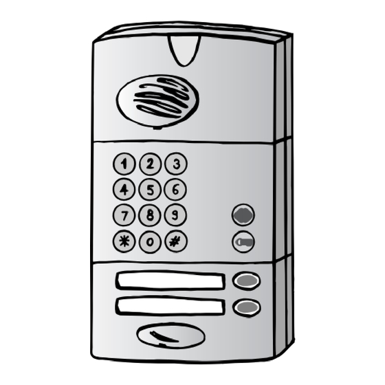
Page 4: Description
Description ➢ The outdoor units • The caller units Keypad for entry Screw cover of the access code preceding Loudspeaker the pedestrian and vehicle access commands Vehicle access Call button command (1 or 2 depending on model) button Personalised name label Pedestrian (label sheet supplied)* access... - Page 5 Description ➢ The indoor station (base) • Battery operated base Base unit underside Base unit cover Wall mounting bracket for internal operator unit (located on the underside Feet of the base unit) Captive screws to secure base unit cover (2 other screws on top) •...
-
Page 6: External Caller Unit
Description ➢ The indoor station (handset) • The handset (see user guide for more of details on the handsets keys) Telescopic antenna Loudspeaker Call button Display Control and setting buttons (according to model) Microphone NB: the battery cover is located at the rear of the handset Display Low batteries Indoor station base unit... -
Page 7: Installation Rules
Installing the DoorPhone ➢ Installation rules In order to ensure its weather-tightness: ➀ The technical controller must always be fitted antenna upwards. ➁ Ensure the antenna is tightened correctly. ➂ At the time of installing, always use the cable grommets. ➃... - Page 8 Installing the DoorPhone Required equipment • Drill and 6mm dia. Bit • If the cable goes through the pillar, drill and 8mm dia. bit minimum. • Philips or pozidrive no2 type screwdriver for mounting screws • 3.5mm dia. flat screwdriver for terminal block screws •...
- Page 9 Installing the DoorPhone ➢ Installing the controller So that it is easier to hook the base on the mounting bracket, choose a flat surface on the garden side pillar (or make it as flat as possible), especially for the top of the part. If necessary, use a wedge (not supplied) To remove the fixing bracket, unscrew the locking screw situated inside the controller.
-
Page 10: Appendices
Installing the DoorPhone Cut the cable to the Connect the 6 wires from required length. the external caller unit to 10 11 12 Pass the cable through terminals 7 to 12.* the cable grommet. Strip the ends of the wires. 7 (yellow) 8 (brown) 9 (grey) - Page 11 Installing the DoorPhone ➢ Installing the indoor station (battery operated base) The indoor station must be placed more than 2m away from the controller! For ease of use it is Mark the two wall bracket recommended the indoor mounting holes with a station be mounted 6mm dia.
- Page 12 Installing the DoorPhone ➢ Installing the indoor station (mains operated base) The indoor station must be placed more than 2m away from the controller! For ease of use it is Mark the two base recommended the indoor mounting holes with station be mounted a 6mm dia.
- Page 13 Installing the DoorPhone ➢ Functional Testing In the case of a system with several handsets, carry out this test with each indoor station. The handset sounds (“DING DONG” at regular gaps Press the call button for 30 seconds or as long as communication with the caller unit remains un-established) To confirm the call, the and the...
- Page 14 Appendix ➢ Radio recognition It is necessary for all handsets added to a kit or replacement handsets to undergo radio recognition! • Carry out the radio recognition using: - each of the handsets if the installation has several, - each of the buttons of the external caller unit if it has 2 call buttons, - each of the external caller units if the installation has two.
- Page 15 Appendix ➢ Programming the personal access code of the external caller unit with keypad A 4 or 6 digit access code must be programmed to facilitate the control of the lock and gate release. • Programming ✱ ✱ Long beep New personal Default Code access code...
- Page 16 Appendix Before making any connections disconnect one of the 4 batteries in the controller to avoid any risk of short circuit! ➢ Connection of an electric lock release or strike Pass the cables through cable entry grommets (see. diagram of the controller) Make connections as indicated on the diagram on the next page.
- Page 17 Appendix used door caller unit gate 1 2 3 4 5 6 7 8 9 10 11 12 13 14 15 16 17 18 look (1) manual motorised gate command position button contact (3) position contact (5) manual manual lock override command automatic gate...
-
Page 18: Quick Installation
Quick installation • External caller unit installation* • Controller installation 4 cm 12/White 7/Yellow 11/Pink 8/Brown 9/Grey 10/Green If necessary see radio recognition appendix... - Page 19 Quick installation • Battery operated indoor station installation Mains operated indoor station installation Screw the base Connect the to the wall transformer to the mains (230VAC) * for metal caller units, see the guide provided with the metal cover.
- Page 20 What to do if...? Problem Solution This can occur when interference is detected; it means the channel has What does a short noise in the handset mean? changed (Dynapass ® Technology) What does a continual noise This can occur at the edge of radio reception. in the handset mean? When beyond the limit, the call is cut off.
- Page 21 What to do if...? Problem Solution ◗ Check that vegetation doesn't obscure the antenna of the technical controller, if necessary clear it and spread it out. ◗ Try unfolding the handsets antenna to see if an improvement occurs. ◗ Connect a 2.5 m length of telephone type cable to terminal 6 of the controller.
-
Page 22: Technical Specifications
Technical specifications General features • Dynapass ® Technology multifrequency ultra-reliable radio, up to 400m range in free field (1), (will vary according to environmental conditions and installation) (2) • Radio range up to 400m in free field (will vary according to environmental conditions and installation) •...
Need help?
Do you have a question about the SC902 and is the answer not in the manual?
Questions and answers