Table of Contents
Advertisement
DVD/CD RECEIVER
XV-DV282AP
XV-DV181
XV-DV180
XV-DV585K
XV-DV590K
THIS MANUAL IS APPLICABLE TO THE FOLLOWING MODEL(S) AND TYPE(S).
Model
Type
XV-DV282AP
LXJ
XV-DV181
LXJ
XV-DV180
LXJ
XV-DV585K
SXJ5
XV-DV590K
SXJ5
For details, refer to "Important Check Points for good servicing".
PIONEER CORPORATION
PIONEER ELECTRONICS (USA) INC. P.O. Box 1760, Long Beach, CA 90801-1760, U.S.A.
PIONEER EUROPE NV Haven 1087, Keetberglaan 1, 9120 Melsele, Belgium
PIONEER ELECTRONICS ASIACENTRE PTE. LTD. 253 Alexandra Road, #04-01, Singapore 159936
PIONEER CORPORATION
Power Requirement
AC 220 V to 240 V
AC 220 V to 240 V
AC 220 V to 240 V
AC 220 V to 240 V
AC 220 V to 240 V
4-1, Meguro 1-chome, Meguro-ku, Tokyo 153-8654, Japan
2009
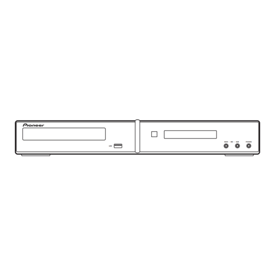
MAIN
MIC
SUB
PHONES
USB
XV-DV282AP
Region No.
T-ZZK MAY
ORDER NO.
RRV3936
Remarks
3
3
3
5
5
2009 Printed in Japan
Advertisement
Table of Contents
Troubleshooting

Related Manuals for Pioneer XV-DV282AP


Summary of Contents for Pioneer XV-DV282AP
- Page 1 PIONEER CORPORATION 4-1, Meguro 1-chome, Meguro-ku, Tokyo 153-8654, Japan PIONEER ELECTRONICS (USA) INC. P.O. Box 1760, Long Beach, CA 90801-1760, U.S.A. PIONEER EUROPE NV Haven 1087, Keetberglaan 1, 9120 Melsele, Belgium PIONEER ELECTRONICS ASIACENTRE PTE. LTD. 253 Alexandra Road, #04-01, Singapore 159936...
-
Page 2: Safety Information
LD ON mode in the test mode oscillates with the laser forcibly. 2. When the cover is open, close viewing through the objective lens with the naked eye will cause exposure to the laser beam. ∗ : See page 28. Name label XV-DV282AP... - Page 3 To protect products from damages or failures during transit, the shipping mode should be set or the shipping screws should be installed before shipment. Please be sure to follow this method especially if it is specified in this manual. XV-DV282AP...
-
Page 4: Table Of Contents
11. PCB CONNECTION DIAGRAM ............................80 11.1 09 DVDM and RHTS USB ASSYS..........................80 11.2 RHTS SYSMAIN ASSY...............................82 11.3 RHTS D-AMP ASSY ..............................86 11.4 RHTS DISPLAY ASSY ..............................88 11.5 POWER SUPPLY UNIT...............................90 11.6 EUROSCART ASSY ..............................92 12. PCB PARTS LIST ................................93 XV-DV282AP... -
Page 5: Service Precautions
Do not short-circuit between the plus speaker terminal and ground, such as the chassis, too. COMPONENT VIDEO LINE 1 CENTER FRONT VIDEO(TV) UNBAL 75 Ω AM LOOP HDMI OUT AC IN SURROUND WOOFER SPEAKERS (4 Ω ) ANALOG AUDIO IN VIDEO OUT Negative Speaker Terminal Do not short-circuit Ground (Chassis) XV-DV282AP... -
Page 6: When Replacing Dvd Deck
(1) Slide the rack, loading (White) toward the arrow direction by using a minus screwdriver to release the lock. (2) Manually open the tray. Note: Please strongly pushing rack, loading (White) to release the lock because the tray doesn't go out easily. Minus screwdriver Rack, loading (White) Tray open • Bottom view XV-DV282AP... -
Page 7: Specifications
Laboratories. “Dolby”, “Pro Logic” , and the double-D symbol are trademarks of Dolby FM antenna Laboratories. (ADH7030) Remote control ( XV-DV282AP, XV-DV585K, Manufactured under license under U.S. Patent XV-DV590K : XXD3185) #’s: 5,451,942; 5,956,674; 5,974,380; 5,978,762; ( XV-DV181, XV-DV180 AM loop antenna 6,487,535 &... -
Page 8: Panel Facilities
10 Character display Lights when the Extra Power mode/Front surround mode is selected. Lights when sleep timer is active. RPT and RPT -1 RPT lights during repeat play. RPT-1 lights 12 d during repeat one-track play. Lights during playback. XV-DV282AP... -
Page 9: Remote Control
MP3 EXP / V.ENH T.EDIT INPUT CHANNEL VOLUME MUTE Playback controls TV CONTROL buttons SHIFT VOLUME These control Pioneer flat screen TVs. 10 SHIFT 11 h OPEN/CLOSE 12 PLAYLIST buttons 13 MIC VOL +/– 14 MENU 15 RETURN 16 Tuner controls CLASS SHIFT+T.EDIT 17 MUTE 18 VOLUME +/–... -
Page 10: Basic Items For Service
Sound interrupted Mottled color Cleaning Before shipping out the product, be sure to clean the following positions by using the prescribed cleaning tools. Position to be cleaned Name Part No. Remarks Pickup lenses Cleaning liquid GEM1004 Cleaning paper GED-008 XV-DV282AP... -
Page 11: Pcb Locations
Parts marked by “NSP” are generally unavailable because they are not in our Master Spare Parts List. The > mark found on some component parts indicates the importance of the safety factor of the part. Therefore, when replacing, be sure to use parts of identical designation. LIST OF ASSEMBLIES XV-DV282AP XV-DV181 XV-DV180 XV-DV585K... -
Page 12: Jigs List
SDS1177 (SR/GRAY), SDS6050 (C/GREEN) Lubricants and Glues list Name Lubricants and Glues Remarks Daifree GEM1036 (ZLX-ME413A) Refer to "9.4 DVD MECHA ASSY" Refer to "9.4 DVD MECHA ASSY" Lubricating oil GYA1001 (ZLB-PN397B) Grease GEM1018 Refer to "9.4 DVD MECHA ASSY" XV-DV282AP... - Page 13 XV-DV282AP...
-
Page 14: Block Diagram
4. BLOCK DIAGRAM 4.1 OVERALL WIRING CONNECTION DIAGRAM BLUE TOOTH FM/AM TUNER UNIT u-COM DOWNLOAD (/LXJ:XXX3088) (/SXJ5:XXX3085) XV-DV282AP, XV-DV585K, XV-DV590K only /SXJ5 /LXJ /LXJ /SXJ5 CN2007 CN2003 96045-15C 9604S-11C IBD model 11P FFC (XDD3266) EU model 15P FFC TUNED 1/3,2/3,3/3 (XDD3306) 3.3V... - Page 15 ALRCK_CENTER GNDD GNDD ABCK_ARS ABCK_ARS JA4002 COMPOSITE XKB3069- GNDD GNDD VIDEO ACLK_LFE ACLK_LFE OUTPUT GNDD GNDD 23P FFC (XDD3302-) 17P FFC 19P FFC RHTS DISPLAY ASSY (XDD3305) (XDD3303) (/LXJ:XWM3485) (/SXJ5:XWM3486) 1/2,2/2 RHTS D-AMP ASSY UNIT (/LXJ:XWM3490) (/SXJ5:XWM3489) B2P-VH XDX3087- XV-DV282AP...
-
Page 16: Overall Block Diagram
Hi-side Y , C Y , C V+5USB V+5USB switch IC IC1103 FL DC +/- POWER SUPPLY UNIT VFDP SW 12V (from (10.5V) V+12(1 EV 3.3V VE+3 SW 5.0V POWER SW 6.8V SUPPLY V+6R8 SW 3.3V(B) V+3R3 SW 3.3V(A) XV-DV282AP... - Page 17 Blue : Control signal Note: ON SENSOR Green : Analog Audio Signal POWER LED XV-DV282AP, DV181, DV585K and DSP model only Black : Digital Audio Signal DV590K are non DSP model. Red : Voltage supply Orange : Video Signal PLAY...
-
Page 18: Dvd Loader/Decoder Block Diagram
4.3 DVD LOADER/DECODER BLOCK DIAGRAM XV-DV282AP... -
Page 19: Diagnosis
Assy. If the voltage is 0.4 V or higher, the 780-nm LD is degraded. 09 DVDM ASSY SIDE A How to turn on the LD Refer to “6.1 TEST MODE”. Q305 Q304 R154 R313 R326 C372 UP SIDE R322 C140 L308 Q307 CONTACT SIDE CONTACT CN102 CN104 SIDE XV-DV282AP... -
Page 20: Dvd Trouble Shooting
09 DVDM Assy displayed on the monitor Check the video signal path between DVD IC (09 DVDM Assy IC201) Video circuit after DVD IC (The FL display lights. The and video-out terminal (see the block diagram) (IC201) mechanism works.) XV-DV282AP... - Page 21 RGB video signal (IC401-pin 16, pin 18, pin 20) Check the waveform (ALCK: IC201-pin 231), (ALRCK: IC201-pin 227), No sound 09 DVDM Assy (ABCK : IC201-pin 230), (ASDATA0/1/2: IC201-pin 226/225/223). (Picture is normal) DVD IC (IC201) Check the waveform (ASPDIF: IC201-pin 215) XV-DV282AP...
-
Page 22: Circuit Description Of Digital Amp Section
SD_CD (pin 24) => L IC3401 OTW (pin 25) => L Output LPF section The carrier elements, high-frequency signals that are unnecessary for these speakers, are eliminated. The signals passed through the LPF will become sine-wave signals, as shown in the figure above. XV-DV282AP... -
Page 23: Specifications For The Protection Circuits For The Digital Amplifier
Conditions: The above prerequisite is upheld, and the conditions for an overcurrent detection are met. 5. Process when the protection circuits are activated The unit is shut down within 30 ms after abnormality detection then the volume level is set to 0. The unit can be turned on immediately after the shutdown. XV-DV282AP... -
Page 24: Error And Warning Message
ADAPTER PORT terminal sequence in BT AUDIO function ADP _DE T V P +5 ADP _DT I indefinite ADP _DT O About 1.5 second ADP _DE T logic In non-connection In connection ADAP T E R P OR T ADP _DE T XV-DV282AP... -
Page 25: Adapter Port Troubleshooting
Refer to the service manual (AS-BT100). signals output? Note: Outside factors such as setting of the Bluetooth device, affinity and radio waves environment may be causes. Refer to the block diagram and the circuit diagram, and confirm the signal path. XV-DV282AP... -
Page 26: Power On Sequence
6000 Start Over Temp Monitoring XOTW (78pin) 1260 6000 Key Mask 2080 SYS Mute ON DMUTECHECK (22pin) 2080 AMP Mute ON DSPMUTE (70pin) 5860 1300 Power Step STEP0^1 STEP1^2 STEP2^3 STEP3^4 STEP4^5 STEP5^6 STEP6^7 STEP7^8 1820 1940 2060 2080 XV-DV282AP... - Page 27 2600 2800 3000 3200 3400 3600 3800 4000 4200 4400 4600 4800 5000 5200 5400 5600 5800 6000 ation is sound is output st case in power on completion time. XV-DV282AP...
-
Page 28: Service Mode
: Press the [TEST] and [4] keys in order, and turn on the laser diode (780 nm). 3 Release the Test mode • Turn off the power. • Press the [ESC] key of the remote control unit and reset it. XV-DV282AP... -
Page 29: Display Specification Of The Test Mode
: [NTSC] PAL system : [PAL] Automatic setting : [AUTO] Scart terminal output [SK – * *] (Display only the WY model which can do the output setting of scart terminal.) VIDEO : [00] S-VIDEO : [01] : [02] XV-DV282AP... -
Page 30: Functional Specification Of The Shortcut Key
Region confirmation mode (ESC + A.MON [Test mode remote control unit] + "1"-"6" [Test mode remote control unit] keys) After you press the A.MON key while holding the ESC key pressed and then input the region number, if the number is different from that set in the unit, an error message is displayed, and the tray opens. XV-DV282AP... -
Page 31: Specification Of Model Information Display
Display it according to model information set from the FL controller. 2 Region No. 3 Part number 4 ROM version 5 Flash size 6 FL controller version 7 CHIP VERSION 9 Remote control code a Key code of Main unit XV-DV282AP... -
Page 32: Functional Specification Of The Service Mode
""e -2 : NG 7.0e -4 : NG 3 EDC/ID error history (ID Address, EDC/ID errors, last eight errors) Note: ∗ Error of AV1 is not supported in this player. Indication plan contents Character in bold : Item name : Information display XV-DV282AP... -
Page 33: Service Test Mode
V O L ∗ POWER OFF to get out from TEST MODE. ∗ When the TEST MODE is released, only the RAM which stores the error status will be initialized. (RAM that can be set by the user will not initialized.) XV-DV282AP... - Page 34 1. In the AMP ASSY, either one or more of the digital amp IC has broken down. 2. Short-circuit occurred somewhere between the faulty IC(s) and speaker terminal. 3. The XSD SHUTDOWN (71Pin) line has either short to ground or disconnected somewhere between the faulty digital amp IC and system microP (AYW7271, AYW7270). XV-DV282AP...
- Page 35 • The accumulated power-on time basically cannot be cleared. 7. DSP Error Display (for models with DSP only) • During POWER ON, you can switch between DSP error display <=> Normal display when the SOUND key on the remote control is pressed. XV-DV282AP...
-
Page 36: Disassembly
Remove the bonnet by removing the nine screws. (1) Press the u STANDBY/ON button to turn on the power. (2) Press the h OPEN/CLOSE button to open the tray. (3) Remove the tray panel. XV-DV585K, XV-DV590K (4) Set the test disc. Only Test disc Tray panel XV-DV282AP... - Page 37 (1) Slide the rack, loading (White) toward the arrow direction by using a minus screwdriver to release the lock. (2) Manually open the tray. Note: Please strongly pushing rack, loading (White) to release the lock because the tray doesn't go out easily. Minus screwdriver Rack, loading (White) Tray open • Bottom view XV-DV282AP...
- Page 38 (2) Unhook the five hooks. • Bottom view (3) Remove the front panel section. Front panel section Note A: Do not use an electric screwdriver. If the screw is over-tightened, the screw threads may be damaged. • Bottom view XV-DV282AP...
- Page 39 (open). Pickup PCB • Rear view (2) Disconnect the three flexible cables. CN966 CN964 CN965 • Rear view 09 DVDM Assy (3) Remove the four screws. (BBZ30P080FNI) (4) Remove the DVD MECHA Assy. DVD MECHA Assy XV-DV282AP...
- Page 40 Flexible cable for PICKUP Length: 15 mm Flexible cable Length: 50 mm • Bottom view • Bottom view Double side tape (ZTB-500-10) Length: 20 mm Flexible cable for LOADING Flexible cable for FEED • Right view • Right view XV-DV282AP...
- Page 41 Loading Motor Insulator (R) LOADING MOTOR PCB Assy TRAVERSE Assy • Screw Torque: 2.5 ± 0.3 kgf•cm (Screw 1) • Screw Torque: 1.0 ± 0.3 kgf•cm (Screw 2) • Screw Torque: 2.0 ± 0.3 kgf•cm Fig. 2-A Fig. 3-A XV-DV282AP...
- Page 42 3 supports 1. between A and B. Fig. 3-D 2. Remove the Plate Clamper, Magnet Clamper and Clamper. Check Hook Check Hook Plate Clamper Magnet Clamper Main Frame LOADING MOTOR PCB Assy Check Hook Fig. 3-E Clamper Fig. 5-A XV-DV282AP...
- Page 43 6. Remove the SW PCB Assy. 7. Remove the screw 4. 8. Remove the Gear Feed. 9. Remove the 2 screws 5. Safety surface for pressing of the insert. 10. Remove the Feed Motor. Fig. 7-C 11. Remove the Gear Motor. XV-DV282AP...
- Page 44 SW PCB Assy ~ FEED MOTOR ~ WHITE (4) BROWN (3) ~ SPINDLE MOTOR ~ YELLOW (2) GREEN (1) Fig. 7-D TRAVERSE Assy Check Hook • Loosen the wire in the direcion of the arrow. Fig. 7-E XV-DV282AP...
-
Page 45: Each Setting And Adjustment
ID number. 0 0 0 0 0 0 0 0 1 Note: If you press the PLAY button before inputting a 9-digit ID <PLAY> Enter number, the unit returns to Step 2 without doing anything else. Input ID Number ! XV-DV282AP... - Page 46 (The STOP key is not accepted after all 9 digits have been entered.) [Player's ID Number Setting] ID Number ? 0 0 0 0 0 0 0 0 1 Compare 0 0 0 0 0 0 0 0 1 <PLAY> Enter <STOP> Memory Clear Input ID Number ! XV-DV282AP...
- Page 47 (If the DVD DATA DISC has already been loaded, the unit does If the data cannot be read from the disc, the unit will be exited not start reading the data. In this case, open then close the ID Data Input Mode and proceed to the display of “Pioneer” tray.) logo.
-
Page 48: Exploded Views And Parts List
Screws adjacent to b mark on product are used for disassembly. For the applying amount of lubricants or glue, follow the instructions in this manual. (In the case of no amount instructions, apply as you think it appropriate.) 9.1 PACKING SECTION XV-DV282AP, XV-DV181, XV-DV180 Only XV-DV585K, XV-DV590K Only... - Page 49 15 Left Pad RHTS XHA3191 16 Right Pad RHTS XHA3190 17 Packing Case RHTS See Contrast table (2) (2) CONTRAST TABLE XV-DV282AP/LXJ, XV-DV181/LXJ, XV-DV180/LXJ, XV-DV585K/SXJ5 and XV-DV590K/SXJ5 are constructed the same except for the following: XV-DV282AP XV-DV181 XV-DV180 XV-DV585K XV-DV590K Mark No.
-
Page 50: Exterior Section
9.2 EXTERIOR SECTION XV-DV282AP, XV-DV181, XV-DV180 Only XV-DV585K, XV-DV590K Only Refer to “9.4 DVD MECHA ASSY.” XV-DV585K, XV-DV590K Only Refer to “9.3 FRONT SECTION.” XV-DV282AP... - Page 51 NSP 23 Guide Sheet XAK3603 24 Tray Panel RHTS XAK3653 NSP 25 Primary Barrier RHTS XAK3685 (2) CONTRAST TABLE XV-DV282AP/LXJ, XV-DV181/LXJ, XV-DV180/LXJ, XV-DV585K/SXJ5 and XV-DV590K/SXJ5 are constructed the same except for the following: XV-DV282AP XV-DV181 XV-DV180 XV-DV585K XV-DV590K Mark No.
-
Page 52: Front Panel Section
9.3 FRONT PANEL SECTION RHTS SYSMAIN CN4007 XV-DV585K, XV-DV590K Only XV-DV282AP... - Page 53 See Contrast table (2) 12 • • • • • 13 • • • • • 14 Screw BPZ30P080FNI (2) CONTRAST TABLE XV-DV282AP/LXJ, XV-DV181/LXJ, XV-DV180/LXJ, XV-DV585K/SXJ5 and XV-DV590K/SXJ5 are constructed the same except for the following: XV-DV282AP XV-DV181 XV-DV180 XV-DV585K XV-DV590K Mark No.
-
Page 54: Dvd Mecha Assy
09 DVDM Assy CN965 Do not replace the parts. Because, minute adjustments are needed if this condition is disassembled further more. If the repair is needed, replace the DVD MECHA Assy. Grease GEM1018 PCB640 09 DVDM Assy (SW PCB Assy) CN964 XV-DV282AP... - Page 55 30 Screw, Tap tite (P)(2.6 x 8) 811022680U 31 Screw, T-tite (B)(M1.7 x 5.0 P3) 813381750U 32 Screw, Pan (M1.7 x 2.3 P3) 814011723U 33 Screw, Tap tite (P)(2 x 8) 816112080U 34 Screw, Pan (M1.7 x 3 P3) 814011730U 35 Screw, Gear Feed 92P700007A XV-DV282AP...
-
Page 56: Schematic Diagram
V T H 1 0 5 4 - A V+3D GNDD V+5V GNDD (RF) : RF SIGNAL ROUTE V+3D : FOCUS SERVO LOOP LINE R 2 8 4 1 0 k : TRACKING SERVO LOOP LINE R 2 8 5 : STEPPING SERVO LOOP LINE GNDD GNDD XV-DV282AP... - Page 57 : VIDEO SIGNAL ROUTE (S_C) (R/Cr) : VIDEO SIGNAL ROUTE (R/Cr) R 6 2 8 (G/Y) SDATA : VIDEO SIGNAL ROUTE (G/Y) I C 6 0 1 (B/Cb) TC7SH08FUS1 : VIDEO SIGNAL ROUTE (B/Cb) (AD) GNDD : AUDIO DATA SIGNAL ROUTE GNDD XV-DV282AP...
-
Page 58: Dvdm Assy (2/2)
C 4 6 6 GNDD Y I N G N D 2 C 4 5 4 R_CR B I A S Y O U T C 4 5 5 G N D 1 Y S A G GNDD GNDD VIDEO XV-DV282AP... - Page 59 C 4 7 6 GNDD A-Side GNDD (C/V) : VIDEO SIGNAL ROUTE(C/V) (S_Y) : VIDEO SIGNAL ROUTE (S_Y) (S_C) : VIDEO SIGNAL ROUTE (S_C) : VIDEO SIGNAL ROUTE (R) : VIDEO SIGNAL ROUTE (G) : VIDEO SIGNAL ROUTE (B) XV-DV282AP...
-
Page 60: Rhts Sysmain Assy (1/3)
10.3 RHTS SYSMAIN ASSY (1/3) RHTS SYSMAIN ASSY (XV-DV282AP/LXJ:XWZ4426) (XV-DV181/LXJ:XWZ4454) (XV-DV180/LXJ:XWZ4425) (XV-DV585K/SXJ5:XWZ4434) (XV-DV590K/SXJ5:XWZ4435) SYSCOM SIMUKE Syscom ASEAN R1021(Kohm) R1022(Kohm) Model No. XV-DV180 XV-DV181 XV-DV282AP Assy No. XWM3496 XWM3520 XWM3497 &AW301 MODEL Syscom BASE BASE ST IC1002 (S-DV373) 4T/2T R1023(Kohm) N C 2... - Page 61 ALL Resistors are in k-k 2/3, 3/3 VE+3V V+3R3 V+3SUB RS1/16SS***J(1005 size) RS1/10SR****F(1608size) V + 3 V + 3 R 3 ALL Inductors are in uH V E + 3 V V + 3 S U B NM: No Mount XV-DV282AP...
-
Page 62: Rhts Sysmain Assy (2/3)
10.4 RHTS SYSMAIN ASSY (2/3) RHTS SYSMAIN ASSY (XV-DV282AP/LXJ:XWZ4426) (XV-DV181/LXJ:XWZ4454) V+3R3 (XV-DV180/LXJ:XWZ4425) C N 2 0 0 5 C N 2 0 0 4 X K M 3 0 0 8 - A (XV-DV585K/SXJ5:XWZ4434) X K M 3 0 0 4 - A... - Page 63 ALRCK V+3R3 L R C K M C D A T A D G N D S D T O MCDATA21 (pg3,to DVD) AK5358AET R 2 2 0 5 1 0 0 GNDD (AD) : AUDIO DATA SIGNAL ROUTE XV-DV282AP...
-
Page 64: Rhts Sysmain Assy (3/3)
10.5 RHTS SYSMAIN ASSY (3/3) RHTS SYSMAIN ASSY (XV-DV282AP/LXJ:XWZ4426) (XV-DV181/LXJ:XWZ4454) (XV-DV180/LXJ:XWZ4425) (XV-DV585K/SXJ5:XWZ4434) (XV-DV590K/SXJ5:XWZ4435) V E F 1 0 4 0 - A 1/3, 2/3 J H 4 0 0 1 HOTPLU SYSCOM SUB_SC *4 (BT) SUB_SD NOT for XV-DV180/XV-DV181 MODEL... - Page 65 585K, 590K GNDD GNDD C N 4 0 0 6 TO DVDMAIN ASSY V K N 1 2 4 8 - A LRCLK CN967 CN962 ASDAT1 EXCEPT XV-DV585, 590,30FS/YXJ5 TO DVDMAIN ASSY (Non DSP or Karaoke DSP model only) XV-DV282AP...
-
Page 66: Rhts Usb Assy
ALL Capacitors are in p-pF or uF unless otherwise specified Ratings Capacity(uF)/Voltage(V) Rated Voltage : 50V unless otherwise specified CH : CCSSCH(1005 size) (others : CKSSYB(1608size)) CEAL ALL Resistors are in k-k RS1/16SS***J(1005 size) RS1/10SR****F(1608size) ALL Inductors are in uH NM: No Mount XV-DV282AP... - Page 67 XV-DV282AP...
-
Page 68: Rhts D-Amp Assy (1/2)
GNDD GNDA VALID VBGAP CP144 XRST /RESET DVSS CP145 XHPSEL /HP_SEL /BKND_ERR CP146 CP15 XPDN /PDN DVDD CP147 XMUTE /MUTE DVSS R3104 V+3R3 DVDD DVSS DVSS VR_DIG R3105 17 18 29 30 X3101 CP149 CP150 ASS7062 13.5MHz R3106 GNDD XV-DV282AP... - Page 69 29 30 2125 size RS1/10S*** FROM POWER SUPPLY UNIT 3216 size RS1/8S*** 1608 size RS1/16S*** RS1/10SR*** GNDD capacitor 2125 size CKSQ*** 1608 size CCSR*** CKSR*** JQ: CEJQ***M** AL: CEAL***M** AT: CEAT***M** NM: No Mount (AD) : AUDIO DATA SIGNAL ROUTE XV-DV282AP...
-
Page 70: Rhts D-Amp Assy (2/2)
/SD_AB OUT_D C3311 R3311 R3302 /SD_CD PVDD_D R3301 0.1u/50 XOTW /OTW PVDD_D XOTW R3315 GREG BST_D 1.5(3216) GVDD V+BSW FL/RL (FL) AMPLIFIER GNDD LAYOUT NOTE : L325X L335X L345X are PCB track inductors approx. 50mm long and 1mm wide XV-DV282AP... - Page 71 R3441 C3441 330p/50 ATH7019 OUT_D R3403 ACN7148 /SD_AB OUT_D C3411 R3411 R3402 /SD_CD PVDD_D R3401 0.1u/50 /OTW PVDD_D XOTW R3415 1.5(3216) GREG BST_D GVDD V+BSW C/SW AMPLIFIER GNDD NOTICE R3211 to R3214,R3311 to R3314,R3411 to R3414 : ACN7148-(2.7Ω)(SUB:ACN7141-(2.7Ω)) (2W) XV-DV282AP...
-
Page 72: Rhts Display Assy
POWER ON OPEN /CLOSE GNDD ALL CAPACITORS ARE IN μF UNLESS OTHERWISE SPECIFIED CKSRYB***K** CCSRCH***J** JQ : CEJQ***M** AL : CEAL***M** AT : CEAT***M** ALL RESISTORS ARE IN Ω RS1/10SR***J ALL INDUCTORS ARE IN μH LAU***J-TA NM: No Mount XV-DV282AP... - Page 73 KARAOKE JQ-TS MODEL 30FS/YXJ5, C9005 (1/2) ONLY Q9000 (2/2) LSA1576UB(QR) R9003 L9001 (MAIN) R9008 3.3k CTF1306 R9015 XKN3018 6.8K C9010 R9020 82p/50 MCACC, NON- Q9001 XV-DV585, KARAOKE LTC124EUB MODEL C9011 ONLY FOR MCACC GNDD MODEL ONLY XV-DV585,585AP 590,595K,787, 787AP XV-DV282AP...
-
Page 74: Euroscart Assy
IC472 MM1507XN-TRB C473 CKS3388 CN461 GNDD C474 D474 DAN202U GNDD V+10 SQUEEZE R470 GNDD BLACK R471 Q462 (2/2) Q462 (1/2) RT3WLMM Q461 (1/2) RT3WLMM RT3WLMM R464 R462 4.7k 1.2k Q461 R463 (2/2) RT3WLMM Q472 Q463 4.7k RT1N241M RT1P441M GNDD XV-DV282AP... - Page 75 1000/6.3 R478 C492 GNDD NOTES ALL CAPACITORS ARE IN μF UNLESS OTHERWISE SPECIFIED CKSRYB**K50 JQ : CEJQ**M** AL : CEAL**M** AT : CEAT**M** ALL RESISTORS ARE IN Ω RS1/16S***J RS1/10S***J ALL INDUCTORS ARE IN μH LCYA***J2520 NM: No Mount XV-DV282AP...
-
Page 76: Power Supply Unit
10.11 POWER SUPPLY UNIT LIVE NEUTRAL XV-DV282AP... - Page 77 POWER SUPPLY UNIT (XWR3020) XV-DV282AP...
-
Page 78: Waveforms
Tray opening IC201 - pin 226, 225, 223 [ASDATA0/1/2] IC401 - pin 20 [CYOUT] V: 0.5 V/div. H: 10 μs/div. V: 1 V/div. H: 500 ns/div. It must be mesured by High-impedance probe. Playing DVD-REF-A1 Tr.2 Cp.19, Progressive output XV-DV282AP... - Page 79 RHTS D-AMP ASSY IC3201, IC3301, IC3401 [PWM_M, PWM_P] IC3201, IC3301, IC3401 [OUT_A, B, C, D] V: 1 V/div. H: 2 μsec/div. V: 5 V/div. H: 2 μsec/div. XV-DV282AP...
-
Page 80: Pcb Connection Diagram
Q307 R910 C140 L308 Q307 R911 CONTACT R919 SIDE R912 R913 R914 CONTACT C373 CN102 CN104 SIDE (ANP7686-A) CN953 RHTS USB ASSY CN5001 C5001 C5003 C5004 R5002 R5001 JA5001 XWZ4414 L5001 [[ G ]] A30C5/C7 F5001 R5003 R5004 (XNP3143-A) XV-DV282AP... - Page 81 R802 R151 C152 Q802 C151 C112 C111 R114 C102 R805 R111 R113 C101 R104 R101 R103 Q801 R304 CONTACT SIDE CN965 CN964 CN966 CONTACT SIDE CONTACT SIDE (ANP7686-A) CN965 CN964 LOADING MOTOR SW PCB RHTS USB ASSY XWZ4414 (XNP3143-A) XV-DV282AP...
-
Page 82: Rhts Sysmain Assy
Q1302 Q1303 Q1304 R1046 R1048 Q1104 Q1106 R1103 Q1102 Q1301 Q1307 C1112 Q1306 Q1308 Q1103 Q1202 L1102 Q1101 XWZ4 Q1201 Q1105 Q2002 IC1103 R1027 Q1203 R1056 R1008 IC1003 IC1003 R1014 R1016 JH4001 Q1204 R1015 R1017 R1020 R1025 C1008 R1026 C1013 XV-DV282AP... - Page 83 13.DEC_MUTE R1207 R1209 KN4201 Q1204 C4404 R1208 C4407 CN4007 C4401 C4403 R1017 0 1 2 3 0 1 2 3 4 5 6 7 8 9 R1020 R1025 C1008 R1026 C1013 L4402 L4401 R4401 R4403 CN4007 JP1002 (XNP3143-A) CN9401 XV-DV282AP...
- Page 84 SIDE B RHTS SYSMAIN ASSY UTEST11a STEST11a STEST11b UTEST11b (XNP3143-A) XV-DV282AP...
- Page 85 SIDE B 9.GND 7.GND 6.Cb 5.GND 4.Cr 3.GND 2.I/P 1.ASPECT 11.12.13.14.16.19.27.GNDD XV-DV282AP...
-
Page 86: Rhts D-Amp Assy
11.3 RHTS D-AMP ASSY SIDE A SIDE A RHTS D-AMP ASSY CN3201 (XNP3145-A) XV-DV282AP... - Page 87 SIDE B SIDE B RHTS D-AMP ASSY (XNP3145-A) XV-DV282AP...
-
Page 88: Rhts Display Assy
2.KEY2 3.REMOCON C9300 4.VE+3R3 W9008 UP SIDE 5.GNDD CONTACT 6.HP_R 15.FLCK 7.HPMUTE 16.FLDATA 8.GNDD 17.VFDP 9.HP_L 18.FLDC- DISPLAY ASSY 10.GNDD 19.GNDD 11.HP_DET 20.MIC [[ G ]] 12.V+12V 21.MIC BIAS 13.FLDC+ 22.MIC_DET C9402 14.FLCS 23.GNDD SIDE B RHTS DISPLAY ASSY XV-DV282AP... - Page 89 VOL UP S9306 S9300 STOP VOL DOWN S9304 S9301 C9006 S9302 S9303 C9013 9301 9301 W9013 IC9400 GNDD W9009 C9005 W9012 C9011 W9011 W9008 C9420 MAIN C9003 JA9100 MCACC JA9002 JA9001 V9400 W9003 VE+3R3 W9005 (XNP3144-B) SIDE B (XNP3144-B) XV-DV282AP...
-
Page 90: Power Supply Unit
11.5 POWER SUPPLY UNIT SIDE A SIDE A POWER SUPPLY ASSY XV-DV282AP... - Page 91 SIDE B SIDE B POWER SUPPLY ASSY XV-DV282AP...
-
Page 92: Euroscart Assy
11.6 EUROSCART ASSY SIDE A SIDE A EUROSCART ASSY W203 GNDD C471 GNDD C481 W103 VSEL2 W107 W108 W104 GNDD W101 C482 W202 GNDD W204 GNDD JA451 (ANP7569-B) SIDE B SIDE B EUROSCART ASSY Q462 (ANP7569-B) XV-DV282AP... -
Page 93: Pcb Parts List
Meaning of the figures and others in the parentheses in the parts list. Example) IC 301 is on the point (face A, 91 of x-axis, and 111 of y-axis) of the corresponding PC board. IC 301 (A, 91, 111) IC NJM2068V LIST OF ASSEMBLIES XV-DV282AP XV-DV181 XV-DV180 XV-DV585K XV-DV590K... - Page 94 R9501 Not used RS1/10SR680J R9502 Not used RS1/10SR560J C9501 Not used CKSRYB103K25 PCB PARTS LIST FOR XV-DV282AP/LXJ UNLESS OTHER WISE NOTED Mark No. Description Part No. Mark No. Description Part No. CN 962 13P CONNECTOR VKN1472 CN 963 31P CONNECTOR...
- Page 95 C 2109,2110 CCSSCH270J50 D 1001 RB751V-40 D 1201,1204,1205 1SS352 C 2111,2204,2206,4008 CKSSYB104K10 D 1202,1301 MC2846-11 C 2201 CEAT220M50 C 2203 CKSQYB225K10 MISCELLANEOUS C 2207 CKSRYB105K10 L 1101,1102 CHIP SOLID INDUCTOR ATL7002 C 2308,2316 CEAT470M35 L 4001 CHIP SOLID INDUCTOR QTL1013 XV-DV282AP...
- Page 96 R 2313 RS1/8SQ152J L 1101,1102 CHIP SOLID INDUCTOR ATL7002 R 4301-4304 RS1/8SQ75R0F L 4001 CHIP SOLID INDUCTOR QTL1013 Other Resistors RS1/16SS###J L 4401,4402 INDUCTOR CTF1346 JA 4002 JACK XKB3069 CAPACITORS JA 4003 CONNECTOR CKS5712 C 1001,2306 CCSSCH101J50 C 1002,1003,1005 CKSSYB103K16 XV-DV282AP...
- Page 97 R 3113 (A,78,117) RS1/10SR3R3J C 4013,4014 CCSSCH220J50 R 3114 (A,36,103) RS1/10SR103J C 4052,4053,4109,4110 CCSSCH221J50 R 3131 (A,113,109) RS1/10SR473J C 4111,4112 CEAT100M50 R 3132 (A,111,113) RS1/8SQ123J C 4302 CEAT102M6R3 R 3133 (A,112,106) RS1/10SR102J R 3134 (A,114,101) RS1/10SR222J R 3135 (A,116,101) RS1/10SR102J XV-DV282AP...
- Page 98 R 3317 (A,64,67) RS1/4SA1R5J R 3318 (A,78,67) RS1/4SA1R5J R 3913 (A,83,114) RS1/10SR472J R 3323 (A,55,93) RS1/8SQ821J R 3914 (A,84,110) RS1/10SR472J R 3324 (A,78,93) RS1/8SQ821J R 3915 (A,84,114) RS1/10SR472J R 3325 (A,53,93) RS1/8SQ821J R 3916 (A,83,110) RS1/10SR472J R 3921 (A,101,113) RS1/10SR8R2J XV-DV282AP...
- Page 99 C 3238 (A,45,32) CKSRYB103K50 C 3432 (A,110,46) CFTLA474J50 C 3239 (A,48,35) CKSRYB103K50 C 3433 (A,95,30) CKSRYB104K25 C 3240 (A,52,25) CKSRYB103K50 C 3434 (A,89,24) CKSRYB104K25 C 3241 (A,26,75) CKSRYB331K50 C 3435 (A,93,30) CKSRYB104K25 C 3242 (A,40,75) CKSRYB331K50 C 3436 (A,92,24) CKSRYB104K25 XV-DV282AP...
- Page 100 C 9403 (B,103,40) CCSRCH221J50 R 9002 (B,184,44) RS1/10SR332J R 9003 (B,193,30) RS1/10SR332J C 9404 (B,96,43) CCSRCH221J50 R 9004 (B,199,31) RS1/10SR332J C 9405 (B,92,45) CCSRCH221J50 C 9406 (B,123,47) CKSRYB103K50 R 9006 (B,184,40) RS1/10SR332J C 9407 (B,75,28) CKSRYB223K50 R 9008 (B,200,38) RS1/10SR473J XV-DV282AP...
- Page 101 R 493 (B,76,42) RS1/16S472J R 494 (B,76,40) RS1/16S472J R 495 (B,89,23) RS1/16S331J R 496 (B,85,23) RS1/16S331J CAPACITORS C 464 (B,66,65) CKSRYB104K50 C 470 (B,41,73) CKSRYB104K50 C 471 (A,35,57) CEAT100M50 C 472 (B,39,52) CKSRYB104K50 C 473 (B,24,57) CKSRYB104K50 C 474 (B,24,61) CKSRYB104K50 XV-DV282AP...
Need help?
Do you have a question about the XV-DV282AP and is the answer not in the manual?
Questions and answers