Table of Contents
Advertisement
Quick Links
Download this manual
See also:
Quick Manual
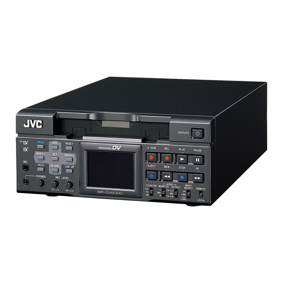
DV VIDEO CASSETTE RECORDER
DV VIDEOKASSETTENREKORDER
ENREGISTREUR A CASSETTE DIGITAL VIDEO
DV VIDEOREGISTRATORE
UNIDAD GRABADORA DE VÍDEO DV
BR-DV6000E
Thank you for purchasing this JVC product.
Before operating this unit, please read the
instructions carefully to unsure the best
possible performance.
MENU
RESET
DISP
Mini
PROFESSIONAL
SEARCH–
SET
SEARCH+
MIC
HOLD
BLANK
CUE UP
PHONES
REC LEVEL
BR-DV6000
CH-1/3
CH-2/4
INSTRUCTION MANUAL
BEDIENUNGSANLEITUNG
MODE D'EMPLOI
ISTRUZIONI PER L'USO
MANUAL DE INSTRUCCIONES
OPERATE
A.DUB
REC
PLAY
PAUSE
EJECT
REW
STOP
FF
AUDIO
INPUT
COUNTER
MONITOR OUTPUT
SELECT
REMOTE
CTL
L
CH-1/2
DV
TC
MIX
MIX
LINE
UB
R
CH-3/4
Y/C
LOCAL
(CPN)
LLT0034-002B-H
Advertisement
Table of Contents

Subscribe to Our Youtube Channel
Related Manuals for JVC BR-DV6000E


Summary of Contents for JVC BR-DV6000E
- Page 1 UNIDAD GRABADORA DE VÍDEO DV BR-DV6000E MENU Mini SEARCH– HOLD PHONES Thank you for purchasing this JVC product. Before operating this unit, please read the instructions carefully to unsure the best possible performance. INSTRUCTION MANUAL BEDIENUNGSANLEITUNG ISTRUZIONI PER L’USO MANUAL DE INSTRUCCIONES RESET A.DUB...
- Page 2 5 When the RM-G800 remote controller is used, the counter, etc. may malfunction due to inter- ference generated by the peripheral equipment. In this case, consult your nearest JVC dealer. Supplement...
-
Page 3: Safety Precautions
SAFETY PRECAUTIONS Warning Notice FOR YOUR SAFETY (Australia) 1. Insert this plug only into effectively earthed three-pin power outlet. 2. If any doubt exists regarding the earthing, consult a qualified electrician. 3. Extension cord, if used, must be three-core correctly wired. IMPORTANT (In the United Kingdom) Mains Supply (AC 230 V ` WARNING –... -
Page 4: Main Features
● Both NTSC and PAL signals supported Playing back NTSC tapes or recording NTSC signals from the DV input is possible on the BR-DV6000E. Please select NTSC on PB/DV IN menu. For analog signal input, only PAL is supported. -
Page 5: Table Of Contents
Presetting the time code ... 59 Recording the time code ... 60 Playing back the time code ... 63 EDIT Editing with an RS-422A/JVC bus edit remote controller ... 64 Using a non-linear editing system ... 68 MENU SCREENS Structure of the Menu screens ... 69 Setting the menus ... -
Page 6: Introduction Remarks Of Usage
INTRODUCTION Remarks of usage Place of storage and use Avoid storing or using this VCR in the following places: ● Excessively hot or cold places beyond the al- lowable temperature for operation (5˚C – 40˚C). ● Humid or dry places beyond the allowable humidity range for operation (30% –... -
Page 7: Regular Maintenance
For details, refer to page 100, “Checking the hour meter.” : For details on the maintenance plan and fee, consult with your JVC-authorized service agent. • If the head is dusty, “HEAD CLEANING RE- QUIRED!” will be displayed on the monitor when this unit plays a tape. -
Page 8: Cleaning Tape
5 hours Cassette tape BR-DV6000 can record onto and playback stan- dard DV and mini DV cassette tapes (for SP mode only). Use the following JVC cassettes with the logo. ● Standard DV cassettes ● Mini DV cassettes LA-DV276 M-DV63PRO... -
Page 9: Condensation
For recording and storing videotapes in the best condition Observe the following instructions for the best recording and storage of videotapes. • Take care of the conditions of handling videotapes. It is recommended that you record and store videotapes in the environment below. Temperature Humidity Hourly temperature change... -
Page 10: Names And Functions Of Parts
• OPERATE LED lights up as follows. Operate ON : the green LED lights up Operate OFF : the red LED lights up VCR error : the red LED blinks Memo ● If DC IN MODE in the SYSTEM MENU screen is set to “OPE ON”... -
Page 11: Stop Button
[PLAY] button/LED • Press this button to start playing back a tape. During playback, the green LED lights up. • When recording is paused, press this button to resume recording. • When audio dubbing is paused, press this button to resume audio dubbing. [PAUSE] button/LED •... - Page 12 The 9-PIN REMOTE 1 terminal can be selected using REMOTE SEL 9 PIN while the 12-PIN REMOTE 2 terminal can be selected with RE- MOTE SEL JVC. Memo ● To control BR-DV6000 with the SERIAL RE- MOTE terminal or DV terminal, this switch set-...
- Page 13 Memo ● For the MIX setting, noise is sometimes gen- erated. If it occurs, set it to CH-1/2 or CH-3/4. ● In the 48 K audio mode, it is fixed at chan- nels CH1 and CH2 regardless of the setting of the switch.
- Page 14 NAMES AND FUNCTIONS OF PARTS MENU DISP Mini SEARCH– HOLD BLANK PHONES REC LEVEL CH-1/3 [REC LEVEL] Volume for audio recording level for CH1/3 and CH2/4 Use the switch to adjust the audio recording level for CH1 and CH2. During audio dubbing, the audio recording level for CH3 and CH4 can be adjusted with this switch.
-
Page 15: Setting Screens
Special functions/Setting buttons The following buttons have different functions depending on whether the normal screen or the setting screen is displayed. Setting screens: Menu, Date/Time setting, Time code preset and Multi Cue-up [DISP/8] button • During normal display, this button is used to enable/disable the LCD or select display style. -
Page 16: Rear Panel
NAMES AND FUNCTIONS OF PARTS VIDEO LINE MONITOR SIGNAL DC12V [VIDEO LINE IN] terminal (BNC) This is the input terminal for composite video signals. • To input video via this terminal, set the IN- PUT SELECT switch located on the front panel to “LINE”. - Page 17 [SYNC IN] synchronization input terminal (BNC) This is the terminal for inputting reference syn- chronization signals from an external source. For external synchronization signals, input com- posite video signals of 1V (p-p) or lower (e.g., black burst signal). ☞ Page 29 “Synchronization signal”) [TIME CODE IN] terminal (BNC) This is the EBU-compliant time code input ter- minal.
- Page 18 NAMES AND FUNCTIONS OF PARTS VIDEO LINE MONITOR SYNC IN & SIGNAL DC12V DC power input terminal (2-PIN) This terminal is for inputting DC 12 V. Connect the DC power cord of the supplied AC adapter. Memo ● When power is supplied to this terminal, the OPERATE indicator located on the front panel lights up.
- Page 19 Consult your JVC authorized service agent for such replacements. › [REMOTE2] JVC Bus terminal (12-PIN) This terminal is for connecting to the JVC bus interface-compatible editing remote controller (RM-G800). With this terminal, BR-DV6000 can be used as a player or recorder of an editing system.
-
Page 20: On-Screen Display
REC LEVEL COUNTER BR-DV6000 CH-1/3 CH-2/4 LCD screen On-screen display Displays the setting status of the VCR Status display operation mode, date/time, counter. Displays the operating status of blank Event display search, index recording/search. Displays error/alarm messages for in- Alarm display correct operation or improper condi- tion of BR-DV6000. -
Page 21: Status Display
ON-SCREEN DISPLAY Status display: It displays the current settings and operating status. 3 2 K C H – 1 / 2 A S S E M W A R N I N G 7 0 0 1 D R UM MO T O R F A I L U R E R E C I N H I B I T S T A N D B Y - O F F 0 3 / 0 4 / 0 3... - Page 22 ON-SCREEN DISPLAY Item Counter display E-22 – Status display – (continued) 3 2 K C H – 1 / 2 A S S E M W A R N I N G 7 0 0 1 D R UM MO T O R F A I L U R E R E C I N H I B I T S T A N D B Y - O F F 0 3 / 0 4 / 0 3...
-
Page 23: Status/Event Display
1 1 : 2 0 : 0 0 T C R 0 2 : 0 0 : 0 0 : 0 0 Description Displays the VCR operation mode, including: PLAY, EJECT, FF, REW, STANDBY-ON, STANDBY-OFF, STILL, REC, REC PAUSE, A. DUB, A. DUB PAUSE, ASSEM EDIT, INSERT EDIT, SHTL (shuttle search), JOG, BLANK SRH (blank search), NO CASSETTE (cassette tape not loaded), OPERATE OFF. -
Page 24: Alarm Display
Disconnect the power and place it at a cool place. If this message is displayed again, BR-DV6000 could be defective. Consult your JVC-authorized service agent. ● “B” display : Messages for incorrect operation are displayed for about 3 seconds. They are displayed when the DISPLAY mode is ON or AUTO. - Page 25 Display A. DUB INHIBIT The user attempted to perform audio dubbing on a tape that is not ready for (REC TAB) recording (the rear switch is set to SAVE). A. DUB INHIBIT This message is displayed when audio dubbing is attempted under the following (48 K) conditions.
-
Page 26: Lcd Display
ON-SCREEN DISPLAY There are two display modes for the status display on the LCD of the unit. • Same character display mode as the monitor output • LCD display mode (enlarged display) DISPLAY button A.DUB MENU DISP RESET Mini PROFESSIONAL SEARCH–... - Page 27 .(dot): Drop frame. With PAL, this is fixed to F. 8 VCR mode display Displays the operation mode of the VCR. The reservation of mode is displayed in blinking light. NOCAS (no cassette tape), EJECT, STBON (standby- on), STBOF (standby-off), PLAY, STILL, FF, REW, SHTL,...
-
Page 28: Connection
CONNECTION Video output, e.g., VCR Input Composite Component VIDEO LINE MONITOR SYNC IN SIGNAL DC12V Composite Component Output Video output, e.g., VCR Output signal When BR-DV6000 enters the STOP, REC or EDIT mode, the input signal (E-E image) is out- put. - Page 29 Thus, input stable signals, e.g., those having gone through a TBC. ● A digital VCR requires that video signals for recording be delivered from a stable source. Video signals from an analog VCR must be run through a TBS or TBC.
-
Page 30: Connecting Audio Signals
CONNECTION Audio output of VCR Input COMPONENT VIDEO LINE MONITOR SYNC IN TIME CODE SERIAL TIMER SIGNAL IN/OUT DC12V REMOTE Analog audio (2 channels) Output Audio input of VCR Output signal When BR-DV6000 is in the STOP, REC or EDIT mode, signals (EE sound), which have been input, are output. -
Page 31: Digital Output
● Connecting to a monitor TV A monitor TV can be connected to the AUDIO MONITOR OUT terminal. The sound output from the AUDIO MONITOR OUT terminal is monaural. • The volume is adjusted through the monitor • The output channel can be selected with the AUDIO MONITOR switch on the front panel (Refer to the following table). -
Page 32: Connecting To Editing System
CONNECTION BR-DV6000 is equipped with 2 remote terminals, for the JVC bus and RS-422A for editing pur- poses. When a JVC bus-compatible editing remote controller is used: For the editing remote controller, use RM-G800. Example: BR-DV6000 as player and recorder for cut editing of digital signals. - Page 33 ● VHS/S-VHS VCR BR-S800 (equipped with SA-K26, SA-R50, SA-N50) BR-S822 (equipped with SA-T22) * No input/output of DV signals is possible. ● D-9 (digital S) VCR BR-D80, BR-D85, BR-D750 (Only analog signals) ● DV VCR BR-DV3000 (player only) BR-DV600/A (player only)
-
Page 34: Connecting With Serial Remote Terminals
Signal distributor Video Sound SERIAL ❈ Dubbing unit: VCR with SERIAL IN and OUT terminals DV: BR-DV6000 Memo If REPLICATION of the SYSTEM (2/2) Menu screen is set to DV, the REC command is output from the DV terminal. -
Page 35: Connecting The Ac Adapter
CONNECTION Connect the supplied AC adaptor to BR-DV6000. Supplied AC adaptor Supplied power cord OPERATE indicator OPERATE A.DUB PLAY PAUSE ONAL EJECT STOP AUDIO INPUT COUNTER MONITOR OUTPUT SELECT REMOTE CH-1/2 LINE CH-3/4 DV6000 LOCAL (CPN) Memo ● Even in the OPERATE OFF mode, a small amount of electricity will still flow into the unit. -
Page 36: Preparation
PREPARATION Turning on the power OPERATE indicator RESET A.DUB DISP PROFESSIONAL SEARCH+ EJECT BLANK CUE UP REC LEVEL COUNTER MONITOR OUTPUT BR-DV6000 CH-1/3 CH-2/4 Note After the OPERATE button is pressed and BR- DV6000 is turned on, if the green indicator blinks or the monitor or the LCD displays “UN- PLUG MAIN POWER, PLUG BACK IN AFTER A WHILE”, unplug the power cord from the... -
Page 37: Operation Method
Memo With the REMOTE/LOCAL switch set to REMOTE, the JVC bus or RS-422A can be enabled using REMOTE SEL JVC or RE- MOTE SEL 9P in the REMOTE (1/2) Menu screen. • The setting position of the REMOTE switch for operating BR- DV6000 with the SERIAL REMOTE terminal can be selected using REMOTE SEL SER in the REMOTE (1/2) Menu screen. -
Page 38: Loading/Ejecting Cassette
Ensure that no cassette tape is loaded. With no cassette tape loaded, the cassette LED is off. When no cassette tape is loaded, the status display for the VCR operation mode shows “NO CASSETTE” on the monitor or the LCD. -
Page 39: Setting The Lcd Display
PREPARATION DISP button MENU RESET A.DUB DISP Mini PROFESSIONAL SEARCH– SEARCH+ EJECT HOLD BLANK CUE UP PHONES REC LEVEL COUNTER M BR-DV6000 CH-1/3 CH-2/4 DISPLAY (2/2) Menu screen – – – D I S P L A Y [ 1 / 2 ] – – – L C D B R I G H T N E S S L C D C H R O M A L C D C O N T R A S T... -
Page 40: Setting/Displaying Date And Time
PREPARATION This function sets up the date and time of the built-in clock. With the built-in chargeable battery, the date and time data that have been set are maintained even after the main power is turned off. The set date and time data are displayed on the monitor or the LCD display according to the settings in the Menu screen. -
Page 41: On-Screen Status Display
– – – C L O C K A D J U S T – – – D A T E 0 3 / 0 4 / 0 3 T I M E 1 2 : 0 0 P A G E B A C K Selecting date/time display The date and time data can be displayed on the monitor or LCD on-screen display (status display). -
Page 42: Recording
RECORDING MENU RESET DISP Mini PROFESSIONAL SEARCH– SEARCH+ BLANK CUE UP HOLD PHONES REC LEVEL BR-DV6000 CH-1/3 CH-2/4 INPUT SELECT switch Selecting input signal Select the signal with the INPUT SELECT switch located on the front panel. : For inputting DV signals (video and audio) LINE : For inputting composite video and... -
Page 43: Recording Procedure
STOP mode can be set with LONG PAUSE TIME in the SYSTEM (1/2) Menu screen. ● When a home-use DV VCR is used to play tapes recorded with BR-DV6000, the sound level may be reduced. Recording index signals If INDEX WRITE is set to ON in the SYSTEM (2/2) Menu screen, an index signal is recorded at the recording starting position of the tape. -
Page 44: Audio Dubbing
(such as LP mode or 48 kHz audio mode), the VCR will enter the STOP mode. When this happens, loud noise from the DV output may come out. Hence, before audio- dubbing, check the recording mode of the tape. -
Page 45: Backup Recording Function
RECORDING In combination with DV equipment, BR-DV6000 can perform continuous, long-hour recording. BR-DV6000 can be set as the backup unit connected to a DV camcorder (GY-DV300/DV500/DV550/ DV5000, etc.). When the recording tape of the source unit nears its end, BR-DV6000 can start recording, enabling long-hour recording. -
Page 46: Recording With Serial Remote Terminals
RECORDING Recording can be turned ON/OFF with a serial remote controller or foot switch connected to the SERIAL REMOTE IN terminal located at the rear panel of BR-DV6000. MENU RESET DISP Mini PROFESSIONAL SEARCH– SEARCH+ HOLD BLANK CUE UP PHONES REC LEVEL BR-DV6000 CH-1/3... -
Page 47: External Timer Recording
Use an external timer ex- clusively to control the start of VCR operation. If the power is cut off by an external timer and the VCR operation is stopped while the tape is running, BR- DV6000 or the tape may be damaged. -
Page 48: Playback
PLAYBACK MENU RESET DISP Mini PROFESSIONAL SEARCH– SEARCH+ HOLD BLANK CUE UP PHONES REC LEVEL BR-DV6000 CH-1/3 CH-2/4 AUDIO MONITOR switch Setting the switches on the front panel ● AUDIO OUTPUT switch To play back tapes recorded in the 32kHz mode, use this switch to select the audio channel for output signals from the AUDIO OUT terminal, AUDIO MONITOR OUT terminal or the... -
Page 49: Basic Playback Procedure
PLAYBACK MENU DISP RESET Mini SEARCH– SEARCH+ HOLD BLANK CUE UP PHONES REC LEVEL CH-1/3 CH-2/4 Note Tapes recorded in the LP mode cannot be played. The monitor displays an alarm message: “LP TAPE!” Memo ● Images cannot be pro- duced properly if the signal format selected for PB/DV IN in the SYSTEM (2/2) -
Page 50: Special Playback Functions
PLAYBACK SEARCH–/; button Mini Frame-advance playback SYSTEM (1/2) Menu screen – – – – ] – – – – – “ ” Search mode Memo ● Whether to enable/dis- able audio out in the SEARCH mode can be selected with A. OUT AT SEARCH in the AUDIO Menu screen. - Page 51 Increasing the playback speed by 7% or decreasing the speed by 10% PLAY button OPERATE A.DUB PLAY PAUSE PROFESSIONAL EJECT STOP AUDIO INPUT COUNTER MONITOR OUTPUT SELECT REMOTE CH-1/2 LINE CH-3/4 BR-DV6000 LOCAL (CPN) FF button PLAY button OPERATE A.DUB PLAY PAUSE PROFESSIONAL...
-
Page 52: Search Function
PLAYBACK Index search This function searches to the position where the index signal is recorded. MENU RESET DISP Mini PROFESSIONAL SEARCH– SEARCH+ HOLD BLANK CUE UP PHONES REC LEVEL BR-DV6000 CH-1/3 CH-2/4 SEARCH– SEARCH+ button button Monitor screen INDEX+1 Index search progressing: displayed on the screen (The number denotes the corresponding index position.) -
Page 53: Repeat Playback
PLAYBACK Three types of repeat playback are available for BR-DV6000. The repeat playback function can be set with REPEAT MODE in the SYSTEM (1/2) Menu screen. SYSTEM (1/2) menu screen — — — — — — — — — INDEX repeat playback ●... -
Page 54: Multi Cue-Up
PLAYBACK Using the time codes recorded on the tape, up to 5 points on the tape can be registered as cue-up points at the Multi Cue-up screen. The registered tape positions (cue-up points) can be searched. 8 button MENU Mini SEARCH–... - Page 55 button 8 button MENU RESET DISP Mini PROFESSIONAL SEARCH– SEARCH+ HOLD BLANK CUE UP PHONES REC LEVEL BR-DV6000 CH-1/3 CH-2/4 ; button 9 button : button Memo If the COUNTER switch is set to CTL or UB while the Multi Cue-up screen is be- ing displayed, the display returns to the normal screen.
-
Page 56: External Timer Playback
Timer Supplied AC adapter Memo Use an external timer ex- clusively to control the VCR operation. If the power is cut off by an external timer and the VCR operation stopped while the... -
Page 57: Dubbing With Another Machine Using The Serial Remote Out/Dv Terminals
PLAYBACK When the REPLICATION function is turned ON and BR-DV6000 is set to the PLAYBACK mode, the REC command will output from the SERIAL REMOTE OUT terminal or the DV terminal. With this function, the video and sound being played back on BR-DV6000 can be dubbed by another machine by simply pressing the PLAY button. -
Page 58: Time Code
TIME CODE BR-DV6000 can record and play back EBU-compliant time code and user’s bit. Whether to record the user’s bit can be selected with U-BIT in the TC/UB/CLOCK (2/2) Menu screen. With the time code function, accurate positions of the tape contents can be specified to enhance editing preci- sion and operation efficiency. -
Page 59: Presetting The Time Code
TIME CODE Variable values can be set for the time code and the user’s bit for efficient material management and editing. TC/UB/CLOCK(1/2) Menu screen – – – )– – – – – – LCD display CH1/3 OVER CH2/4 OVER RRUN STOP SP222 01/02/03... -
Page 60: Recording The Time Code
TIME CODE Time codes can be recorded with the following ways. Whether to record user’s bit can be selected with U-BIT in the TC/UB/CLOCK (2/2) Menu screen. • Record it from preset data. • Record it following the one last recorded on the tape. •... - Page 61 Select the RECORDING mode. ¥ Record time codes from the DV input terminal. Memo ● For date/time also, data from the DV IN terminal are recorded. ● When this terminal is connected to a D9 VCR, data/time data are not recorded. E-61...
- Page 62 TIME CODE Record time codes from an external time code generator Synchronize the internal time code generator with the EBU-compliant LTC time code, which is input from the TC IN terminal. After synchronization (slave lock), the internal time code generator continues to run even if external time code signals are not input.
-
Page 63: Playing Back The Time Code
● During playback, if a portion of tape without recorded time code runs through, the time code stops running. Playback continues. ● If tapes without recorded user’s bit, e.g. those recorded with a home-use DV VCR, are played back on BR-DV6000, “– –” is dis- played. COMPONENT... -
Page 64: Edit
– Editing with an RS-422A/JVC bus edit remote controller – BR-DV6000 is designed to be capable to make tape-to-tape editing by RM-G800 JVC bus remote controller or RM-G820 as well as other equivalent RS-422A remote controller. Of course, it can be applied to feeder player. - Page 65 3) Editing over recorded tape with 48 kHz or 44.1 kHz audio in DV interface Edit mode Mode select 48 kHz/44.1 kHz mode ASSEM ASSEM INS V VIDEO VIDEO AUD-1 INS VA AUD-2 AUD-1 INS A AUD-2 VIDEO INS VA1 AUD-1 VIDEO INS VA2...
- Page 66 REMOTE (1/2) Menu screen • Set REMOTE SEL 9-PIN to ON (for RS-422A). Memo : To use the REMOTE 2 (12-PIN) terminal simultaneously, set REMOTE SEL JVC to “OFF”. • Set REMOTE SEL JVC to ON (for JVC-BUS). Memo : To use the REMOTE 1 (9-PIN) terminal simultaneously, set REMOTE SEL 9-PIN to “OFF”.
- Page 67 However, the final images will be recorded with correct timing on the tape. • When the JVC bus interface editing controller is used, the monitor output picture of the recorder always shows the player. It is not possible to check PB/EE switching at edit points.
-
Page 68: Using A Non-Linear Editing System
EDIT Tape contents of BR-DV6000 are captured by a non-linear editing system and the non-linear edited contents are recorded on BR-DV6000. :Connection: Analog video VIDEO OUT VIDEO COMPONENT REMOTE2 LINE CH 1/3 MONITOR SYNC IN TIME CODE PLAY SERIAL TIMER SIGNAL IN/OUT DC12V... -
Page 69: Menu Screens
MENU SCREENS The Menu screens are displayed on the monitor or the LCD. They are structured with multiple layers. Top menu – – – M E N U – – – S Y S T E M . . R E M O T E . . A U D I O . -
Page 70: Setting The Menus
MENU SCREENS The functions of BR-DV6000 are configured in the Menu screens. The configured settings are saved in the memory of BR-DV6000 and retained even after power off. 1.4. MENU button SET button Mini ; button 9 button TOP MENU screen –... - Page 71 SYSTEM (1/2) Menu screen – – – – ] – – – – – “ ” – – – S Y S T E M [ 2 / 2 ] – – – – – – I N M O D E O P E O F F I N D E X W R I T E R E P L I C A T I O N...
-
Page 72: Description Of The Menu Screens
MENU SCREENS In the following description of the Menus, TOP MENU screen Item Setting — SYSTEM — REMOTE — AUDIO — VIDEO — TC/UB/CLOCK — DISPLAY SET — NETWORK PACK CONFIG — MOVIE CLIP — EXIT SYSTEM Menu screens The SYSTEM Menu consists of the following two screens (1/2 and 2/2). SYSTEM (1/2) menu Item Setting... - Page 73 SYSTEM Menu screens (continued) Item Setting BACKUP REC TIME 25MIN 55MIN 75MIN 115MIN 175MIN 265MIN LONG PAUSE 30SEC TIME 1MIN 2MIN 3MIN 5MIN LONG PAUSE F.ADV MODE STBY-OFF ;,: KEY INDEX FUNC. REPEAT MODE INDEX V. END TAPE END NEXT PAGE PAGE BACK Description For setting backup recording time with DV input signals accord-...
- Page 74 MENU SCREENS SYSTEM (2/2) Menu Item Setting OPE OFF DC IN MODE OPE ON INDEX WRITE REPLICATION SERIAL REPLICATE 1SEC DELAY 2SEC 3SEC 4SEC 5SEC OPERATION LOCK PB/DV IN NTSC FACTORY CANCEL SETTING EXECUTE DRUM HOUR METER PAGE BACK E-74 –...
- Page 75 For enabling/disabling the REMOTE 2 (12-PIN) terminal when the REMOTE/LOCAL switch on the front panel is set to REMOTE. : Control through the JVC bus disabled : Control through the JVC bus enabled For enabling/disabling control via the network board SA-DV6000 (sold separately).
- Page 76 MENU SCREENS REMOTE Menu screens (continued) REMOTE (1/2) Menu screen (continued) Item Setting LOCAL NO KEY FUNCTION EJECT STP + EJT ALL KEYS PREROLL 3SEC 5SEC 7SEC 10SEC NEXT PAGE PAGE BACK REMOTE (2/2) Menu screen Item Setting REM FF/REW FF/REW MODE SEARCH...
-
Page 77: Remote Menu
REMOTE (2/2) Menu screen (continued) REMOTE menu Items Setting PB START DELAY SYNCHRONI- ZATION TYPE1 CONTROLLER TYPE2 TYPE3 TYPE4 TYPE5 TYPE6 TYPE7 FOOT SW L EDGE H EDGE L LEVEL PAGE BACK Description For adjusting the edit timing. With the remote controller in use, if the start points of edit are not concurrent, adjust the playback startup timing: : No correction. - Page 78 MENU SCREENS AUDIO Menu screen Item Setting AUDIO MODE 48 K 32 K A.OUT AT SEARCH AUDIO INPUT AUDIO OUT –12 dB –20 dB V.FADE PAGE BACK E-78 – Description of the Menu screens – (continued) Description For selecting the audio sampling frequency for recording. 48 K : Records at 48 kHz.
- Page 79 VIDEO Menu screen Item Setting VIDEO INPUT SEL COMPONENT SET UP (NTSC) BLACK BURST PAGE BACK Description For selecting the input video signals when the INPUT SELECT switch on the front panel is set to Y/C (CPN). : YC separate signals COMPONENT : Component video signals For enabling/disabling the application of setups to analog video signals (composite, Y/C and component).
- Page 80 MENU SCREENS TC/UB/CLOCK Menu screens The TC/UB/CLOCK Menu consists of the following two screens. (1/2 and 2/2) TC/UB/CLOCK (1/2) Menu screen Item Setting TCG SOURCE INTERNAL EXTERNAL TCG SELECT PRESET REGEN TCG MODE REC-RUN FREE-RUN NDF/DF NON DROP (NTSC) DROP DF BIT (PAL) TC DUPLICATE AUTO...
- Page 81 TC/UB/CLOCK (2/2) Menu screen Item Setting U-BIT (PAL) DATE REC CLOCK ADJUST PAGE BACK Description For selecting whether to record user’s bit. (Only for E model) : No recording : Recording For selecting whether to record date/time data on the tape. : No recording : Recording date/time on-screen display descrip- tion.
-
Page 82: Display Menu Screens
MENU SCREENS DISPLAY Menu screens The DISPLAY menu consists of 2 screens (1/2 and 2/2) DISPLAY (1/2) Menu screen Item Setting LCD BRIGHT- NESS LCD CHROMA LCD CONTRAST –1 –2 –3 –4 LCD AUTO OFF 30MIN 1HOUR 2HOUR DISPLAY AUTO COUNTER LOWER-R POSI. - Page 83 For enabling/disabling the time code display on the monitor or the LCD. : No display : Display For enabling/disabling the VCR mode on the monitor or the LCD. : No display : Display For enabling/disabling the display of the remaining time of the tape on the monitor or the LCD.
-
Page 84: Rs-232C Interface
Fwd Shtl Rev Shtl Full-EE Select EE Off EE On Preroll Status Tc Data CTL Data In Data Out Data UB Data JVC Status Tm Sense Sense Sense Edit Preroll Timer Mode Preset Preset Tm Preset Select JVC Tbl 1... -
Page 85: Rs-232C Specifications
7 G W g 8 H X h – RS-232C specifications – Mode Character length : 8 bits Parity check Direction of Start bit signal Stop bit VCR©PC Data rate VCR†PC Bit configuration VCR†PC VCR©PC Starting bit : Non-synchronous : None : 9600bps... -
Page 86: Rs-232C Commands
BR-DV6000 is controlled according to the following two command tables (BASIC, JVC-1). Command JVC-1 TABLE ON : Hereafter, JVC TABLE-1 is followed. BASIC TABLE ON : Hereafter, BASIC TABLE is followed. JVC TABLE-1 is turned OFF. ● VCR operation commands These commands are used to operate the VCR. When a command is received correctly, the VCR returns ACK (0Ah) and enters the mode corresponding to the command. - Page 87 • This audio editing command must be used with [FA: Rec Request]. • Preroll time can be set with [E6: Preroll Time Preset]. Without this set- ting, the VCR menu switch settings are followed. • Upon the completion of auto editing, the VCR returns [01: Complete].
- Page 88 This command is returned when a defined command is received. ● Error commands These are commands that are returned when trans- mitted data cannot be received by the VCR properly. Commands that release errors are also available. Command Description ERROR :...
- Page 89 A from F is represented with ASCII code 41h to 46h. Effective when the counter mode is set to UB. JVC STATUS SENSE : For checking the status. Refer to JVC STATUS SENSE. (☞ Page 91) VTR IND : For checking VCR connection.
- Page 90 : VCR playing FF MODE : VCR fast-forwarding REW MODE : VCR rewinding STOP MODE : VCR stopped STAND BY MODE : VCR on standby EJECT : Cassette tape being ejected REC MODE : VCR recording ADB MODE : VCR audio dubbing E-90 –...
- Page 91 Always 0 Unused : Always 0 : Playing back LP-mode tape Unused : Always 0 JVC TABLE2 : JVC TABLE 2 enabled JVC TABLE1 : JVC TABLE 1 enabled. LOCAL : REMOTE switch set to LOCAL Second byte Bit No.
- Page 92 – RS-232C commands – (continued) Menu switch setup command ● ED: MEMORY SW PRESET (B/J1) This command is for changing the VCR’s menu switches. Following this command, transmit the data (3 bytes) corresponding to the menu switch to be changed.
-
Page 93: System Menus
SYSTEM Menus DATA Menu SYNC SELECT “ , ”KEY FUNC. STL/F.ADV MODE BACK UP REC TIME LONG PAUSE TIME LONG PAUSE MODE REPEAT MODE DC IN MODE INDEX WRITE REPLICATION REPLICATE DELAY OPERATION LOCK PB/DV IN D1/D2 Set value AUTO EXTERNAL INDEX FIELD... - Page 94 With RS-232C, REMOTE SEL 9P and REMOTE SEL 232 cannot be set. Menu DATA ❈ REMOTE SEL 9-PIN ❈ REMOTE SEL 232 REMOTE SEL SER REMOTE SEL DV REMOTE SEL JVC REMOTE SEL NET LOCAL FUNCTION PREROLL REMOTE FF/REW MODE REM STOP SEL PB START DELAY SYNCHRONIZATION...
- Page 95 AUDIO Menus DATA Menu AUDIO MODE A.OUT AT SEARCH AUDIO INPUT SEL AUDIO OUT LEV V.FADE VIDEO Menus VIDEO INPUT SEL SET UP(NTSC) BLACK BURST TC/UB/CLOCK Menus TCG SOURCE TCG SELECT TCG MODE NDF/DF(NTSC) DF BIT(PAL) TC DUPLICATE TC OFFSET U-BIT (PAL) DATE REC Corresponding bit values (D1/D2)
- Page 96 RS-232C INTERFACE DISPLAY Menus DATA Menu LCD BRIGHTNESS LCD CHROMA LCD CONTRAST LCD AUTO OFF DISPLAY COUNTER POSI. TIME CODE VTR MODE TAPE REMAIN TIME/DATE AUDIO INFO. EDIT INFO. DATE STYLE TIME STYLE E-96 – RS-232C commands – (continued) D1/D2 Set value MAX(5) MIN(–5)
-
Page 97: Others
T C R 0 2 : 0 0 : 0 0 : 0 0 Action Check the power voltage. Clean it with a JVC head-clean- ing tape. (☞ Page 8) If the message persists despite cleaning, it could be due to bad recording condition, defective tape or head lifespan. - Page 98 This error can be resolved by turning off and then on the power. However, doing so may damage the tape in some cases. Consult your JVC authorized dealer. Press the EJECT button to remove and replace the tape.
-
Page 99: Troubleshooting
LOCAL FUNCTION Menu. To control with RS-422A, set REMOTE SEL 9-PIN in the RE- MOTE (1/2) Menu screen to “ON”. To control with the JVC bus, set REMOTE SEL JVC to “ON”. • The tape is damaged. Replace the tape. -
Page 100: Checking The Hour Meter
OTHERS This unit displays the drum usage time as the hour meter in DRUM HOUR METER in the SYSTEM (2/2) Menu screen. Use it as a guide for regular maintenance. ( MENU button Mini SET button TOP MENU screen – –... -
Page 101: Optional Devices
• With the SA-DV6000 installed, the network- related menus will be added. For details, refer to the user’s guide of SA- DV6000. Note Contact your JVC authorized service agent before installing the above optional boards. COMPONENT REMOTE2 AUDIO CH 1/3... -
Page 102: Installing Sa-K46U Rs-232C Interface Board
Use the plate for the RS-422A REMOTE 1 terminal for installing SA-K46U RS-232C interface board. The replacement procedure is described below. However, to prevent electrical shock or injury, the work should be performed only by a qualified personnel or a JVC authorized service agent. AUDIO CH 1/3... -
Page 103: Specifications
OTHERS General Recording system : DV system (SP mode only) Signal system : NTSC/PAL (NTSC for playback and DV input only) Cassette tape : Standard/ mini DV cassette tape Tape width : 6.35mm Tape speed : 18.812mm/s (NTSC) 18.831mm/s (PAL) Recording/ playback time : 276 minutes (LA-DV276) 60 minutes (M-DV60) -
Page 104: External Dimensions (Unit: Mm)
OTHERS External dimensions (Unit: mm) For improvement, the specifications and external appearance may be changed without prior notice. E-104 – Specifications – (continued) MENU RESET DISP Mini PROFESSIONAL SEARCH– SEARCH+ HOLD BLANK CUE UP PHONES REC LEVEL BR-DV6000 CH-1/3 CH-2/4 OPERATE A.DUB PLAY... - Page 106 VICTOR COMPANY OF JAPAN, LIMITED ® is a registered trademark owned by VICTOR COMPANY OF JAPAN, LTD. ® is a registered trademark in Japan, the U.S.A., the U.K. and many other countries. Printed in Thailand © 2003 VICTOR COMPANY OF JAPAN, LIMITED LLT0034-002B-H...
Need help?
Do you have a question about the BR-DV6000E and is the answer not in the manual?
Questions and answers