
Related Manuals for Body Rider BRF 650

Summary of Contents for Body Rider BRF 650
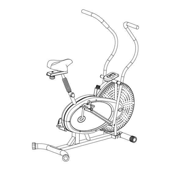
- Page 1 BRF 650 BRF 750 Upright Fan Bike * This item is for consumer use only and it is not meant for commercial use. OW NE R’S MA NUAL...
- Page 2 5. ALWAYS use your Equipment in a warm, dry, level well-lit and ventilated 11. NEVER use the Equipment if it does indoor area. not function properly. 6. ALWAYS keep body and clothing free and clear of all moving parts. BRF 650/750 Page 1...
-
Page 3: General Information
Telephone: (888) 266 - 6789 - 2 x Adjustable Wrenches Fax: (909) 598 - 6707 - 1 x Philips (”Crosshead”) Screw Driver Email: info@bodyflexsports.com Weight Limit Your product is suitable for users weighing: 250 pounds or less. BRF 650/750 Page 2... -
Page 4: Hardware List
[4 Pieces] [2 Pieces] pre-assembled OTHERS #27. Knob Bolt (M12x17 mm) #54. Knob Bolt (M8x36 mm) #52. Bushing [1 Piece] [1 Piece] [2 Pieces] pre-assembled pre-assembled #70. Tool 1 #71. Tool 2 [2 Pieces] [1 Piece] BRF 650/750 Page 3... -
Page 5: Parts Listing
Crankshaft Nut 2 Washer (M8) Washer for Crankshaft Horizontal Seat Bar Rectangular End Cap (25x50 mm) Friction Belt Seat Tool 1 Front Stabilizer Tool 2 End Cap for Front Stabilizer BRF 650/750 Page 4 BRM 3670 Stride Cycle Page ? -
Page 6: Exploded Diagram
3 0 6 0 2 5 1 5 7 4 8 4 1 5 2 5 7 4 6 4 BRF 650/750 Page 5... - Page 7 Secure the Rear Stabilizer (#42) to the Main Frame (#14) with two Carriage Bolts (#39), two Arc Washers (#40) and two Cap Nuts (#41). #41. Cap Nut (M10) [4 Pieces] WASHERS #40. Arc Washer (M10) [4 Pieces] LEFT REAR FRONT RIGHT BRF 650/750 Page 6...
-
Page 8: Pedal Assembly
Right Hand Side: Turn CLOCKWISE to tighten the Right Pedal (#53R) on the right crank. Then turn COUNTERCLOCKWISE to tighten the Right Nylon Nut (#49R) [WHITE inner nylon ring] to secure the right pedal assembly. #52. Bushing [2 Pieces] LEFT 52 51 51 52 RIGHT BRF 650/750 Page 7... - Page 9 Big Washer (#51) and the two pieces fit flushed together. Please refer to the exploded diagram for correct flushed together. Please refer to the exploded diagram for correct orientation and positioning. orientation and positioning. BRF 650/750 Page 8...
-
Page 10: Handle Bar Assembly
[***When assembling D Shape Washer (#22), please ensure side with the Left Handlebar (#19L) the flat edge matches and is flush with the corresponding flat edge of Handlebar Axle (#16) as marked in close-up diagram below.] LEFT RIGHT BRF 650/750 Page 9... - Page 11 Right Linkage (#44R) > Washer (#47) > Right of Left Linkage (#44L) > Washer (#47) > Left Handlebar (#19R) > Bolt (#45) Handlebar (#19L) > Bolt (#45) *RIGHT Side: **LEFT Side: INNER (SIDE) OUTTER (SIDE) OUTTER (SIDE) INNER (SIDE) 47 46 BRF 650/750 Page 10...
-
Page 12: Seat Assembly
(#30). Please refer to the illustration below. Always ensure that the Knob Bolt (#27) is securely tightened and engaged through the hole on the Main Frame (#14) and the hole setting most comfortable to you on the Seat Tube (#30) for your safety. BRF 650/750 Page 11... - Page 13 The assembly process is now complete. However, for your own safety, please make sure to read this entire Owner’s Manual which includes safety instructions and warnings, as well as any safety/warning labels affixed to the product before use. For your safety, please visually and functionally inspect and test the unit after assembly is complete. BRF 650/750 Page 12...
- Page 14 “test” when you gently tug on Friction Belt (#69) away from flywheel) 1-inch NOTE: In order to clearly show parts used in Tension Adjustment process, this drawing has been modified and does not show all parts nor full assembly. BRF 650/750 Page 13...
-
Page 15: Safety And Maintenance
(909) 598-9876, or mail in a written request to: Body Flex Sports, Inc. 21717 Ferrero Parkway, Walnut, CA 91789. More detailed information about how to reach our CUSTOMER SUPPORT may be found on Page 1 of the Owner’s Manual under the “CUSTOMER SUPPORT” section. Page 14 BRF 650/750... -
Page 16: Specifications
The computer is intended only as an exercise aid to track relative progress when using the corresponding exercise unit. BRF 650/750 Page 15... - Page 17 Proof of purchase Model Number BRF650/750 version: 07-02-2016 BRF 650/750...
- Page 18 This page intentionally left blank...
- Page 19 This page intentionally left blank...
- Page 20 Body Flex Sports, Inc. • 21717 Ferrero Parkway, Walnut, CA 91789 • Telephone: (888) 266 - 6789 • Email: info@bodyflexsports.com MADE IN CHINA...
Need help?
Do you have a question about the BRF 650 and is the answer not in the manual?
Questions and answers