Table of Contents
Advertisement
Quick Links
This service manual provides a variety of service
information. It contains the mechanical structure of
the CD-ROM Drive together with mechanical
adjustments and the electronic circuits in schematic
• Enhanced IDE interface
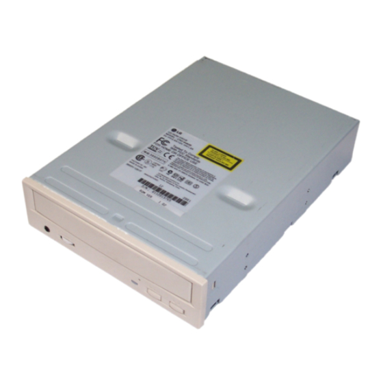
• Internal 5.25 inch, halfheight CD-ROM Drive
• Fast 75ms Average Access Time
• Max 6,000KB/sec Sustained Transfer rate
• Photo-CD Multisession Disc Spec compliant
• Multimedia MPC-3 Spec compliant
• Power Tray Loading/Ejection Mechanism
• 3 Way Eject support (Software, O/C Button,
Emergency Eject)
• Closed Enclosure
• Built-in ATAPI Interface Controller
1. SUPPORTED SYSTEM
• IBM Compatible 486SX or Above (With PIO mode 4 recommended)
2. SUPPORTED OS
• MS-DOS Version 3.1 or Higher
• OS/2 Warp (Ver 3.0)
• Windows '95/'98
3. GENERAL PERFORMANCE
• Data Transfer Rate..........................................................................................Sustained Data Transfer Rate
• Data Buffer Capacity .....................................................................................................................128 kbytes
• Access Time ...................................................................................................Random Access Time : 75 ms
4. POWER REQUIREMENTS
• Voltage.......................................................................................................................................+5V DC + 5%
• Ripple...................................................................................................................+5V : Less than 100mVp-p
• Current........................................................................................................................+5V : 0.9A (Maximum)
5. AUDIO PERFORMANCE
• Frequency Response .....................................................................................................20Hz~20KHz( + 3dB)
• S/N Ratio (IHF-A+20 KHz LPF)........................................................................85 dB (Typical at 1 KHz 0dB)
• T.H.D. (IHF-A+20 KHz LPF) ............................................................................0.05% (Typical at 1 KHz 0dB)
• Channel Separation (IHF-A+20 KHz LPF)..............................................................................80 dB (Typical)
• Output Voltage (1kHz 0dB) 47KΩ Load .................................................................................0.7Vrms + 10%
• Headphone Level (1kHz 0dB) 33Ω Load ...............................................................................0.7Vrms + 20%
INTRODUCTION
GENERAL FEATURE
SPECIFICATIONS
form. This CD-ROM Drive was manufactured and
assembled under our strict quality control standards
and meets or exceeds industry specifications and
standards.
• Software Volume Control
• 8 Times Digital Filter for CD Audio
• Front panel Volume Control for Headphone Output
• Built-in MODE-1 ECC/EDC
• MTBF 125,000h POH (at 10% Utilization)
• PIO Mode 4 & Multi DMA Mode 2 support
• Horizontal or Vertical Mounting
• Digital audio output connector
• Digital audio through ATAPI Interface
• Subcode (P-W) through ATAPI Interface
• Spin-down Mode for energy saving
• Solaris Ver 2.4 or Higher
• Linux slackware Ver 2.3
• Windows NT 4.0 or later
18Times Speed (Inner side) : 2,700 kbytes/sec
40 Times Speed (max., Outer side) : 6,000 kbytes/sec
+12V DC + 5%
+12V : Less than 100mVp-p
+12V : 1.5A (Maximum)
80 dB (Limit at 1 KHz 0dB)
0.15% (Limit at 1 KHz 0dB)
70 dB (Limit)
3
Advertisement
Table of Contents

Related Manuals for LG CRD-8402B


Summary of Contents for LG CRD-8402B
-
Page 1: Specifications
INTRODUCTION This service manual provides a variety of service form. This CD-ROM Drive was manufactured and information. It contains the mechanical structure of assembled under our strict quality control standards the CD-ROM Drive together with mechanical and meets or exceeds industry specifications and adjustments and the electronic circuits in schematic standards. -
Page 2: General Feature
INTRODUCTION This service manual provides a variety of service form. This CD-ROM Drive was manufactured and information. It contains the mechanical structure of assembled under our strict quality control standards the CD-ROM Drive together with mechanical and meets or exceeds industry specifications and adjustments and the electronic circuits in schematic standards. -
Page 3: Location Of Customer Controls
LOCATION OF CUSTOMER CONTROLS FRONT COMPACT Figure 1. Front View Headphone Jack Play/Skip Button 3.5mm jack for monitoring the audio signal from audio When an Audio CD is in the Disc Drawer, pressing CDs. this button will start playing audio CDs from the first track. -
Page 4: Troubleshooting Guide
TROUBLESHOOTING GUIDE 1. Initial Lead-in Operation Reset or Power-On. LED Flickers. Pick-Up moves to the inner-Track. Laser on the Pick-Up lights. Focus Search (through moving up and down the lens of Pick-Up) Focus Servo On (FOK Port : H, FEO(TP15) signal generation) Rotate disc. - Page 5 3. Troubleshooting Guide A. LED doesn’t light. Check Power Voltage Check the power input (TP1:3.3V, TP2:12V, TP20:2.7V) pattern. Reference Voltage [TP3:DVC(1.4V) and GND.] Is the CLOCK Frequency of Does “H” output in IC401 IC401 pin 16.93MHz? Check and replace R705, Check IC401.
- Page 6 B. Pick-Up doesn’t move to the inner track. Do the signals appear at IC401 pin Check IC401. (Refer to Fig. B-1.) Check the pattern from Does “H” output at IC201 IC401 pin to IC201 Check the R290, R291 Is the 1.4V at IC201 pin and C290 and then replace IC103.
- Page 7 C. The Laser of Pick-Up doesn’t light. Does “Low” or “High” Check R118 and replace output at IC102 pin IC401. Is the voltage of IC102 pin Check Q101, C101, C102 (LD) 2V? and then replace IC102. Check Pick-Up FFC, PN101. D.
- Page 8 Check the pattern from of IC201 to of PN101. Replace PN101 or Pick-Up Check the PN101, Pick-Up FFC. FFC. Replace the Pick-Up. TP10(F+) TP11(F-) (FAO) Fig. D-1. FAO Signal Fig. D-2. Focus Search Signal...
- Page 9 E. Disc doesn’t rotate. Does the signal appear at Does the signal appear at FOK (TP18) during focus FEO (TP15) when the Replace Pick-Up. search? R505 opened? (Refer to Fig. E-1.) (Refer to Fig. E-2.) Replace IC501. Do the signal appear at TP15 (FEO) and TP19 Replace IC501.
- Page 10 TP10: TP15: S-Curve TP18: Fig. E-1. FOK, F+ Signal Fig. E-2. S-Curve (R505:Open) TP15: TP25: TP19: SENS Fig. E-3. FEO, SENS Signal Fig. E-4. MDP Signal...
- Page 11 F. TOC isn’t read. Is the Focus Servo ON? Does A, B, C, D signal (Does FEO (TP15) signal appear at IC102 pin appear?) Replace IC102. Refer to C. (The Laser of Pick-Up Is the Tracking Servo ON? Does E, F signal appear doesn’t light.) (Does TEO (TP14) signal at IC102 pin...
- Page 12 G. During Audio CD play, LED flickers, but Speaker is silent. Does PWM signal appear at Replace IC501. IC501 pin 134 135 142 143 (Refer to Fig. G-1.) Does Audio signal appear Is the voltage of IC601 Check the R601, R602 at IC601 pin 2.5V? and C602.
- Page 13 Is the connection between JK801 (or Audio Check the JK801 and Line out connector) and Audio line pattern. Line (or Jack) normal? Check your sound card, Audio Cable, Speaker, Volume and Headphone Jack. PIN6 of PIN3 of IC601 IC601 PIN10 of IC601 PIN12 of IC601...
-
Page 14: Cabinet And Circuit Board Disassembly
DISASSEMBLY 1. CABINET and CIRCUIT BOARD 1-3. Cabinet and Main Circuit Board A. Remove the Cabinet in the direction of arrow (4). DISASSEMBLY (See Fig. 1-3) 1-1. Bottom Chassis B. Release 2 hooks (a) and remove the CD Tray. A. Release 4 screws (A) and remove the Bottom C. - Page 15 PHOTO DIODE STRUCTURE OF THE PICK-UP (1) Focus Error Signal –> (A+C)-(B+D) (Control the Pick-up’s up and down to focus on the Disc) (2) Tracking Error Signal –> (E-F) (Control the Pick-up’s left and right shift to find the track on the Disc) (3) RF Signal –>...
-
Page 16: Block Diagram
IC INTERNAL BLOCK DIAGRAM AND PIN DESCRIPTION • IC102 (CXA2581N) : RF Amplifier IC I-V converts and amplifies the signal received from the pick-up and then applies to DSP part of one- chip IC (IC501). Block Diagram AC_SUM EQ_IN Pin Description Pin No. - Page 17 • IC201 (M63020FP) : Drive IC (Spindle/Servo Actuator) Rotates the Spindle Motor by receiving MDP signal from IC501. Generates the signal to drive Focus Actuator Coil, Tracking Actuator Coil, Sled Motor, and Stepping Motor by Control Signal input from DSP and u-COM. Block Diagram Reverse Detect...
- Page 18 • IC401 (M37903F8CHP) : Shrink µ-com [MODEL : CRD-8402B(s)] Controls all Drive systems by input and output the Data from the peripheral IC. • IC501 (CXD3030R) : DSP+ATAPI DECODER+DRAM Block Diagram XINT XWAT PWM2N PWM2P PWM1N PWM1P DOUT SENS MIRR...
- Page 19 • IC501 CXD3030R Pin Description Pin No. Symbol Description AVS6 Analog GND Analog DAC Analog Output of Slide Filter Analog DAC Analog Output of Tracking Filter Analog DAC Analog Output of Focus Filter BSSD Constant Current Input for DAC Analog of Servo Filter AVD6 Analog Power Supply (2.5V) VSIO0...
- Page 20 Pin No. Symbol Description Focus Error Input Center voltage Input VPCO1 1,Z,0 Output of VCO2 for wide-Band EFM PLL VCTL Input of VCO2 Control voltage for Wide-Band EFM PLL FILO Analog Filter Output for Master PLL (Slave = Digital PLL) FILI Filter Input for Master PLL 1,Z,0...
- Page 21 Pin No. Symbol Description Data Write Strobe Signal from Sub CPU, Negative Logic Data Read Strobe Signal from Sub CPU, Negative Logic Sub CPU Address (MSB) Sub CPU Address Sub CPU Address Sub CPU Address Sub CPU Address Sub CPU Address Sub CPU Address (LSB) 1,Z,0 Sub CPU Data Bus...
- Page 22 Pin No. Symbol Description VSIO5 Digital Power Supply GND HDBD 1,Z,0 Host Data Bus HDB2 1,Z,0 Host Data Bus HDBC 1,Z,0 Host Data Bus HDB3 1,Z,0 Host Data Bus VDIO3 Digital Power Supply (3.3V) HDBB 1,Z,0 Host Data Bus HDB4 1,Z,0 Host Data Bus HDBA...
- Page 23 • GTOP monitors the state of Frame Sync protection. ("H" : Sync protection window released) • XPLCK is an inversion of the EFM PLL clock. The PLL is designed so that the falling edge of XPLCK coincides with a change point of the EFM signal. •...
- Page 24 BLOCK DIAGRAM CLOCK 33.86MHz CXA2581N CXD3030R RF Amp. DSP + I/F Cable Optical DRAM + Disc Pick-up Motor unit 16.93MHz SPINDLE FOCUS TRACKING SLED LOADING MOTOR COIL COIL MOTOR MOTOR M37903F8CHP R-ch System AUDIO Controller L-ch Circuitry M63020FP MOTOR DRIVE Line-out Headphone Jack...
- Page 25 EXPLODED VIEW PBM00 (MAIN C.B.A)
Need help?
Do you have a question about the CRD-8402B and is the answer not in the manual?
Questions and answers