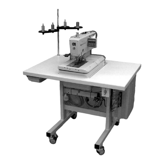
DURKOPP ADLER 559 Operating, Installation And Servicing Instructions
Automatic single-chainstitch eyelet machine
Hide thumbs
Also See for 559:
- Parts list (107 pages) ,
- Operating instructions manual (36 pages) ,
- Instruction manual (258 pages)
Table of Contents
Advertisement
Quick Links
Automatic double-chainstitch buttonholer
Automatic single-chainstitch eyelet machine
Postfach 17 03 51, D-33703 Bielefeld Ÿ Potsdamer Straße 190, D-33719 Bielefeld
Telefon +49 (0) 5 21/ 9 25-00 Ÿ Telefax +49 (0) 5 21/ 9 25 24 35 Ÿ www.duerkopp-adler.com
Ausgabe / Edition:
10/2005
Operating Instructions
Installation Instructions
Printed in Federal Republic of Germany
559
Service Instructions
Teile-Nr.:/Part-No.: 0791 559001
1
2
3
Advertisement
Table of Contents

Related Manuals for DURKOPP ADLER 559


Summary of Contents for DURKOPP ADLER 559
-
Page 1: Operating Instructions
Automatic double-chainstitch buttonholer Automatic single-chainstitch eyelet machine Operating Instructions Installation Instructions Service Instructions Postfach 17 03 51, D-33703 Bielefeld Ÿ Potsdamer Straße 190, D-33719 Bielefeld Telefon +49 (0) 5 21/ 9 25-00 Ÿ Telefax +49 (0) 5 21/ 9 25 24 35 Ÿ www.duerkopp-adler.com Ausgabe / Edition: 10/2005 Printed in Federal Republic of Germany... - Page 2 Anleitung, komplett / Manual, complete Übersicht Summary Bedienanleitung Operating Instructions Aufstellanleitung Installation Instructions Serviceanleitung Service Instructions Bauschaltplan Interconnection-diagram 9890 580001 B 9890 580001 B...
-
Page 3: Table Of Contents
Index Page: Part 3: Service Instructions Class 559 General notes Necessary program setting ......... - Page 4 Index Page: Hook height..........Adjusting the looping stroke .
-
Page 5: General Notes
General notes The service manual on hand describes the adjustment of the automatic buttonholer 559 in an appropriate sequence. ATTENTION ! Various setting positions are interdependent. Therefore it is absolutely necessary to make the individual adjustments following the described order. -
Page 6: Adjusting The Locking Positions
The positions have been set by the manufacturer in such a way that standard material can be sewn with the 559. If you want to use other needle sizes, thread sizes or materials, you may have to set positions slightly differing from the staking-out position. -
Page 7: Hook And Spreader Eccentric
Hook and spreader eccentric Caution: Danger of injury! Switch the main switch off. Adjust the eccentrics only with the sewing machine switched off. Standard checking When the arm shaft is staked out with arresting pin 1, it should be possible to stake out the hook eccentric 3 and the spreader eccentric 4, too. -
Page 8: Rotary Thread Take-Up Disc
Rotary Thread Take-up Disc Caution: Danger of injury! Switch the main switch off. Adjust the rotary thread take-up disc only with the sewing machine switched off. Standard checking When the arm shaft has been arrested through the aressting pin 2, so that the hook holder is in the left end position (left entry point), the rotary thread take-up disc 6 should be in the right position for a needle 4 that is put on the bore hole of the rotary thread take-up... -
Page 9: Throw Eccentric
Throw eccentric Caution: Danger of injury ! Switch the main switch off. Adjust the rotary thread take-up disc only with the machine switched off. Standard checking When the hook support 5 is in ist right end position (right entry point), the arresting pin 4 inserted in the eccentric 2 shoould abut in the notching 1 at the arm. -
Page 10: Needle Bar Positioning
Needle bar positioning Caution: Danger of injury! Exercise utmost caution when making adjustments with the machine running. Standard checking When the machine positions automatically after being switched on, the needle bar must be in the top dead centre. The hook support is in its right end position (right entry point) then. -
Page 11: Aligning The Hook Support
Aligning the hook support Caution: Danger of injury! Switch the main switch off. Align the hook support only with the machine switched off. Note Please observe the necessary program setting as described in chapter 1.1. Standard checking When the machine has reached its initial position after switching on the main switch, it must be possible to stake out the hook support 2 with the arresting pin 1. -
Page 13: Aligning The Needle Bar Parallel To The Hook Support
Aligning the needle bar parallel to the hook support Caution: Danger of injury! Switch the main switch off. Adjust the needle bar only with the main switch switched off. Standard checking The needle bar 1 and the hook support 3 must be in parallel position. –... -
Page 15: Transversal Motion Of The Fabric Support Plate
Transversal motion of the fabric support plate Caution: Danger of injury! Exercise utmost caution when making adjustments with the machine running. Note Please observe the necessary program setting as described in chapter 1.1. Standard checking The hook support 3 must be in the centre of the fabric support plate 4. When the automatic buttonholer is in reference position, the dimensions X1 and X2 must be equal when the fabric support plate is adjusted correctly. - Page 16 Correction – Switch the machine on and press the keys “P” and “ß” on the control panel simultaneously. – Enter code “2548”. – Press key ”OK”. The control switches to the technician level. – Select the menu “603” with the key “+”. In this mode the step motors are dead.
-
Page 17: Longitudinal Motion Of The Fabric Support Plate
Longitudinal motion of the fabric support plate Caution: Danger of injury! Exercise utmost caution when making adjustments with the machine running. Note Please observe the necessary program setting as described in chapter 1.1. Standard checking When the machine is in reference position, the distance between the edge 3 of the fabric support plate 2 and the front edge 1 of the throat plate support should amount to approx. - Page 18 Correction – Switch the machine on and press the keys “P” and “ß” on the control panel simultaneously. – Enter code “2548”. – Press key ”OK”. The control switches to the technician level. – Select the menu “603”with the key “+”. In this mode the step motors are dead.
-
Page 19: Clamping Plates
Clamping plates Inserted clamping plates ô Caution: Danger of injury! Switch the main switch off. Adjust the clamping plates only with the machine switched off. Standard checking The inserted clamping plates 1 and 2 should be in the holding groove 4 of the fabric support plate in parallel position and without clearance. -
Page 20: Aligning The Clamping Plates As To The Fabric Support Plate
Aligning the clamping plates Caution: Danger of injury! Switch the main switch off. Adjust the clamping plates only with the machine switched off. Standard checking Both clamping plates 3 must be adjusted in such a way that the distance between clamping plate and fabric support plate 1 is equal everywhere (distance X1 = distance X2). -
Page 21: Adjusting The Spreading
Adjusting the spreading Caution: Danger of injury! Exercise utmost caution when making adjustments with the machine running. Standard checking The distance X between the clamping plates 2 and the fabric support plate 1 should amount to 1.3 mm (non-spreaded) and to 0.3 mm (spreaded). - Page 22 Correction clamping plate – Switch the machine on. – Press the keys “P” and “F” on the control panel simultaneously. – Enter code “2548”. – Press key ”OK”. The control switches to the technician level. – Select the menu “601” with the key “+”. –...
-
Page 23: Height Of The Fabric Clamps
8.4 Height of the fabric clamps Ø 12 mm Caution: Danger of injury! Switch the main switch off. Adjust the fabric clamp height only with the machine switched off. Standard checking The distance between the open fabric clamps 2 and 3 should amount to 12 mm. -
Page 24: Adjusting The Locking Sheet
Adjusting the locking sheet Caution: Danger of injury! Switch the main switch off. Adjust the locking sheets only with the machine switched off. Standard checking The locking sheets 1 must be adjusted in such a way that the stops 3 of the clamping plates abut centrally and as tight as possible. -
Page 25: Arrest Of The Clamping Plates
Arrest of the clamping plates Caution: Danger of injury! Exercise utmost caution when making adjustments with the machine running. Standard checking There must be a minimum clearance in the height of the inserted clamping plates 2 when: · no material is loaded ·... -
Page 26: Adjusting The Fabric Clamping Pressure
Adjusting the fabric clamping pressure Caution: Danger of injury! Switch the main switch off. Adjust the fabric clamping pressure only with the machine switched off. Standard checking The clamping pressure should be adjusted in such a way that the sewing material is clamped safely and tightly. Please observe that the sewing material is not damaged by a too high pressure. -
Page 27: Adjusting The Seam Width
Adjusting the seam width Presetting the seam width Caution: Danger of injury! Switch the main switch off. Adjust the seam width only with the machine switched off. Standard You can choose among two seam widths: · Seam width “Narrow” = Lever 2 mounted in position B ·... - Page 28 Press the “OK” key. – Set the sewing equipment (the seam width will then be adjusted automatically to match the sewing equipment - see table). Class Sewing equipment narrow wide 559 - 151 E1501 E1521 E1502 E1522 E1504 E1524 E1551...
- Page 29 Notes:...
-
Page 30: Needle Zero Position
Needle zero position Caution: Danger of injury! Switch the main switch off. Set the needle zero position only with the machine switched off. Standard checking The needle bar oscillates unidirectionally from the left (inside) to the right (outside). The needle zero position is on the left (inside). With the needle zero position the inner stitches of the forward and backward lip must be in a line. -
Page 31: Cutting Knife (Eyelet Knife)
10. Cutting knife (Eyelet knife) 10.1 Position of the cutting knife Caution: Danger of injury ! Switch the main switch off. Adjust the cutting knife only with the machine switched off. Standard checking In case of automates for “cutting after sewing” the cutting knife 2 should cut exactly between the seam rows and in the center of the eyelet (see illustration a). - Page 32 The cutting knife has to be adjusted in such a way that it cuts in the center of the sewn buttonhole shape. – Insert the cutting block. – Insert a short needle. – Load a piece of paper or cardboard as sewing material. –...
-
Page 33: Adjusting The Knife Parallel To The Cutting Block
10.2 Adjusting the knife parallel to the cutting block – Loosen screws 1, 2 and 3. – Put the key 4 (in the accessories) on the hexagonal bolt 5 and twist it. – Push the cutting block 6 downward. -
Page 34: Cutting Block Adjustment
10.3 Cutting block adjustment Caution: Danger of injury ! Switch the main switch off. Adjust the cutting block only with the machine switched off. The cutting length can be altered by changing the cutting block. The cutting length is determined by the cutting block length. Standard checking The cutting block 3 must be in parallel position to the cutting knife 4. -
Page 35: Cutting Pressure
10.4 Cutting pressure Standard checking The cutting pressure is adjustable in order to keep the strain of all components as low as possible and to increase the durability of the cutting knife. According to the sewing material and the material thickness the cutting pressure should be adjusted as low as possible. -
Page 36: Hook Height
11. Hook height Before adjusting the looping stroke as well as the needle bar height and particularly after needle breakage it is necessary to check the correct hook height. Use gauge 2 for checking the hook height. Caution: Danger of injury ! Switch the main switch off. -
Page 37: Adjusting The Looping Stroke
12. Adjusting the looping stroke Caution: Danger of injury ! Switch the main switch off. Adjust the looping stroke only with the machine switched off. Standard checking The looping stroke is the way of the needle bar from its lowest position up to the point where the left or right hook tip is at the level of the middle of the needle. - Page 38 Correction Shift the clamping rings 3 and 4 in such a way that both hook tips have the same distance to the needle. Adjust the left hook 8 and the right hook 7 so that both hook tips in looping stroke position have the same position (X) to the needle. That means both hook tips must be at an equal distance either before or behind the needle.
-
Page 39: Needle Bar Height
13. Needle bar height Caution: Danger of injury ! Switch the main switch off. Adjust the needle bars only with the machine switched off. Standard checking The needle bar has to be adjusted in such a way that approx. 3/4 of the needle’s eye 6 is to be seen under the left hook tip when the needle bar has moved upward by 2.5 mm from the looping stroke position. -
Page 40: Distance Between Hook And Needle
14. Distance between hook and needle Caution: Danger of injury ! Switch the main switch off. Adjust the needle protection only with the machine switched off. Standard checking The hook tips 1 and 4 should be in a distance of max. 0.1 mm to the needle 3. -
Page 41: Needle Guard
15. Needle guard Caution: Danger of injury ! Switch the main switch off. Adjust the needle guard only with the machine switched off. Standard checking The needle 1 must slightly abut on the needle guard 2 until the hook tips have reached the needle. The distance between hook and needle must amount to 0.1 mm. -
Page 42: Spreader
16. Spreader Caution: Danger of injury ! Switch the main switch off. Adjust the spreader only with the machine switched off. Standard checking The distance between the fork spreader 5 and the left hook 4 must correspond to the thickness of the hook thread used (see illustration X opposite). -
Page 43: Spreader Plate
17. Spreader plate Caution: Danger of injury ! Switch the main switch off. Adjust the spreader plate only with the machine switched off. Standard checking The opening and closing of the spreaders is effected by the alternate motion of the spreader plate 2. When the needle bar is in the bottom dead centre for the right stitch, the distance between spreader plate 2 and spreader shank 1 must be exactly the same as that between spreader plate 2 and spreader shank... -
Page 44: Throat Plate
18. Throat plate Caution: Danger of injury ! Switch the main switch off. Adjust the throat plate only with the machine switched off. Standard checking The needle should penetrate the needle hole of the throat plate on one side at the edge 1. The throat plate has to be positioned as highly as possible. -
Page 45: Adjusting The Needle Thread Knife
19. Adjusting the needle thread knife Caution: Danger of injury ! Switch the main switch off. Adjust the needle thread knife only with the machine switched off. Standard checking The cutting motion of the needle thread knife 2 is effected after sewing. The exact cutting moment is fixed in the control. - Page 46 Correction of the knife motion – Loosen the counter-nuts 5 and 8. – Adjust the stop screws 6 and 7 according to the rule. – Tighten the counter-nuts 5 and 8. Adjusting the height of the knife – Loosen screw 10. –...
-
Page 47: Adjusting The Fabric Clamps
20. Adjusting the fabric clamps Caution: Danger of injury ! Switch the main switch off. Adjust the fabric clamps only with the machine switched off. Standard checking Between the needle 2 and the upper fabric clamp 1 there should be a distance of 1 mm over the whole length and in the eyelet. -
Page 48: Thread Controller Spring
21. Thread controller spring Caution: Danger of injury ! Switch the main switch off. Adjust the thread controller spring only with the machine switched off. Standard checking The thread controller spring 1 must hold the hook thread tensioned until the needle with the needle thread has accurately penetrated the triangle formed by the spreader. -
Page 49: Maintenance
22. Maintenance Caution: Danger of injury ! Switch the main switch off. Maintenance work of the automatic buttonholer must only be carried out with the machine switched off. The daily or weekly maintenance work (cleaning and oiling) to be carried out by the operators of the automatic buttonholer is described in Part 1: Operating Instructions. -
Page 50: Annex
23. Annex 23.1 Adjusting operations without head cover When the head cover is taken off, the machine is secured against unintentional starting. If you want to operate the machine without head cover for adjusting purposes, the plug 2 can be put on the connecting cable 3. The plug is in the switch casing 1. -
Page 51: Fuses In The Control Box
23.2 Fuses in the control box The fuses 1 and 2 for the control are on the back of the control box. Only insert the fuses indicated in the circuit diagram. 23.3 Exchange of the control See: Part 2: Installation Instructions. ·... -
Page 52: Service Menu (Technician Level)
24. Service menu (technician level) In the service menu of the 559 various basic adjustments and test programs can be executed. 24.1 Activating the service menu – Press the keys “P” and “F” simultaneously on the control panel. A code query appears. -
Page 53: List Of Menu And Submenu Items
24.5 List of menu and submenu items Menu item Description Configuration automatic buttonholer Loading position Throw width Thread monitor Duty cycle of the cutting block Sewing equipment Configuration operation Push button Brightness of sewing lamp Brightness of the display Keyboard signal Multitest Output test Manual input test... -
Page 54: Menu Items 500 (Configuration Automatic Buttonholer)
24.6 Menu items 500 (Configuration automatic buttonholer) 24.6.1 Menu item 501 (Loading position) Via this menu item the desired loading position can be set. Input: 0 … 68 (mm) Standard: 68 The value entered corresponds to the distance from the cutting point. The value “0”... -
Page 55: Menu Items 550 (Configuration Operation)
24.6.5 Menu item 511 (Sewing equipment) Various sewing equipment can be used with the automatic buttonholer 559. The selected sewing equipment is entered via this menu item. Input: 1501, 1502, 1504, 1521, 1522, 1524, 1551, 1553 or 1573, 1590, 1595. -
Page 56: Menu Items 600 (Multitest)
24.7.4 Menu item 554 (Keyboard signal) In this menu the keyboard signal is switched on and off. The set value means: = Keyboard signal off 1 .. 50 = Keyboard signal in milli-seconds Standard: 0 – Quit the menu item with key “ESC”. 24.8 Menu item 600 (Multitest) 24.8.1 Menu item 601 (output test) - Page 57 24.8.2 Menu item 602 (manual input test) Caution: Danger of injury! Exercise utmost caution when making the input test with the machine running. In this menu individual input elements can be tested. – Select the desired input element with the keys “ñ” or “ò”. The current status is indicated in the display: = input inactive = input active...
- Page 58 24.8.4 Menu item 604 (sewing motor test) With this menu item the sewing motor can be checked. During the test the speed can be increased in steps of 100. Caution: Danger of breakage ! Before starting the sewing motor test remove the clamping plates in any case.
- Page 59 24.8.6 Menu item 606 (ROM or flash test) In this menu item the read-only memory (ROM) and the flash memory are checked. Display: on the left: Calculated checksum on the right: 1 = Memory OK 0 = Memory not OK –...
- Page 60 Caution Risk of injury ! The testing program serves only for the checking of cycles and functions. Maintenance and setting work should not be conducted when running the testing program. The following is the meaning values set: 0= normal sewing cycle, the testing program is turned off. 1= the sewing cycle is stopped after switching the valves of the thread catcher on.
-
Page 61: Error Messages
25. Error messages Error Info/Description Remedy Sewing motor timeout · Replace the cable 1051 · Cable to the sewing motor reference switch faulty · Reference switch defective · Replace the reference switch 1052 Sewing motor excess current · Cable of sewing motor faulty ·... - Page 62 Error Info/Description Remedy 2155 · Step motor X-axis · Eliminate the blocking/rough overcharge running · Step motor X-axis · Replace step motor X-axis blocked/moves too heavy · Replace the control · Step motor X-axis defective · Control defective 2156 · Step motor X-axis ·...
- Page 63 Error Info/Description Remedy 2301 · Step motor Z-axis · Replace the cable timeout reference · Replace the reference switch · Cable to the reference switch faulty ·Reference switch defective 2302 · Step motor Z-axis · Eliminate the blocking Current supply fault ·...
- Page 64 Error Info/Description Remedy 3300 · Fault in the machine control · Switch the machine off and on · Internal fault again 3724 · Software update · Inform DA-Service 4460 · Operation BF-4 · Switch the machine off and on · Malfunction again 4468 ·...
- Page 65 Error Info/Description Remedy 8251 · ADSP Boot / · Switch the machine off and on 8255 Boot failure again · Internal fault · Software update · Inform DA-Service 8252 · Boot failure · Switch the machine off and on · Malfunction again 8254 8256...
-
Page 66: Troubleshooting
26. Troubleshooting Caution: Danger of injury! Exercise utmost caution when eliminating defects with the machine switched on. Description of fault Possible cause Error elimination The display shows a message indicating the possible cause. The automate does not start up. Display: Info 200 Turn the handwheel in the direction Before sewing start the needle of rotation so that the needle is in... - Page 67 Description of fault Possible cause Error elimination Skipped stitches The material is not spread or Check the spreading spread too little. (see chapter “Spreading”). The matching needle size has Change the needle size. to be chosen according to the (See Operating Instructions) material, the material thickness Attention! and the thread used.
- Page 68 Description of fault Possible cause Error elimination Thread breakage Thread-guiding parts as e.g. Check whether thread-guiding parts thread pipes, thread guides or are sharp-edged. the rotary thread take-up disc have sharp edges. Check whether the throat plate, Have the parts reworked by the the hooks or the spreaders service personnel.
- Page 69 Description of fault Possible cause Error elimination Needle breakage The needle size is unsuitable Change the needle size. for the material or the thread. The needle hits the fabric Check the subclass on the control clamps panel. When changing the seam width Set the upper fabric clamps apart the upper fabric clamps have as far as required.
- Page 70 Description of fault Possible cause Error elimination Faulty rotation of the sewing Possible rough running of Check all components belonging to works individual components the sewing works rotation. If neither faulty components nor rough running are found, the problem can in some cases be solved by altering the following parameters: - Speed reduction...
Need help?
Do you have a question about the 559 and is the answer not in the manual?
Questions and answers