Advertisement
Table of Contents
Advertisement
Table of Contents

Related Manuals for Challenge Xtreme BMS210K.1


Summary of Contents for Challenge Xtreme BMS210K.1
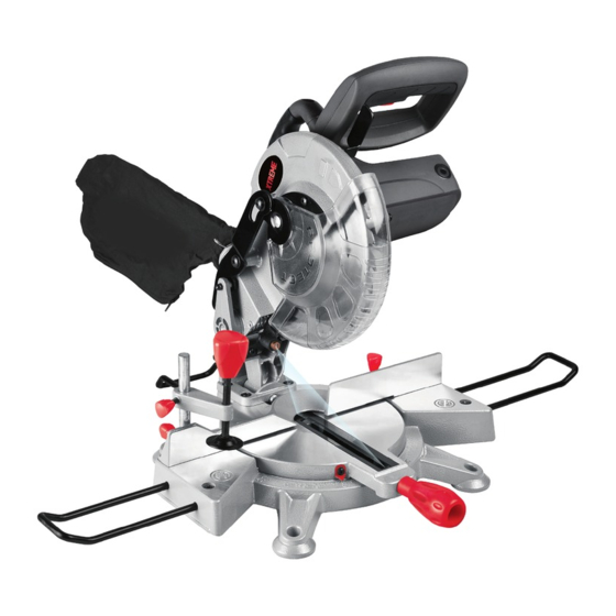
- Page 1 8” COMPOUND MITRE SAW WITH LASER BMS210K.1...
-
Page 2: Safety Instructions
SAFETY INSTRUCTIONS - Non-skid footwear is recommended when working outdoors. WARNING: When using electric - Wear protective hair covering to contain tools basic safety precautions should long hair. always be followed to reduce the risk of fire, 9 - Use protective equipment electric shock and personal injury including - Use safety glasses. - Page 3 - Ensure switch is in “off” position when – for tools provided with a PRCD: Never plugging in use the tool without the PRCD delivered 18 - Use outdoor extension leads with the tool, - When the tool is used outdoors, use –...
- Page 4 materials e.g. wood chips and timber off supply. cuts. 12. Never try to cut freehand. Always ensure 14. Use correctly sharpened saw blades, that the workpiece is securely pressed against the straight guide and blade support Observe the maximum speed marked on surface.
- Page 5 SYMBOLS 3. The laser beam shall not be deliberately aimed at another person and shall be prevented from being directed towards the eye of a person for longer than 0.25 Read the manual seconds area. 4. Always ensure the laser beam is aimed at a sturdy work piece without Warning reflective surfaces, e.g.
-
Page 6: Component List
COMPONENT LIST 1. Upper blade guard 17. Trigger switch 2. Dust bag 18. Transportation handle 3. Safety guard mounting plate 19. Handle 4. Saw blade 20. Lock pin (See E) 5. Fence 21. Locking screws for straight guide (See K) 6. - Page 7 TECHNICAL DATA Voltage 230-240V~50 Hz Power input S1. 1200W, S6. 25% 1500W No load speed 5000min Bevel capacity 0 - 45º Miter capacity 0-45º (L & R) Cutting capacity: Miter/Bevel: 0°/0° 120 x 60 mm Miter/Bevel: 0°/45° 120 x 35 mm Miter/Bevel: 45°/0°...
- Page 8 OPERATING INSTRUCTIONS or both sides of the base. Secure them in place by tightening clamp screw on the NOTE: Before using the tool, read the base. instruction book carefully. The table extension rail is used for supporting the long pieces. ASSEMBLY 1.
-
Page 9: Mounting Holes
4. MOUNTING HOLES (SEE C) OPERATION 1. TO MAKE A CUT 1. When boxed or during storage, transportation, the saw head is locked in the down position. To release the head ready for operation, apply downward pressure and pull out the lock pin (20). 2. -
Page 10: Laser Guide
3. BEVEL CUTS (SEE F1, F2)) angles is possible. Fig.G shows the saw with 45º set on the rotary table and the saw head tilted 45º. 5. LASER GUIDE (See H) Fig. F1 Fig. H The laser guide (21) equipped with this machine is for the purpose of precision cutting. -
Page 11: Precision Setting Of Angles
other fittings are securely tightened. adjustments). To confirm the 0º rotary table setting, set the There are no user serviceable parts in your rotary table at 0º and tighten the rotary table power tool. Never use water or chemical locking knob. Check that the angle between cleaners to clean your power tool. -
Page 12: Changing Saw Blade
2. CHANGING THE SAW BLADE (SEE M, Fig. O 3. REPLACING THE CARBON BRUSHES Fig. M (SEE P) Disconnect the saw from the power supply. Lower the saw head until the blade securing bolt can be seen. Press blade spindle lock (f) and rotate the blade until it is locked, then loosen and remove the blade securing bolt, and outer flange with the hex key in clockwise... -
Page 13: Plug Replacement
PLUG REPLACEMENT Your Power Tool is supplied with a fitted plug, however if you need to fit a new plug follow the instruction below. IMPORTANT The wires in the mains lead are coloured in accordance with the following code: Blue = Neutral Brown = Live As the colours of the wires in the mains lead of this appliance may not correspond with the coloured markings identifying the terminals in your plug, proceed as follows: The wire which is coloured blue must be... - Page 14 HELPLINE NO 08707252949...
- Page 15 HELPLINE NO 08707252949...
Need help?
Do you have a question about the BMS210K.1 and is the answer not in the manual?
Questions and answers
Czy można kupić wirnik do tej piły i jaka jest cena.