Table of Contents
Advertisement
Model Number:
5900605
5900606
5900607
Ferris Industries
5375 North Main Street
Munnsville, NY 13409
800-933-6175
OPERATOR'S
MANUAL
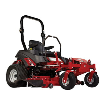
IS1500Z Series
Zero-Turn Riding Mower
Description
IS1500ZKAV1944, 19HP, 44" Cut Zero-Turn Riding Mower
IS1500ZKAV2148, 21HP, 48" Cut Zero-Turn Riding Mower
IS1500ZKAV2552, 25HP, 52" Cut Zero-Turn Riding Mower
5100792
Revision 01
Rev. Date: 9/2006
TP 100-7305-01-15-F
Advertisement
Table of Contents
Troubleshooting

Related Manuals for Ferris 5900605


Summary of Contents for Ferris 5900605
- Page 1 Model Number: 5900605 5900606 5900607 Ferris Industries 5375 North Main Street Munnsville, NY 13409 800-933-6175 OPERATOR’S MANUAL IS1500Z Series Zero-Turn Riding Mower Description IS1500ZKAV1944, 19HP, 44” Cut Zero-Turn Riding Mower IS1500ZKAV2148, 21HP, 48” Cut Zero-Turn Riding Mower IS1500ZKAV2552, 25HP, 52” Cut Zero-Turn Riding Mower...
- Page 2 Copyright © 2006 Briggs & Stratton Corporation Milwaukee, WI, USA. All rights reserved. The Ferris logo is a trademark of Briggs & Stratton Corporation Milwaukee, WI, USA. Contact Information: Ferris Industries. 5375 N. Main St. Munnsville, NY 13409-4003 (800) 933-6175 www.ferrisindustries.com...
-
Page 3: Table Of Contents
Table of Contents Safety Rules & Information ...2 Identification Numbers ...11 Safety Decals ...12 Safety Interlock System...13 Features & Controls ...14 Control Functions...14 Operation ...16 General ...16 Checks Before Starting ...16 Starting the Engine ...17 Stopping the Rider ...17 Pushing the Rider by Hand...17 Zero Turn Driving Practice ...18 Mowing...20 Mowing Reccomendations...20... -
Page 4: Safety Rules & Information
Safety Rules & Information Read the Manual The operator’s manual contains important safety information you need to be aware of BEFORE you operate your unit as well as DURING operation. Safe operating techniques, an explanation of the product’s features and controls, and maintenance information is included to help you get the most out of your equipment investment. -
Page 5: Slope Operation
Thrown Objects This unit has spinning mower blades. These blades can pick up and throw debris that could seriously injure a bystander. Be sure to clean up the area to be mowed and remove objects that could be thrown by the blade BEFORE you start mowing. - Page 6 Safety Rules & Information Retaining Walls, Drop- offs, and Water Retaining walls and drop-offs around steps and water are a common hazard. Give yourself a minimum of two mower widths of clearance around these hazards and hand-trim with a walk behind mower or string trimmer.
- Page 7 Enclosed Areas Only operate this unit outdoors and away from unventilated areas such as inside garages or enclosed trailers. The engine emits poisonous carbon monoxide gas and prolonged exposure in an enclosed area can result in serious injury or death. Safety Rules &...
-
Page 8: Operation
Safety Rules & Information Read these safety rules and follow them closely. Failure to obey these rules could result in loss of control of unit, severe personal injury or death to you, or bystanders, or damage to property or equipment. This mowing deck is capable of amputating hands and feet and throwing objects. The triangle in text signifies important cautions or warnings which must be followed. - Page 9 23. Use care when approaching blind corners, shrubs, trees or other objects that may obscure vision. 24. To reduce fire hazard, keep unit free of grass, leaves & excess oil. Do not stop or park over dry leaves, grass or combustible materials. 25.
-
Page 10: Service And Maintenance
Safety Rules & Information SERVICE AND MAINTENANCE To avoid personal injury or property damage, use extreme care in handling gasoline. Gasoline is extremely flammable and the vapors are explosive. Safe Handling of Gasoline 1. Extinguish all cigarettes, cigars, pipes, and other sources of ignition. - Page 11 27. Models equipped with an engine radiator: WARNING: Stored energy device. To prevent serious bodily injury from hot coolant or steam blow-out, never attempt to remove the radiator cap while the engine is running. Stop the engine and wait until it is cool. Even then, use extreme care when removing the cap.
- Page 12 Safety Rules & Information WARNING Failure to properly inspect and maintain the seat belt can cause serious injury or death. INSPECTION AND MAINTENANCE OF THE ROLL BAR SEAT BELT • The seat belt like the ROLL BAR, needs to be periodically inspected to verify that the integrity has not been compromised through normal machine use, misuse, age degradation,...
-
Page 13: Identification Numbers
Identification Numbers Identification Numbers Identification When contacting your authorized dealer for replacement parts, service, or information you MUST have these numbers. Record your part number, serial number and engine serial numbers in the space provided for easy access. These numbers can be found in the locations shown. NOTE: For location of engine identification numbers, refer to the engine owner’s manual. -
Page 14: Safety Decals
Safety Decals SAFETY DECALS This unit has been designed and manufactured to provide you with the safety and reliability you would expect from an industry leader in outdoor power equipment manufacturing. Although reading this manual and the safety instructions it contains will provide you with the necessary basic knowledge to operate this equipment safely and effectively, we have placed several safety labels on the unit to remind you of this important... -
Page 15: Safety Interlock System
SAFETY INTERLOCK SYSTEM This unit is equipped with safety interlock switches. These safety systems are present for your safety, do not attempt to bypass safety switches, and never tamper with safety devices. Check their operation regularly. Operational SAFETY Checks Test 1 — Engine should NOT crank if: •... -
Page 16: Features & Controls
Features & Controls Figure 1. Control Locations CONTROL FUNCTIONS The information below briefly describes the function of individual controls. Starting, stopping, driving, and mowing require the combined use of several controls applied in specific sequences. To learn what combination and sequence of controls to use for various tasks see the OPERATION section. Ground Speed Levers These levers control the ground speed of the rider. - Page 17 Parking Brake DISENGAGE Releases the parking brake. ENGAGE Locks the parking brake. Pull the parking brake lever back to engage the parking brake. Move the lever fully forward to disengage the parking brake. NOTE: To start the unit the parking brake must be engaged. PTO (Power Take Off) Switch The PTO switch engages and disengages the mower.
-
Page 18: Operation
Operation GENERAL OPERATING SAFETY Before first time operation: • Be sure to read all information in the Safety and Operation sections before attempting to operate this tractor and mower. • Become familiar with all of the controls and how to stop the unit. -
Page 19: Starting The Engine
WARNING If you do not understand how a specific control functions, or have not yet thoroughly read the FEATURES & CONTROLS section, do so now. Do NOT attempt to operate the tractor without first becoming familiar with the location and function of ALL controls. -
Page 20: Zero Turn Driving Practice
Operation ZERO TURN DRIVING PRACTICE The lever controls of the Zero Turn rider are responsive, and learning to gain a smooth and efficient control of the rider’s forward, reverse, and turning movements will take some practice. Spending some time going through the maneuvers shown and becoming familiar with how the unit accelerates, travels, and steers —... -
Page 21: Advanced Driving
Practice Turning Around a Corner While traveling forward allow one handle to gradually return back toward neutral. Repeat several times. NOTE: To prevent pivoting directly on the tire tread, it is best to keep both wheels going at least slightly forward. -
Page 22: Mowing
Operation MOWING 1. Engage the parking brake. Make sure the PTO switch is disengaged, the motion control levers are locked in the NEUTRAL position and the operator is on the seat. 2. Start the engine (see STARTING THE ENGINE). 3. Set the mower cutting height. 4. -
Page 23: Mowing Methods
When and How Often to Mow The time of day and condition of the grass greatly affect the results you’ll get when mowing. For the best results, follow these guidelines: 1. Mow when the grass is between three and five inches high. -
Page 24: Attaching A Trailer
Operation Proper Mulching Mulching consists of a mower deck which cuts and recuts clippings into tiny particles and which then blows them down INTO the lawn. These tiny particles decompose rapidly into by-products your lawn can use. UNDER PROPER CONDITIONS, your mulching mower will virtually eliminate noticeable clippings on the lawn surface. -
Page 25: Raise & Lower The Roll Bar
RAISE & LOWER THE ROLL BAR To lower the roll bar: 1. Pull the hair pin clips (A, Figure 13) out of the retainer pins (B). 2. Push or pull the top of the roll bar (C) forward against the rubber stops (D) and remove the retainer pins (B). -
Page 26: Storage
Operation STORAGE Temporary Storage (30 Days Or Less) Remember, the fuel tank will still contain some gasoline, so never store the unit indoors or in any other area where fuel vapor could travel to any ignition source. Fuel vapor is also toxic if inhaled, so never store the unit in any structure used for human or animal habitation. -
Page 27: Maintenance Schedule
MAINTENANCE SCHEDULE The following schedule should be followed for normal care of your rider and mower. You will need to keep a record of your operating time. Determining operating time is easily accomplished by observing the elapsed time recorded by the hour meter. SAFETY ITEMS Check Safety Interlock System Check Rider Brakes... -
Page 28: Checking/Adding Fuel
Regular Maintenance CHECK TIRE PRESSURES Tire pressure should be checked periodically, and maintained at the levels shown in the chart. Note that these pressures may differ slightly from the “Max Inflation” stamped on the side-wall of the tires. The pressures shown provide proper traction, improve cut quality, and extend tire life. -
Page 29: Lubrication
LUBRICATION Lubricate the unit at the locations shown in Figures 16 through 19 as well as the following lubrication points. Grease: • front caster wheel axles & yokes • deck lift pivot blocks • mower deck spindles • mower deck idler arm Use grease fittings when present. -
Page 30: Cleaning Battery/Cables
Regular Maintenance CHECK HYDRAULIC OIL LEVEL 1. Before removing the reservoir cap, make sure the area around the reservoir cap and fill neck of the reservoir is free of dust, dirt, or other debris. 2. Unscrew the reservoir cap (B, Figure 20). 3. -
Page 31: Servicing The Mower Blades
SERVICING THE MOWER BLADES 1. Blades should be sharp and free of nicks and dents. If not, sharpen blades as described in the following steps. 2. To remove blade for sharpening, use a 1” wrench on the flats of the spindle shaft while removing the blade mounting bolt with a 15/16”... -
Page 32: Troubleshooting, Adjustments & Service
Troubleshooting, Adjustment & Service TROUBLESHOOTING While normal care and regular maintenance will extend the life of your equipment, prolonged or constant use may eventually require that service be performed to allow it to continue operating properly. The troubleshooting guide below lists the most common problems, their causes and remedies. -
Page 33: Troubleshooting The Mower
Rider Troubleshooting Continued. PROBLEM Engine runs, but rider will not drive. Rider drive belt slips. Brake will not hold. Rider steers or handles poorly. TROUBLESHOOTING THE MOWER PROBLEM Mower will not raise. Engine stalls easily with mower engaged. Excessive mower vibration. Excessive belt wear or breakage. -
Page 34: Troubleshooting Common Cutting Problems
Troubleshooting, Adjustment & Service TROUBLESHOOTING COMMON CUTTING PROBLEMS PROBLEM Streaking. Scalping. Stepped Cutting. Uneven Cutting. Stingers. CAUSE 1. Blades are not sharp. 2. Blades are worn down to far. 3. Engine speed is too slow. 4. Ground speed is too fast. 5. -
Page 35: Seat Adjustment
SEAT ADJUSTMENT See Figure 25. The seat can be adjusted forward and back. Move the lever towards the left, position the seat as desired, and release the lever to lock the seat into position. GROUND SPEED CONTROL LEVER ADJUSTMENT The control levers can be adjusted in three ways. The alignment of the control levers, the placement of the levers (how close the ends are to one another) and the height of the levers can be adjusted. -
Page 36: Parking Brake Adjustment
Troubleshooting, Adjustment & Service PARKING BRAKE ADJUSTMENT 1. Disengage the PTO, engage the parking brake, stop the engine and remove the ignition key. 2. Raise the seat plate. 3. Locate the brake spring (A, Figure 28). 4. With the parking brake engaged, measure the compressed spring length. -
Page 37: Rear Suspension Adjustment
REAR SUSPENSION ADJUSTMENT The shock assembly can be adjusted in two ways to allow the operator to customize the ride according to operator’s weight and/or operating conditions. You have the option of adjusting the spring pre-load and/or the upper mounting position. Items to consider before adjusting the suspension. -
Page 38: Blade Brake Check
Troubleshooting, Adjustment & Service Figure 30. PTO Clutch Adjustment A. Adjustment Window (Qty. 3, one shown) B. Adjustment Nut PTO CLUTCH ADJUSTMENT Check the PTO clutch adjustment after the initial 25 hour break-in period and then after every 100 hours of operation. -
Page 39: Return To Neutral Adjustment
RETURN-TO-NEUTRAL ADJUSTMENT To determine if it is necessary to adjust the neutral return, perform the following steps. 1. Disengage the PTO, engage the parking brake and turn off the engine. 2. Move the ground speed control levers into the operating position, pull levers rearward and release. -
Page 40: Mowing Height Adjustment
Troubleshooting, Adjustment & Service MOWING HEIGHT ADJUSTMENT The cutting height adjustment pin (A, Figure 34) controls the mower cutting height. The cutting height is adjustable between 1-3/4” (4,4 cm) and 5” (12,7 cm) in 1/4” (0,64 cm) increments. 1. Depress the deck lift foot pedal (B) until it locks into the 5”... -
Page 41: Deck Leveling Adjustment
DECK LEVELING ADJUSTMENT 1. Park machine on a flat, level surface. Disengage the PTO, stop the engine and engage the parking brake. Rear tires must be inflated to 15 psi (1,03 bar); front tires to 25 psi (1,72 bar). 2. To check the lift rod timing, measure and record the distance between the lift pivots and the rod pivots. -
Page 42: Hydraulic Pump Drive Belt Replacement
Troubleshooting, Adjustment & Service HYDRAULIC PUMP DRIVE BELT REPLACEMENT 1. Park the tractor on a smooth, level surface such as a concrete floor. Disengage the PTO, engage the parking brake, turn off the engine, and remove the ignition key. 2. Remove the PTO drive belt (see MOWER BELT REPLACEMENT for removal instructions). -
Page 43: Mower Belt Replacement
MOWER BELT REPLACEMENT To avoid damaging belts, DO NOT PRY BELTS OVER PULLEYS. 1. Park the tractor on a smooth, level surface such as a concrete floor. Disengage the PTO, engage the parking brake, turn off the engine, and remove the ignition key. -
Page 44: Battery Service
Troubleshooting, Adjustment & Service BATTERY SERVICE WARNING Keep open flames and sparks away from the battery; the gasses coming from it are highly explosive. Ventilate the battery well during charging. Checking Battery Voltage A voltmeter can be used to determine condition of battery. - Page 45 THIS HOOK-UP FOR NEGATIVE GROUND VEHICLES Starter Switch Starting Vehicle Battery To Ground MAKE CERTAIN VEHICLES DO NOT TOUCH Figure 43. Jump Starting WARNING Any procedure other than the preceding could result in: (1) personal injury caused by electrolyte squirting out the battery vents, (2) personal injury or property damage due to battery explosion, (3) damage to the charging system of the...
-
Page 46: Specifications
Specifications NOTE: Specifications are correct at time of printing and are subject to change without notice. ENGINE: 19 HP* Kawasaki Make Kawasaki Model FH580V Horsepower 19 @ 3600 rpm Displacement 35.7 Cu. in (585 cc) Electrical System 12 Volt, 13 amp. Alternator, Battery: 340 Oil Capacity 3.8 US pt. - Page 47 Ferris Industries (Ferris) warrants, in accordance with the provisions below, to the original purchaser only, for the periods described below that the commercial mower shall be free from substantial defects in material or workmanship under normal use and service. If you wish to file a claim under this limited warranty, you must provide prompt notice of your claim to an authorized Ferris dealer during the warranty period.
- Page 48 Rear Wheels Tire Size: 22 x 11.00 -10 Inflation Pressure: 15 psi (1,03 bar) Front Wheels Tire Size: 13 x 5.00 - 6 Inflation Pressure: 25 psi (1,72 bar) Ferris Industries 5375 North Main Street Munnsville, NY 13409 800-933-6175 www.ferrisindustries.com OPERATOR’S...
Need help?
Do you have a question about the 5900605 and is the answer not in the manual?
Questions and answers