
Related Manuals for ESP MAG816


Summary of Contents for ESP MAG816
-
Page 1: Installation And Operation
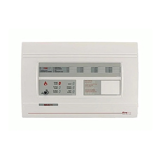
FIRE CONTROL PANEL MAG816 INSTALLATION AND OPERATION MANUAL READ THIS MANUAL BEFORE CONNECTING THE EQUIPMENT AND KEEP IT SAFE FOR FUTURE REFERENCE. To call our technical support line dial: +44 (0) 1527 51 51 50... -
Page 2: Table Of Contents
Installer Instruction GUARANTEE .......................3 1. GENERAL INFORMATION ..................4 2. TECHNICAL SPECIFICATIONS ................4 2.1 general Technical Specifications of MAG816 ...........4 2.2 general Technical Specifications of Relay Module MR8 ......5 3. INSTALLING MAG816 .....................6 3.1 Wall Mounting .....................7 3.2 Flush Mounting ...................7 3.3 Configuration of the Basic Modules ............8... -
Page 3: Guarantee
This manual contains an information about the limitations in using and operation of the product, as and information about the limits in the responsibility of the manufacturer. Please read the operation manual carefully before starting the installation. MAG816 - Installation and Operation Manual... -
Page 4: General Information
EN54 Standard requirements. The panel provides for monitoring and reporting fire events in up to 16 separate zones, depending on the installed configuration. The MAG816 must be installed according to the Fire Alarm Installation Regulations, mandatory for the territory of the respective country. The electrical power supply to the panel must be isolated and must not be capable of being accidentally switched off. -
Page 5: General Technical Specifications Of Relay Module Mr8
• Humidity Up to 93% (non condensing) WARNINGS: Prior to connecting the MAG816 Fire Alarm Panel, perform a thorough test of the all wiring integrity of the entire system. Should a fault arise during installation and connection, which cannot be removed, stop the installation and call the producer or his regional... -
Page 6: Installing Mag816
230 V clamps, to the metal bottom clamps and to the chassis. • After all system programming and testing operation are complete, screw both secure bolts with the help of the hexagonal tool supplied. Figure 1. Figure 2. Figure 3. MAG816 - Installation and Operation Manual... -
Page 7: Wall Mounting
(Positions 17 and 18, page 31) - Figure 7, Position 2. 25mm THICK DRYWALL METAL BOX HANGER SCREWS FOR HANGER FIXING SCREWS FOR FLUSH MOUNTING WASHER Figure 6. Figure 7. MAG816 - Installation and Operation Manual... -
Page 8: Configuration Of The Basic Modules
• 2 - Clamp for supporting the main power supply cable. • 3 - Terminal for connecting between the mains power supply and the power source. T-type fuse 2A (Position 3, page 31). • 4 - Earthing point. MAG816 - Installation and Operation Manual... -
Page 9: Control Module
- Jumper for enable/disable Earth Fault Indication; - Resettable (PTC) fuses; - Connector for connecting the main power source; - Connector for connecting 4-zone / 4-sounder expander; - Connector for connecting the control panel keypad. MAG816 - Installation and Operation Manual... -
Page 10: Main Power Source
Attention: It is possible that the battery might not be charged at the panel initial start-up. In this case the BATT LOW/LOST at the control module and the GENERAL FAULT at the front panel will light on until the battery will be charged up to the required level. MAG816 - Installation and Operation Manual... -
Page 11: 4-Zone Expander
Before connecting or disconnecting the expander you SHOULD check whether the main and the stand-by power supplies are OFF! The metal box of MAG816 can accommodate up to 4 zone expanders. To each zone can be connected up to 32 conventional detectors with consumption <200µA at normal operation mode and unlimited number of manual call points. -
Page 12: 4-Sounder Expander
5 6 7 8 First First Second а) Control First First Second Control 4 Sounder 4 Zone 4 Zone panel 4 Zone 4 Sounder 4 Zones panel Expander Expander Expander Expander Expander Expander Figure 16. MAG816 - Installation and Operation Manual... -
Page 13: Connecting
4. CONNECTING 4.1 Relay Module MR8 MR8 is a supplementary module which is located outside the MAG816 Alarm Panel box. The MR8 contains 8 changeover contact relays. When using all 16 zones, the MAG816 needs two relay modules. The technical specifications of the MR8 module relays are described in item 2.2. - Page 14 Figure 17. Terminals and jumper configuration of MR8. Figure 18. Connecting between Master one Relay Module panel and Master Panel. Figure19. Master Connecting between panel two Relay Modules and Master Panel. MAG816 - Installation and Operation Manual...
-
Page 15: Repeater Panel
4.2 Repeater Panel A second MAG816 can be connected to the MAG816 Fire Alarm panel as Slave. The function of the Slave is to double the light and sound indication and the button control of the first panel at a distance up to 1000 m. For the purpose, to both of the panels have to be assigned specific priorities: The first fire alarm panel shall be the system Master and the second - Slave. -
Page 16: Class Change Mode
- detectors and call points. Example: If there are call points connected in ZONE 1, for the system to function properly there must be a jumper set at its zone expander at z1 position, see also Figure 26. MAG816 - Installation and Operation Manual... - Page 17 Figure 24 shows how to connect the sounders. One R=10K resistor is connected to the end of each circuit as shown in the diagram. LEGEND black brown Figure 24. Connecting of sounders to SND1÷SND4 outputs of the control module and the output of the 4-sounder expander. MAG816 - Installation and Operation Manual...
-
Page 18: System Programming
In case of a false fire alarm the user must press the button to return to normal working mode. In order to program MAG816 for Sounder Delay over an interval between 1 and 10 minutes: • Examine the Table of Instructions for programming sounder delay, shown on Figure 10. -
Page 19: Double Action Mode
The purpose of introducing a DOUBLE Action mode is to avoid false alarms. Where MAG816 has been programmed to function in this mode, in the case of a fire signal, the panel does not alarm at once but waits for the alarm event to be repeated within a specific time interval - Figure 25. -
Page 20: Master Panel Mode
The connection between the Master Panel and the Slave is described in item 4.2. 5.6 Single Panel Mode No jumper is set on the Master or Slave position in Single Panel Mode of the MAG816. In order to program the Single Panel mode: •... -
Page 21: Operation Instructions
ON position (Access Level 2) all buttons are active. - Operation modes LED indication. - LED indication on zone status. - Control buttons. - Instructions for working with the fire panel. MAG816 - Installation and Operation Manual... -
Page 22: Buttons
Lights up in red at Fire in the zone. Lights up in yellow at disabled zone. Blinks in yellow: - 1 blink per second at trouble in the zone; - 2 blinks per second at “One Man” Test and disabling of zones. MAG816 - Installation and Operation Manual... -
Page 23: Sound Signal
“One Man” test mode of zones. The signal can be stopped by pressing the button, but the LED indication remains. 6.6 Service Modes Zone Enable / Disable Each zone of MAG816 can be enabled or disabled. To disable a zone: • Press button: DISABLE/ ENABLE LED blinks. - Page 24 (item 6.1). At this point the sounders are enabled. You can exit the sounder enabling mode also by pressing the button, as in that case the procedure for initial start-up will not run. MAG816 - Installation and Operation Manual...
- Page 25 Man” Test mode is automatic after the end of the test procedure in the last zone, or at any time by pressing button. A sound signalization is activated at every Service Mode entering . The signalization is deactivated by pressing button. MAG816 - Installation and Operation Manual...
-
Page 26: Indication
NORMAL MODE. NOTE: The fault indication does not show immediately. There is a delay in reporting depending on the type of the fault. After all faults are corrected the panel automatically returns to NORMAL MODE. MAG816 - Installation and Operation Manual... -
Page 27: Indication Of The Operation Modes
DISABLE • The respective zone LEDs light up in Disabled yellow to indicate disabled zones. zones and/or • The yellow SOUNDER FAULT/DISA- sounders. BLE LED lights up to indicate disabled sounders. MAG816 - Installation and Operation Manual... -
Page 28: General Connection Circuit Of Mag816
MAG816 - Installation and Operation Manual... -
Page 29: Fire Alarm Record
QUANTITy PER ZONE LOCATION № TOTAL: Ion - Ionisation sensor Ph - Photoelectric sensor RoR - Rate of Rise sensor F/T - Fixed Temperature sensor CP - Call Point System installed by: ..................Telephone/Fax: ..................MAG816 - Installation and Operation Manual... -
Page 30: Service Record
MAG816 - Installation and Operation Manual... -
Page 31: Spare Parts Kits
Self tapping screw М4,2х35 cross slot DIN7981 Jumper Cable tie 2,5/160mm Lightpipe for indication EOL - module Plastic cap 4-Zone Expander MAG816 Spare Parts Kit Screw М3х6 DIN7985 Lightpipe for indication EOL - module Jumper 4-Sounder Expander MAG816 Spare Parts Kit Screw М3х6 DIN7985...
Need help?
Do you have a question about the MAG816 and is the answer not in the manual?
Questions and answers