Table of Contents
Advertisement
Quick Links
Advertisement
Table of Contents

Subscribe to Our Youtube Channel
Related Manuals for ESP MAGPRO9601


Summary of Contents for ESP MAGPRO9601
- Page 1 MAGPRO9601 Addressable Fire Alarm Control Panel Installation Manual 1293...
-
Page 2: Table Of Contents
MAGPRO9601 - Addressable Fire Alarm Panel – Installation Manual Table of Contents 1. INTRODUCTION ................................ 4 1.1. Basic Information ............................4 1.2. Panel General View ........................... 4 1.3. General Specifications ..........................4 1.3.1. General Technical Specifications....................5 1.3.2. Working Environment ......................... 5 1.3.3. - Page 3 The manufacturer reserves the right to change the specifications of the equipment described in that manual without notice. STANDARDS AND CONFORMITY The addressable fire alarm control panel MAGPRO9601 is designed and certified according and with conformity to EN 54 – 2/4 standard. Conforms and approved in accordance with CPR (Construction Products Regulation). 1293...
-
Page 4: Introduction
LAN or RS485 communication protocol. Only one type of connection can be used in a single network. The MAGPRO9601 fire panel is equipped with a back-up supply battery in case of main power supply failure. The built- in 3V pill battery supports the uninterruptable operation of the real-time clock even in case of mains and back-up power supply failure at the same time. -
Page 5: General Technical Specifications
MAGPRO9601 - Addressable Fire Alarm Panel – Installation Manual 1.3.1. General Technical Specifications • Loops - from 1 to 4 loops • Up to 250 devices per one MAGPRO96-L250 Loop expander • Max. number of devices - 1000 • Zone Number - 96 max. - Page 6 MAGPRO9601 - Addressable Fire Alarm Panel – Installation Manual Main power supply In normal operating conditions the fire panel is powered from the mains voltage line. The characteristics of the main power supply are as follows: • Main Power Supply: ............~230VAC +10% / -15% •...
- Page 7 MAGPRO9601 - Addressable Fire Alarm Panel – Installation Manual List of spare parts kits: Element Description MAGPRO9601 Resistor 10K ±5%, 0,25W 2 pcs Jumper 2 pcs Screw 4.2х38, cross slot, DIN7981 (wall mounting – item 2.2) 4 pcs Anchor 6х30mm (wall mounting – item 2.2) 4 pcs Screw M4x40, cross slot, DIN7985 (built-in mounting in 25 mm drywall –...
-
Page 8: Installation
The temperature must be within -5ºС and + 40ºC. The fire panel is not water- proof! Attention: The front cover of MAGPRO9601 panel is mounted to the box bottom with hinges fixed with dismountable rivets. The angle of opening of the front cover must not be greater than 110° - see Figure 3! -
Page 9: Wall Mounting
MAGPRO9601 - Addressable Fire Alarm Panel – Installation Manual 2.2. Wall Mounting • For wall mounting, use the drilling paper template to mark the mounting holes – Figure 4. • For mounting of MAGPRO9601, drill holes Ø6 ÷ Ø8mm. Figure 4 •... -
Page 10: Built-In Mounting
2.3. Built-in Mounting The built-in mounting is designed for MAGPRO9601 panel box and it is applied in 25mm thick drywalls. The built-in mounting is performed with special kit containing: metal base, metal decorative frame and set of fixing elements –... -
Page 11: Module Structures
Place the metal decorative frame over the front door and push forward until it is located around the MAGPRO9601 box bottom. The fixing holes on the back strips of the frame must align with the holes (on the top and bottom side) of the MAGPRO9601 box. The hinges of the front door must be visible after installing the frame. - Page 12 MAGPRO9601 - Addressable Fire Alarm Panel – Installation Manual • Prepare the metal boxes for mounting to each other as remove the plastic caps from the top or bottom side of the box bottom according its position in the module structure. For module structures with three or four panels you have to remove all plastic caps from the boxes mounted into the middle.
-
Page 13: System Components
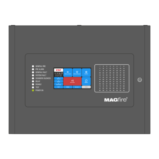
3.1. Front Panel The front panel of MAGPRO9601 presents detailed information of the current system status (1) and activated zones (3) via LED indication. The operation, control and programming of the panel is via the 5 inch TFT screen (2) – Figure 12. -
Page 14: Configuration Of The Basic Modules
Presence of power supply – main or back-up, or both. (green) 3.3. Configuration of the Basic Modules The MAGPRO9601 panel is designed with a range of basic modules organized in factory configuration – Figure 14. Elements’ description: 1 - Main power supply unit - see item 4.1. -
Page 15: Basic Modules Description
MAGPRO9601 - Addressable Fire Alarm Panel – Installation Manual 4. BASIC MODULES DESCRIPTION The MAGPRO9601 is delivered with plug connectors (2- and 3-position) mounted to the PCB of the Loop expander(s). The plug connectors are used for quick wire installation. -
Page 16: Connection Diagram Of Main Power Supply Unit And Back-Up Battery
Ri. 4.2. Outputs Control Module The Outputs Control module in MAGPRO9601 addressable fire alarm panel is a structure of two PCBs mounted to each other via interface slot: Monitored outputs PCB and Programmable Relays PCB. -
Page 17: Connection Of Sounders
MAGPRO9601 - Addressable Fire Alarm Panel – Installation Manual Monitored outputs terminals: Terminal Description +24V DC Auxiliary output, 24VA@0.3A Common earth Monitored output for connecting of a sounder, 24V DC/0.5A Monitored output for connecting of auxiliary devices, 24V DC/0.1A. Fault R This output is deactivated in case of system trouble or fault. -
Page 18: Magpro96-L250 Loop Expander
) of the devices in the communication line in alarm state must be up to 500mA. If the consumption exceeds this value an overload protection would be turned on. In the configuration of MAGPRO9601 addressable fire alarm panel could be mounted up to 4 loop expanders. 4.3.1. Permissible Cable Length The maximum length of the loop in the system could vary according to the cross-section and the ohmic resistance of the used cable. -
Page 19: Loop Expander Elements Description
MAGPRO9601 - Addressable Fire Alarm Panel – Installation Manual 4.3.2. Loop Expander Elements Description 1 - Interface for connection of the loop line – see item 4.3.3. 2 - LED (red) – Indication for power supply of the Loop expander. In normal operation mode it is constantly lighting on. -
Page 20: Adding Loop Expanders
MAGPRO9601 - Addressable Fire Alarm Panel – Installation Manual 4.3.4. Adding Loop Expanders The loop expanders are periphery devices in MAGPRO9601 system configuration. According the physical place of mounting, every loop expander takes a system factory address of periphery device that cannot be changed – see item for general information about the factory addressing of periphery devices. -
Page 21: Main Control Module Pcb
MAGPRO9601 panels support operation with Canon 9 type external printers, models Kafka and Datecs (EP1000), stand-alone devices. You can use only one printer connected to the MAGPRO9601 panel. The type of printer is selected from the installer programming menus at level 3: System-Programming-Panel-Printer. -
Page 22: Network Interface Card
MAGPRO9601 - Addressable Fire Alarm Panel – Installation Manual 4.4.2. Network Interface Card The MAGPRO9601 addressable fire alarm panel is designed with option for connection in a redundant network with other MAGPRO9601, MAGPRO96, MAGPRO16 or MAGPRO-REP Repeater panels (up to 64). The redundant network is based on RS485 interface using network interface card MAGPRO-NIC. - Page 23 MAGPRO9601 - Addressable Fire Alarm Panel – Installation Manual MAGPRO9601 Network Interface Card External power supply unit MAGPRO-REP Figure 26 The maximum cable length between two network modules and/ or repeater panel is 1000m. MAGPRO16 Fire panel MAGPRO9601 Fire panel...
-
Page 24: Lan Connection
(up to 64). The LAN connection can be direct panel-to-panel or by means of a HUB via TCP/IP protocol. To operate in LAN network with other MAGPRO9601, MAGPRO96 and TFT Repeater panels, the installer must set for all panels “LAN” type of the communication protocol. -
Page 25: Supplementary Information
3 to 6 (fixed), but their current number is possible to be changed according the system configuration. The following drawing of the hardware configuration of MAGPRO9601 panel and the table next to it represent the fixed factory addresses of the periphery devices, which must be assumed during the initial power up and programming of the whole system. - Page 26 MAGPRO9601 - Addressable Fire Alarm Panel – Installation Manual The direction of auto-addressing procedure by isolator module, according the positive and negative lines of theMAGPRO96-L250 Loop expander, is shown on Figure 31: End Direction Start Direction Branch 1 MAGPRO96-L250 Loop Controller...
- Page 27 Routine Maintenance MAGPRO9601 control panel does not require any specific maintenance. To clean the panel’s surface, use a dry cloth. Detergents or solvents should not be used to clean the panel and care must be taken that water does not enter the enclosure.
- Page 28 18021322, RevA, 01/ 2024...
Need help?
Do you have a question about the MAGPRO9601 and is the answer not in the manual?
Questions and answers