Westinghouse WGR050NG076 Installation Instructions Manual
High efficiency water heater
Hide thumbs
Also See for WGR050NG076:
Table of Contents
Advertisement
High Efficiency
Water Heater
INSTALLATION
START-UP
MAINTENANCE
PARTS
Models*
WGR050NG076 / WGR060NG076 / WGR080NG076
WGR050LP076 / WGR060LP076 / WGR080LP076
This manual must only be used by a qualified heating installer/service technician. Read and understand all instructions in this manual
before installing. Perform steps in the order given. Failure to comply will result in substantial property damage, severe personal injury,
or death.
Improper installation, adjustment, alteration, service, or maintenance could void product warranty and cause property damage, personal
injury, or death.
NOTICE: Westinghouse reserves the right to make product changes or updates without notice and will not be held liable for
typographical errors in literature.
The surfaces of these products contacted by consumable water contain less than 0.25% lead by weight, as required by the Safe
Drinking Water Act, Section 1417.
NOTE TO CONSUMER: PLEASE KEEP ALL INSTRUCTIONS FOR FUTURE REFERENCE.
WHL-001 REV. 9.3.14
Advertisement
Table of Contents

Subscribe to Our Youtube Channel
Related Manuals for Westinghouse WGR050NG076


Summary of Contents for Westinghouse WGR050NG076
- Page 1 Improper installation, adjustment, alteration, service, or maintenance could void product warranty and cause property damage, personal injury, or death. NOTICE: Westinghouse reserves the right to make product changes or updates without notice and will not be held liable for typographical errors in literature.
- Page 2 IF THE INFORMATION IN THIS MANUAL IS NOT FOLLOWED EXACTLY, A FIRE OR EXPLOSION MAY RESULT, CAUSING PROPERTY DAMAGE, PERSONAL INJURY, OR LOSS OF LIFE. DO NOT STORE GASOLINE OR OTHER FLAMMABLE VAPORS AND LIQUIDS IN THE VICINITY OF THIS OR ANY OTHER APPLIANCE. WHAT TO DO IF YOU SMELL GAS ...
-
Page 3: For The Installer
In some circumstances, the property owner or his/her agent assumes the role, and at government installations, the commanding officer or departmental official may be the AHJ. NOTE: Westinghouse reserves the right to modify product technical specifications and components without prior notice. FOR THE INSTALLER This manual must only be used by a qualified heating installer/service technician. -
Page 4: Table Of Contents
In Canada – CGA No. B149 (latest version), from Canadian Gas Association Laboratories, 55 Scarsdale Road, Don Mills, Ontario, Canada M3B 2R3. Also, Canadian Electrical Code C 22.1, from Canadian Standards Association, 5060 Spectrum Way, Suite 100, Mississauga, Ontario, Canada L4W 5N6. Code for the installation of Heat Producing Appliances (latest version), from American Insurance Association, 85 John Street, New York, NY 11038. - Page 5 PART 5 – VENTING, COMBUSTION AIR AND CONDENSATE REMOVAL................23 A. GENERAL ........................................23 B. APPROVED MATERIALS FOR EXHAUST VENT AND INTAKE PIPE ......................24 C. REQUIREMENTS FOR INSTALLATION IN CANADA ............................ 24 D. EXHAUST VENT AND INTAKE PIPE LOCATION ............................25 E.
-
Page 6: Part 1 - General Safety Information
NOTE: Appliance damage due to flood or submersion is considered an Act of God, and IS NOT covered under product warranty. Altering any Westinghouse appliance with parts not manufactured and/or approved by Westinghouse. WILL INSTANTLY VOID the appliance warranty and could result in property damage, serious personal injury, or death. -
Page 7: Gas
C. GAS Should overheating or gas supply fail to shut off, turn off the manual gas control valve to the water heater. D. WHEN SERVICING THE HEATER To avoid electric shock, disconnect electrical supply before performing maintenance. To avoid severe burns, allow heater to cool. E. -
Page 8: Optional Equipment
The burner flame is ignited by applying high voltage to the system spark electrode. This causes a spark from electrode to ground. C. OPTIONAL EQUIPMENT Below is a list of optional equipment available from Westinghouse: 2” PVC Concentric Vent Kit (Part # KGAVT0501CVT) ... -
Page 9: Part 3 - Prepare Water Heater Location
PART 3 – PREPARE WATER HEATER LOCATION Carefully consider installation when determining heater location. Please read the entire manual before attempting installation. Failure to properly take factors such as heater venting, piping, condensate removal, and wiring into account before installation could result in wasted time, money, and possible property damage and personal injury. -
Page 10: Leveling
Location that could cause the system and heater to freeze and leak. Incorrectly-sized expansion tank 6. Clean and flush system when reinstalling a heater. NOTE: When installing in a zero clearance location, it may not be possible to read or view some product labeling. It is recommended to make note of the heater model and serial number. -
Page 11: Exhaust Vent And Intake Pipe
When raising the heater, fully support the entire bottom of the water heater. Locate or protect the heater so it cannot be damaged by a moving vehicle. E. EXHAUST VENT AND INTAKE PIPE The heater is rated ANSI Z21.10.3 Category IV (pressurized vent, likely to form condensate in the vent) and requires a special vent system designed for pressurized venting. -
Page 12: Prevent Combustion Air Contamination
If the confined space is within a building of tight construction, air for combustion must be obtained from the outdoors as outlined in the Venting section, Part 5 of this manual. When drawing combustion air from the outside into the mechanical room, care must be taken to provide adequate freeze protection. Do not attempt to vent this water heater by any means other than those described in this manual. -
Page 13: Water Chemistry
Chemical imbalance of the water supply may affect efficiency and cause severe damage to the water heater and associated equipment. Westinghouse recommends having water quality professionally analyzed to determine whether it is necessary to install a water softener. It is important that the water chemistry on both the domestic hot water and central heating sides are checked before installing the water heater, as water quality will affect the reliability of the system. - Page 14 Total Dissolved Solids Total Dissolved Solids (TDS) is a measurement of all minerals and solids dissolved in a water sample. The concentration of total dissolved solids is usually expressed in parts per million (ppm). Water with a high TDS concentration will greatly accelerate lime and scale formation in the hot water system. Most high TDS concentrations precipitate out of the water when heated.
- Page 15 Figure 3 – *ALL DIMENSIONS ARE APPROXIMATE UNCRATING HEATER – Any claims for damage or shortage in shipment must be filed immediately against the transportation company by the consignee. COLD WEATHER HANDLING – If the heater has been stored in a very cold location (BELOW 0 F) before installation, handle with care until the plastic components come to room temperature.
-
Page 16: Part 4 - Heater Piping
PERFORMANCE SPECIFICATIONS FOR HIGH EFFICIENCY WATER HEATER MODELS Temperature Rise in Degrees Fahrenheit BTUH Efficiency (°F) (°C) 76,000 Table 2 – Recovery on rating plate is based at 97% thermal efficiency at 70 Fahrenheit rise, as required by ANSI PART 4 – HEATER PIPING Failure to follow the instructions in this section WILL VOID the warranty and may result in property damage, serious injury, or death. -
Page 17: Scalding
B. SCALDING APPROXIMATE TIME / TEMPERATURE RELATIONSHIPS IN SCALDS More than 5 minutes 1 ½ to 2 minutes About 30 seconds About 10 seconds Less than 5 seconds Less than 3 seconds About 1 ½ seconds About 1 second Table 3 This heater can deliver scalding water. -
Page 18: Water Piping
preventers on all incoming water supplies. The hot water expansion tank must be listed for potable water use. The expansion tank should be located on the cold inlet piping close to the water heater. EXPANSION TANK AND MAKE-UP WATER 1. Ensure that the expansion tank is sized to correctly handle heater and system water volume and temperature. Undersized expansion tanks cause system water to be lost from the relief valve, causing make-up water to be added. -
Page 19: Important Notice
The water heater must be full of water and the system fully purged BEFORE powering the water heater. Applying power to the water heater when it is not full of water could result in a condition referred to as “dry-firing”. Dry-firing the water heater will damage the heat exchanger, and could result in property damage, serious personal injury, or death. -
Page 20: Piping Diagrams
J. PIPING DIAGRAMS Figure 4 – High Efficiency Water Heater with Recirculation Line and Thermostatic Mixing Valve Piping NOTES: 1. Minimum pipe size should match unit connection size. Upsize pipe accordingly if greater flow is required. 2. A thermal expansion tank suitable for potable water must be sized and installed within this piping system between the backflow preventer and the cold water inlet. - Page 21 Figure 5 – High Efficiency Water Heater with Air Handler on Side NOTES: 1. Minimum pipe size should match unit connection size. Upsize pipe accordingly if greater flow is required. 2. A thermal expansion tank suitable for potable water must be sized and installed within this piping system between the backflow preventer and the cold water inlet.
- Page 22 – High Efficiency Water Heater with Air Handler on Side Figure 6 NOTES: 1. Minimum pipe size should match unit connection size. Upsize pipe accordingly if greater flow is required. 2. A thermal expansion tank suitable for potable water must be sized and installed within this piping system between the backflow preventer and the cold water inlet.
-
Page 23: Part 5 - Venting, Combustion Air And Condensate Removal
PART 5 – VENTING, COMBUSTION AIR AND CONDENSATE REMOVAL The heater must be vented as detailed in this Venting Section. Ensure exhaust vent and intake piping complies with these instructions regarding vent system. Inspect finished exhaust vent and intake piping thoroughly to ensure all joints are well secured, airtight, and comply with all applicable code requirements, as well as with the instructions provided in this manual. -
Page 24: Approved Materials For Exhaust Vent And Intake Pipe
B. APPROVED MATERIALS FOR EXHAUST VENT AND INTAKE PIPE APPROVED EXHAUST VENT AND INTAKE PIPE MATERIAL Standards for Installation in: Item Material United States Canada PVC schedule 40/80 ANSI/ASTM D1785 PP, CPVC, and PVC venting must be PVC-DWV* ANSI/ASTM D2665 ULC-S636 Certified. -
Page 25: Exhaust Vent And Intake Pipe Location
You must not use “B” vent in an exhaust application. “B” vent is for intake applications ONLY. Using “B” vent in an exhaust application will result in serious injury or death. D. EXHAUST VENT AND INTAKE PIPE LOCATION Figure 7 – ANSI Z223.1 / NFPA 54 for US and CAN/CSA B149.1 for Canada – Exit Terminals for Direct-Vent Venting Systems DETERMINE EXHAUST VENT AND INTAKE PIPE LOCATION –... -
Page 26: Exhaust Vent And Intake Pipe Sizing
The building owner is responsible for keeping the exhaust and intake terminations free of snow, ice, or other potential blockages, as well as scheduling routine maintenance. Failure to keep the vent piping terminations clear and properly maintain the heater could result in property damage, severe personal injury, or death. -
Page 27: Exhaust Vent And Intake Pipe Installation
14. A screened straight coupling is provided with the heater for use as an outside exhaust termination. 15. A screened inlet air tee is provided with the heater to be used as an outside intake termination. Table 7 lists optional exhaust/intake terminations available from Westinghouse: DESCRIPTION STOCK CODE 2”... - Page 28 When installing a combustion air intake from outdoors, care must be taken to utilize uncontaminated combustion air. NOTE: To prevent combustion air contamination, see Table 1 – Contaminant Table. Take extra precaution to adequately support the weight of vent pipes terminating through the roof. Failure to properly support roof terminated vent piping could result in property damage, serious personal injury, or death due to flue gas leakage.
- Page 29 Figure 9 – Venting with Optional Kits (NOT INCLUDED WITH THE WATER HEATER) NOTE: These drawings are meant to demonstrate system venting only. The installer is responsible for all equipment and detailing required by local codes. All vent pipes must be glued, properly supported, and the exhaust must be pitched a minimum of ¼” per foot back to the heater to allow drainage of condensate.
- Page 30 – Figure 10 NOTE: This drawing is meant to demonstrate system venting only. The installer is responsible for all equipment and detailing required by local codes. WHL-001 REV. 9.3.14...
-
Page 31: Venting Through An Existing System
Figure 11 – Horizontal Venting - NOTE: This drawing is meant to demonstrate system venting only. The installer is responsible for all equipment and detailing required by local codes. NOTES: A. For every 1” of overhang, the exhaust vent must be located 1” vertical below overhang (overhang means top of building structure and not two adjacent walls [corner of building]). - Page 32 Do not install the heater into a common existing vent with any other appliance. This will cause flue gas spillage or heater malfunction, resulting in substantial property damage, severe personal injury, or death. Contractors must check state and local codes before installing through an existing vent opening. State and local codes always take precedence over manufacturer’s instructions.
-
Page 33: Indoor Combustion Air Installation In Confined Or Unconfined Space
3. INDOOR COMBUSTION AIR INSTALLATION IN CONFINED OR UNCONFINED SPACE This heater requires fresh, uncontaminated air for safe operation and must be installed in a mechanical room where there is adequate combustion and ventilating air. NOTE: To prevent combustion air contamination, see Table 1 – Contaminant Table on page 12. Combustion air from the indoor space can be used if the space has adequate area or when air is provided through a duct or louver to supply sufficient combustion air based on the water heater input. - Page 34 Figure 14 WHL-001 REV. 9.3.14...
-
Page 35: Condensate Removal System
I. CONDENSATE REMOVAL SYSTEM NOTE: Check with your local gas company to determine if combustion condensate disposal is permitted in your area. In the state of Massachusetts, condensate must be neutralized before entering a drain. This condensing high efficiency water heater has a condensate removal system. Condensate is water vapor derived from combustion products, similar to that produced by an automobile when it is initially started. - Page 36 Figure 16 – Removing and Installing the Condensate Neutralizer NOTICE To ensure proper condensate neutralization it is recommended to check the condensate neutralizer cartridge every two years. Gently shake the cartridge to ensure it is still filled with neutralization media. Replace the condensate neutralizer cartridge if it is empty. Failure to do so could result in improper condensate neutralization.
-
Page 37: Part 6 - Wiring
The heater has the capability of an outdoor reset. Connecting an outdoor sensor allows the heater to operate at optimum efficiency. Westinghouse offers an outdoor sensor. The outdoor sensor must be a 12K NTC sensor. Use a minimum 22 AWG wire for runs of 100 feet or less and minimum 18 AWG wire for runs up to 150 feet. -
Page 38: Internal Wiring Diagram
Label all wires prior to disconnecting them when servicing the heater. Wiring errors can cause improper and dangerous operation. Failure to follow these instructions may result in property damage or personal injury. D. INTERNAL WIRING DIAGRAM Figure 19 – Wiring Diagram PART 7 –... -
Page 39: Gas Piping
The gas supply shall have a maximum inlet pressure of less than 14" water column (350 mm), ½ pound pressure (3.5 kPa), and a minimum of 3.5" water column. The entire piping system, gas meter and regulator must be sized properly to prevent pressure drop greater than 0.5"... -
Page 40: Gas Valve
It is recommended that a soapy solution be used to detect leaks. Bubbles will appear on the pipe to indicate a leak is present. The gas piping must be sized for proper flow and length of pipe to avoid excessive pressure drop. Both the gas meter and the gas regulator must be properly sized for the total gas load. -
Page 41: Part 8 - Controls
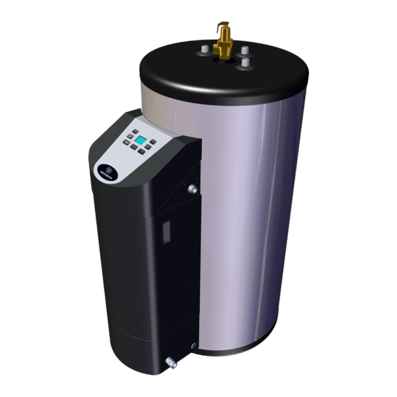
PART 8 – CONTROLS A. CONTROL AND DISPLAY OVERVIEW Detailed Description of Button Functions 1. Setting Adjust Down 2. Setting Adjust Up 3. Decreases the User Setpoint 4. Increases the User Setpoint 5. ECO Mode 6. RESET 7. OFF / Mode Enable Figure 22 –... -
Page 42: Basic Control Functions
ECO Mode Putting the water heater into ECO Mode reduces maximum ECO On / Off (Off) firing rate to 80% of the rated maximum firing rate. This increases water heater efficiency in times of low hot water demand. Press to put the water heater into ECO mode. Press again to return to normal operation. -
Page 43: Changing User Setpoint
4. CHANGING USER SETPOINT Press either once to change the User Setpoint. The normal operation screen will clear and be replaced by a flashing number. This is the User Setpoint. F. The setpoint range is 70 – 160 Press to decrease or to increase the setpoint. -
Page 44: Outdoor Reset
To enter Installer Mode, press and hold for five seconds. When the ( ) screen appears, Installer Mode is active. Press this screen to access the Technical Service Parameters codes (P00, P01, etc.). To change parameter value, press once. The value will appear. Press to decrease or to increase the value. -
Page 45: Inquiry Mode And Navigation
Connect the outdoor sensor to the terminals marked “outdoor”. Press at this screen to access the Technical Service Parameters codes (P00, P01, etc.). Press to advance through the parameters. Press to return to the previous parameter. Go to P06 Enter desired MIN Outdoor Temp value Press to advance to the next parameter. -
Page 46: Reset Mode And Navigation
To enter Installer Mode, press and hold for five seconds. When the ( ) screen appears, Installer Mode is active. Press twice to find History Mode. The control is ready to access the History Mode when the following screen appears on the display. Press at this screen to access the History Mode codes (H01, H02, etc.). -
Page 47: Part 9 - Start-Up Procedure
PART 9 – START-UP PROCEDURE FOR YOUR OWN SAFETY READ BEFORE OPERATING 1. This water heater does not have pilot. It is equipped with an ignition device which automatically lights the burner. Do not try to light the burner by hand. 2. -
Page 48: Maintenance
Test mode can be used to incrementally increase and decrease fan speed to test the combustion system. See Tables 15 and 16 for Combustion Settings and Fan Speeds. 1. Use the push buttons to change the fan speed (steps of 50 rpm) between the range maximum fan speed and minimum fan speed 2. -
Page 49: Part 10 - Shutdown
PART 10 – SHUTDOWN A. SHUTDOWN PROCEDURE If the burner is not operating, lower the set point value to 70 F and wait for the burner to shut off. Continue to wait for the combustion blower to stop, so all latent combustion gases are purged from the system. This should take a maximum of 300 seconds (5 minutes). B. - Page 50 3. Press the key to clear the fault and resume operation. Be sure to observe the operation of the unit to prevent a recurrence of the fault. NOTE: You are allowed up to 5 “resets” to clear a Fault or Error code. After that, the controller will enter an |E13| Lockout state.
- Page 51 CONTROL BOARD LOCKOUT FAULTS CODE SHORT DESCRIPTION LONG DESCRIPTION CORRECTIVE ACTION The control senses no flame after Is the gas turned on to the water heater? three ignition attempts. Manually reset the water heater. Observe water heater operation. If fault code occurs again Check for stable gas pressure.
- Page 52 The data received from the tank Manually reset the water heater. sensors exceeds the difference Observe water heater operation. If fault code occurs allowed by the control. again Check the Dual Temperature Sensor. Ensure it is properly wired to the control, and that there are no breaks, cuts, or other visible issues with the sensor wire.
- Page 53 Figure 25 – Replacement Parts WHL-001 REV. 9.3.14...
- Page 54 Figure 26 – Replacement Parts WHL-001 REV. 9.3.14...
-
Page 55: Part 12 - Maintenance
PART 12 - MAINTENANCE In unusually dirty or dusty conditions, care must be taken to keep water heater cabinet door in place at all times. Failure to do so VOIDS WARRANTY! Allowing the water heater to operate with a dirty combustion chamber will hurt operation. Failure to clean the heat exchanger as needed by the installation location could result in water heater failure, property damage, personal injury, or death. - Page 56 Clean. Set gap at ¼”. Clean probe with plumbers cloth to Spark Electrode remove oxides. Combination Ignitor Check ionization in uA (i04 in the Inquiry Mode menu). and Flame Probe Record high fire and low fire. Clean probe with plumbers cloth to remove oxides.
- Page 57 WHL-001 REV. 9.3.14...
- Page 58 WHL-001 REV. 9.3.14...
-
Page 59: Maintenance Notes
MAINTENANCE NOTES WHL-001 REV. 9.3.14... -
Page 60: Customer Installation Record Form
Customer: Please only sign after the installer has reviewed the installation, safety, proper operation and maintenance of the system. In the case that the system has any problems, please call the installer. If you are unable to make contact, please contact your Westinghouse Sales Representative. Distributor/Dealer: Please insert contact details.
Need help?
Do you have a question about the WGR050NG076 and is the answer not in the manual?
Questions and answers