Table of Contents
Advertisement
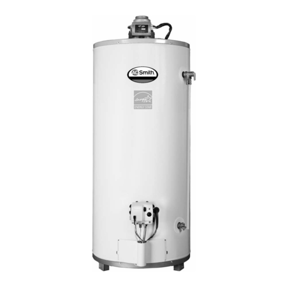
ATMOSPHERIC VENTED WATER HEATER
WARNING:
Improper installation, adjustment, alter-
ation, service, or maintenance can cause
injury or property damage. Refer to this
manual. For assistance or additional infor-
mation, consult a qualified installer, serv-
ice agency, or the gas utility.
FOR YOUR SAFETY
• Do not store or use gasoline or other
flammable vapours and liquids in the
vicinity of this or any other appliance.
• Installation and service must be per-
formed by a qualified installer, service
agency or the gas utility.
WARNING:
If the information in these instructions is
not followed exactly, a fire or explosion
may result causing property damage, per-
sonal injury or death.
WHAT TO DO IF YOU SMELL GAS
• Do not try to light any appliance.
• Do not touch any electrical switch; do
not use any phone in your building.
• Immediately call your gas supplier from
a neighbor's phone. Follow the gas
supplier's instructions.
• If you cannot reach your gas supplier,
call the fire department.
INSTALLATION AND
OPERATING INSTRUCTIONS
Read these instructions thoroughly before starting
PART NO. 320221-000 Rev 00 (12-05)
Advertisement
Table of Contents

Related Manuals for A.O. Smith ATMOSPHERIC VENTED WATER HEATER


Summary of Contents for A.O. Smith ATMOSPHERIC VENTED WATER HEATER
-
Page 1: Operating Instructions
INSTALLATION AND OPERATING INSTRUCTIONS Read these instructions thoroughly before starting ATMOSPHERIC VENTED WATER HEATER WARNING: Improper installation, adjustment, alter- ation, service, or maintenance can cause injury or property damage. Refer to this manual. For assistance or additional infor- mation, consult a qualified installer, serv- ice agency, or the gas utility. -
Page 2: Table Of Contents
TABLE OF CONTENTS I) INTRODUCTION ......3 IV) OPERATING INSTRUCTIONS ....15 User Responsibilities Water Temperature Regulation II) SAFETY. -
Page 3: I) Introduction
Your safety and the safety of others is very important. We have provided many important safety messages in this manual and on your appliance. Always read and obey all safety messages. This is the safety alert symbol. This symbol alerts you to potential hazards that can kill or hurt you and others. All safety messages will follow the safety alert symbol and either the word “DANGER”... -
Page 4: Safety Warning (Flammable Vapours)
Safety Warning (Flammable Vapours) can cause soot build-up or present a fire hazard, and may result in serious bodily harm or death from asphyxiation. MAKE SURE THE FLOW OF COMBUSTION AND VENTI- W ARNI NG LATION AIR IS NOT RESTRICTED. DANGER Carbon Monoxide Warning •... -
Page 5: Iii) Installation
• III) INSTALLATION How and where to obtain combustion and ventilation air supply; See “Air Requirements”. Unpacking the Water Heater • Routing and support of the vent piping. • Position of water supply and placement of water piping WARNING Excessive Weight Hazard for hot and cold water;... -
Page 6: Gas Supply
Shield (see Figure 2). This Shield reflects heat from the affect the proper operation of the water heater. Special High-input heaters to prevent damage to combustible floors. attention must be given to conditions these devices may The Shield is held in place by three (3) tabs that rest on the create. -
Page 7: Gas Pressure
Gas Pressure Gas line purging Gas line purging is required to eliminate air from the piping WARNING system. Purging should be performed by persons experi- Exposure to a higher gas supply pressure enced in this type of gas service in compliance with the may cause damage to the control, resulting code having jurisdiction. -
Page 8: Air Requirements
Air Requirements Important: Air for combustion and ventilation must not come from a corrosive atmosphere. Any failure due to cor- rosive elements in the atmosphere is excluded from war- ranty coverage. Installations in or for certain places including, but not limited PERMANENT to, those listed below will require outdoor air for combustion OPENINGS... -
Page 9: U.s. Installations
Confined Space Air Requirements for U.S. Installations Refer to Figure 6 (a), (b), (c) or (d) for proper sizing and location of combustion air ducts and openings. CHECK LOCAL CODES. PERMANENT (a) Equipment located in confined spaces; all air from OPENINGS inside the building. -
Page 10: Exhaust Venting
Exhaust Venting Hook the tab leg of the drafthood into the slot in the heater’s Vent Pipe System top or the flue damper if the heater is equipped with a flue damper. Align the remaining legs with the hole/dimples and This water heater is a Category 1, non-direct vented appli- secure the drafthood to the top with three screws as shown ance. -
Page 11: Union Connections
Mixing Valves the installation drawing (Figure 10). If the indoor installation area is subject to freezing temperatures, the water piping WARNING must be protected by insulation. Water supply pressure Never allow small children to use a hot-water should not exceed 550 kPa (80psi). If this occurs a pressure reducing valve and/or an expansion tank may be required. -
Page 12: Temperature And Pressure (T&P) Relief Valve
The Discharge Line: check valve. This will create a closed water system. During • the heating cycle of the water heater, the water expands Must not be smaller than the pipe size of the relief valve causing pressure inside the water heater to increase. This or have any reducing coupling installed in the discharge may cause the temperature and pressure relief valve to dis- line. -
Page 13: Wrap-Around Filter Installation
Wrap-around Filter Installation Important: A Wrap-around Filter has been included with the water heater. For correct operation it is essential that this fil- ter be installed properly. If you encounter difficulty installing the filter or have a question, please call your qualified serv- ice technician. -
Page 14: Electrical Supply
Electrical Supply WARNING Electrical Shock Hazard • Disconnect power before servicing. • Replace all parts and panels before operating. • Failure to do so can result in electrical shock. 24 Volt Control precautions (Applies to Honeywell control equipped heaters only). Important: The electrical controls used inside the gas con- trol/thermostat of this water heater are polarity sensitive. -
Page 15: Installations Check
Installations Check IV) OPERATING INSTRUCTIONS Check Here Water Temperature Regulation Have the safety precautions described in the manual been implemented? HOT WATER CAN SCALD: Water heaters are intended to produce hot water. Water heated to a temperature that will Does the gas piping conform to the recom- satisfy space heating, clothes washing, dish washing, and mendations of your Gas Utility Company? other sanitizing needs can scald and permanently injure you... -
Page 16: Temperature Adjustment
Temperature Adjustment GAS CONTROL 49°C (120°F) MARK The thermostat of this water heater has been factory set at KNOB its lowest position. It is adjustable and must be set to the desired temperature setting. The preferred starting point is 49°C (120°F). Turn the water temperature dial clockwise to decrease the temperature, or counterclockwise increase the temperature. -
Page 17: Lighting Instructions (White-Rodgers 37C)
Lighting Instructions (White-Rodgers 37C) FOR YOUR SAFETY READ BEFORE OPERATING POUR VOTRE SÉCURITÉ LISEZ AVANT DE METTRE EN MARCHE WARNING: AVERTISSEMENT If you do not follow these : Quiconque ne respecte pas à la instructions exactly, a fire or explo- lettre les instructions dans la présente notice risque sion may result causing property de déclencher un incendie ou une explosion entraî-... -
Page 18: Lighting Instructions (Honeywell 24 Volt)
Lighting Instructions (Honeywell 24 Volt) FOR YOUR SAFETY READ POUR VOTRE SÉCURITÉ, LISEZ BEFORE LIGHTING ATTENTIVEMENT AVANT L’ALLUMAGE WARNING: AVERTISSEMENT: If you do not follow Tout manquement aux présentes these instructions exactly, a fire or directives peut causer un incendie ou une explosion explosion may result causing property résultant en des dommages matériels, des blessures ou damage, personal injury or loss of life. -
Page 19: V) Operation
Checking the Draft V) OPERATION Burner Flames After successfully lighting the water heater, allow the unit to operate for 15 minutes and check the drafthood relief open- Inspect the burner flames through the viewport and com- ing for proper draft. Pass a match flame around the relief pare them to the drawings in Figure 20. -
Page 20: Water Heater Sounds
Water Heater Sounds Anode/Water Odour During the normal operation of the water heater, sounds or Each water heater contains at least one anode, which will noises may be heard. These noises are common and may slowly deplete while protecting the glass-lined tank prolong- result from the following: ing the life of the water heater. -
Page 21: Water Heater Operation (24 Volt Only)
Water Heater Operation (24 Volt only) LED FLASH SEQUENCE CONTROL STATUS Thermostat calls for heat Short flash once IDLE (no call for heat, Within 15 seconds: every four seconds no fault conditions) • Vent damper rotates to open position "Heartbeat", alternates Call For Heat •... -
Page 22: Vi) Maintenance
Periodic Inspection VI) MAINTENANCE Periodically a visual inspection should be made of the vent- The installation and maintenance of the water heater must ing and air supply system, piping systems, main burner, comply with all of the instructions described in sections I to pilot burner and flame arrestor. -
Page 23: Temperature And Pressure Relief Valve
Temperature and Pressure Relief Valve 4. Verify if the quick connects are firmly inserted in the TCO switch contacts. Manually operate the temperature and pressure relief valve 5. Replace the outer door. at least once a year to make sure it is working properly. To 6. -
Page 24: 24 Volt Honeywell Control Service
24 Volt Honeywell Control Service Some heaters covered by this manual come equipped with a 24 volt vent damper and a Modular Honeywell Gas Control. Both the Electronic Control Module and the Valve Module of this control may be changed without the need to disconnect the threaded control fitting from the body of the water heater. -
Page 25: Temperature Sensor And Cable Replacement
Temperature Sensor and Cable Replacement Do not remove the entire gas control assembly from the water heater. To remove the Temperature Sensor and Cable: 1. Remove the Electronic Control Module as outlined above. Note: When removing the control module from the gas con- trol assembly, care is required to disengage the pins on the valve module. -
Page 26: Vii) Combo Heating
VII) COMBO HEATING 4. If the space heating water system requires water with temperatures in excess of 60°C (140°F), a mixing valve, This section serves as a guide for the installation and use of or other means to temper the water and reduce scald “Combo”... -
Page 27: Viii) Troubleshooting Guide
VIII) TROUBLESHOOTING GUIDE Note: Troubleshooting must be done by qualified service personnel familiar with the start up and check out procedure. Note: The latest version of the installation and operating instructions manual can be found at www.johnwoodwater- heaters.com PROBLEM CORRECTION POSSIBLE CAUSE(S) 1. - Page 28 PROBLEM CORRECTION POSSIBLE CAUSE(S) 1. Insufficient secondary air 1. Provide ventilation to water heater. Check flue way, flue baffle, burner COMBUSTION ODOURS 2. Flue clogged 2. Clean, locate source and correct 3. Heater installed in a confined area 3. Provide fresh air ventilation 1.
-
Page 29: Ix) Repair Parts Illustration
IX) REPAIR PARTS ILLUSTRATION 1. NIPPLE-HOT OUTLET 2. NIPPLE-COLD INLET 3. DRAFTHOOD 4. TEMPERATURE & PRESSURE RELIEF VALVE 5. REDUCER RING 6. ANODE 7. DIP TUBE 8. FLUE BAFFLE 9. DRAIN VALVE 10. BURNER/MANIFOLD ASSEMBLY 11. GAS CONTROL/THERMOSTAT 12. OUTER DOOR 13. - Page 30 14. TCO SWITCH 17. PILOT/THERMOCOUPLE ASSEMBLY 18. VIEWPORT 19. TWO PIECE GROMMET WITH CLIP 20. MANIFOLD DOOR 21. GAS MANIFOLD 22. PILOT TUBE 23. GAS ORIFICE 24. MANIFOLD DOOR GASKET 25. BURNER Figure 35 Manifold/Door Assembly (LP) 14. TCO SWITCH 15.
- Page 31 This page intentionally left blank. May be used for notes or to record other installation information. – 31 –...
- Page 32 599 Hill Street West Fergus, ON Canada N1M 2X1 PHONE: 1-888-479-8324 www.hotwatercanada.ca / email: techsupport@hotwater.com...
Need help?
Do you have a question about the ATMOSPHERIC VENTED WATER HEATER and is the answer not in the manual?
Questions and answers