Table of Contents
Advertisement
Quick Links
By
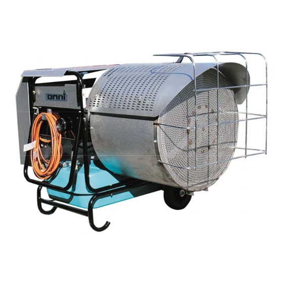
WASTE OIL FIRED MOBILE RADIANT HEATER
Operation and Service Instructions
Manual
MODEL OWR-150
Thank you and congratulations on your purchase of an Omni Waste Oil Fired Mobile
Radiant Heater. You have selected a high quality, precision-engineered piece of
equipment, designed to give you many benefits as well as years of outstanding
performance.
♦
♦
♦
♦
Econo Heat
5714 1st Avenue
Spokane Washington 99212.
(509)534-1022
www.econoheat.com
100267 Rev A2
Advertisement
Table of Contents

Subscribe to Our Youtube Channel
Related Manuals for Omni OWR-150


Summary of Contents for Omni OWR-150
- Page 1 Manual MODEL OWR-150 Thank you and congratulations on your purchase of an Omni Waste Oil Fired Mobile Radiant Heater. You have selected a high quality, precision-engineered piece of equipment, designed to give you many benefits as well as years of outstanding performance.
- Page 2 NOTES: The instructions contained in this manual apply to the operation and service of Omni Waste oil fired mobile radiant heaters. The following instructions should be carefully followed for obtaining the best possible installation, operation and service conditions.
- Page 3 NOTICE TO OWNER AND INSTALLER To enjoy the long term benefits of burning your used oil in an Omni Waste Oil Burning appliance, it is necessary to become familiar with the correct operation and maintenance of your new heater. Before operating this appliance, make sure you read and understand this manual.
-
Page 4: Specifications
SPECIFICATIONS BTU’S/HR OUTPUT 150,000 GALLONS PER HOUR VOLTAGE 120V 60Hz REQUIREMENTS Single Phase AMPS FULL LOAD 8.4 A WEIGHT 180 LBS TANK CAPACITY 10.6 Gallons DIMENSIONS L/W/H 50”x28”x34” Notes: All illustrations and specifications contained herein are based on the latest information available at the time of publication approval. - Page 5 Figure 2 – Inclination 34” 50” Figure 3 – Dimension Operation and Service Instructions...
-
Page 6: Wiring Diagram
WIRING DIAGRAM PREHEATER BLOCK CONTROLLER Oil Valve Power Switch 500W Fuse HEAT BLOWER TIMER Power Plug THERMO- COUPLE Delay Timer METAL PREHEATER HIGH BLOCK LIMIT SWITCH BLOWER MOTOR HIGH VOLTAGE OIL PRIMARY CONTROL TRANS- THERMOSTAT RADIANT HEATER FORMER (IE, Honeywell, etc.) CONNECTION PHOTO EYE FLAME SENSOR... -
Page 7: Oil Burner
OIL BURNER Oil Primary Igniter Control Transformer Air Pressure Adjuster Air Band (Combustion Air Supply Compressor Adjustment) Air Pressure Gauge Power Oil Pressure Indicator Indicator Gauge Figure 4 – Oil Burner (Back View Closed) Operation and Service Instructions... - Page 8 Pre-Heater Control Circuit Board Oil Pre-Heater Block Muffler/Filter Photo Eye Electrical Flame Sensor Terminal Block Transformer Igniter Springs Heater Electrical Schematic Figure 5 – Oil Burner (Back View Opened) Electrodes Oil Valve Nozzle Burner Motor Flame Cone Figure 6 – Oil Burner (Front View) Operation, and Service Instructions...
-
Page 9: Oil Burner Technology
Figure 7 – Radiant Heater (Back View) OIL BURNER TECHNOLOGY Omni’s patented burner technology improves the efficiency of the oil burn process by continuous stabilization of the oil viscosity. Optimum atomization (spray) is accomplished by precisely pre- heating the oil and air prior to introduction to the combustion chamber. The waste oil enters into... - Page 10 ADJUSTMENT REQUIRED unless in high altitudes application where minor adjustment may be required. • Oil Primary Control: (figure 4) Controls the oil burner ignition. Checks for flame in the combustion chamber, if no flame is detected within 45 seconds, the oil primary will shutdown the oil burner.
-
Page 11: Initial Start Procedure
• Power Indicator: (figure 4) Indicates when power is present at the burner. • Run Indicator: (figure 4) Indicates that the burner is ready for operation after the initial pre-heat time of approx. 5 minutes from initial power up. • Fuel Pump: (figure 7, 13) pumps fuel from fuel tank to burner. -
Page 12: Maintenance Schedule
To Adjust Lift Cap Up Combustion To Lock Push Cap Down Chamber Flame Burner Fuel Regulator Back Side of Burner ¾ Length of Combustion Chamber Figure 8 – Flame Adjustment Figure 9 – Fuel Regulator MAINTENANCE SCHEDULE WEEKLY --- Drain water from storage tank. MONTHLY --- clean stainless filter screen in filter (figure 14) periodically and drain off any water accumulation. - Page 13 ELECTRODE ADJUSTMENTS Electrodes are adjusted at time of manufacture. However, they should be check periodically and at time of installation to be sure they are set as noted in the following dimensional drawing. Swing burner door back for inspection. (figure 5, 10, 11) CAUTION: UNPLUG HEATER BEFORE CHECKING OR ADJUSTING ELECTRODE SETTING.
- Page 14 Electrodes Pre-Heater Control Card Nozzle Thermocouple Figure 12 – Pre-Heater Block Detail (Removed From Burner for Clarity) Strainer Filter Housing Pump Gasket Washer Allen Bolts (4) Bolt & Washer Filter Housing Pump Pump Cover Stainless Filter Screen Figure 13 – Fuel Pump Figure 14 –...
- Page 15 Operation and Service Instructions...
-
Page 16: Troubleshooting
TROUBLE SHOOTING ♦Most Likely •Less Likely ♣Least Likely Symptom Cause Remedy 1. Heater shuts off ♦Manual reset ♦Requiring manual restart by reset button on. 2. Loss of prime overnight ♦Vacuum air leak in fuel line ♦Check all fuel connections. Tighten fittings. Won’t hold vacuum ♣Plugged pump screen ♣... - Page 17 7. Heater rumbles and ♦Pump setting wrong ♦Pump not functioning properly-over firing. May need RPM excessive heat blow back readjust. Reset flame slightly less than ½ way down tube from flame vision port. combustion chamber. Use adjustment knob on pump motor. (See Figure 7).
- Page 18 Omni Radiant Heater Limited Warranty Econo Heat (manufacturer) warrants to the purchaser of the Radiant Heater listed above will be free from defects in materials and workmanship for the durations specified below, which duration begins on the date of delivery to the customer. Customer is responsible for maintaining proof of date of delivery.
- Page 19 WARRANTY CARD Please fill our, tear off and return to manufacturer Return following warranty information to manufacturer within thirty (30) days of purchase or warranty will not be valid. (Please print or type). Date of Purchase_____________________________________________________________________ Serial #__________________________ Model ____________________________________________ Customer Name_____________________________________________________________________ Address____________________________________________________________________________ City _________________________ State ________________ Zip Code ________________________...
Need help?
Do you have a question about the OWR-150 and is the answer not in the manual?
Questions and answers