
Related Manuals for Liebert NETWORK POWER SWITCH 2


Summary of Contents for Liebert NETWORK POWER SWITCH 2
- Page 1 AC Power For Business-Critical Continuity ® ™ Liebert NETWORK POWER SWITCH 2 Installation Manual – 7,3 KVA – 230V –32A – 2 Pole...
- Page 3 Please accept our thanks for giving us the privilege to serve you by choosing a Liebert make product. If this is your first Liebert product, we hope it is the beginning of a long relationship which delivers value to your organisation. If you already own and use a Liebert product, we are doubly honoured by your decision of continuing this relationship.
- Page 4 User Manual Information for the protection of the environment 1.Unit servicing: this unit makes use of components dangerous for the environment (electronic cards, electronic component). The components removed must be taken to specialized collection and disposal centers. 2.Unit dismantling: in case of unit dismantling, this operation shall be carried out by specialized personnel. The unit must be taken to centers specialized in collection and disposal of dangerous substances.
- Page 5 Fax +39 049 9719053 mailto:serviceUPS.LiebertEMEA@emerson.com While every precaution has been taken to ensure accuracy and completeness in this manual, Liebert Corporation assumes no responsibility and disclaims all liability for damages resulting from use of this information or for any errors or omissions.
-
Page 6: Table Of Contents
User Manual Table of Contents Chapter 1 – General description ..........................1-1 Introduction................................1-1 Design Concept..............................1-1 Mechanical Design Description ...........................1-2 Mimic Indications ..............................1-3 Manual Bypass Switch Operation ........................1-4 Potential free contacts............................1-5 Chapter 2 – Operating Instructions..........................2-1 Introduction................................2-1 General Notes................................2-1 Procedure for Switching the Network Power Switch to power the load from a Power Off condition....2-2 Switching the Load to Manual Bypass condition ....................2-2 Procedure for switching the Network Power Switch from Manual Bypass condition to Normal Operation ..2-3 Chapter 3 –... - Page 7 User Manual This manual describes the following equipment: EQUIPMENT PART NUMBER 7,3kVA, 230V, 32A, 2 Pole Network Power Switch SSWITCH2-32A Support Information: If you require assistance for any reason, please have the following information available: Model and size Serial number Date installed Location Voltage &...
-
Page 8: Chapter 1 - General Description
User Manual Chapter 1 - General Description 1 Chapter 1 – General description 1.1 Introduction The Network Power Switch (NPS) is an automatic static transfer switch designed to provide fast automatic transfers between two independent, synchronous/asynchronous AC power sources to provide continuity of AC power to critical equipment, such as information technology equipment. -
Page 9: Design Concept
User Manual Chapter 1 - General Description 1.2 Design Concept Fig 1.2 - Power Circuit Diagram for Network Power Switch Figure 1.2 shows the Power circuit diagram for Network Power Switch. Source 1 & Source 2 are the two synchronized/unsynchronized power sources with fuse switches FS1 & FS2 & pair of SCR’s TA1 & TB1 in series with each path &TA2 and TB2 in the neutral path Logic dictates that at any time only one pair of back-to-back connected SCR’s in the line and neutral should conduct. -
Page 10: Mechanical Design Description
User Manual Chapter 1 - General Description 1.3 Mechanical Design Description Fixed unit Hotswap unit Manual Bypass Switch Lock Telescopic Slides Fig 1.3 – Hotswap and Fixed Unit The Network Power Switch consists of two modules. The fixed unit consists of the input and output connections and manual bypass transfer control switch. The second module is hot swappable plug-in type with removable electronics &... -
Page 11: Mimic Indications
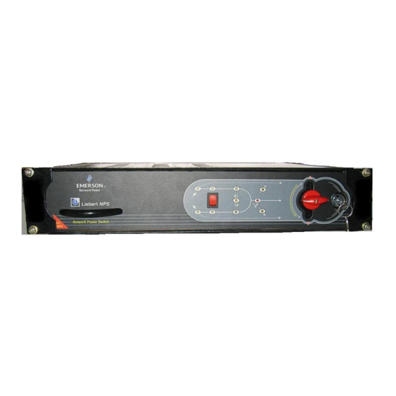
User Manual Chapter 1 - General Description 1.4 Mimic Indications S1 Healthy S1 Priority S1 Feeding Load on S1 Priority Selection Overload Switch Load on S2 Unsynchronised transfer S2 Healthy S2 Priority S2 Feeding Fig 1.4 – Mimic and LED Indications LED INDICATION Mimic indications: Ten LED’s are mounted on the mimic plate;... -
Page 12: Manual Bypass Switch Operation
User Manual Chapter 1 - General Description 1.5 Manual Bypass Switch Operation Load feed through source 1 BYPASS Load feed through NPS OUTPUT Load feed through source 2 BYPASS Fig 1.5 – Manual Bypass Switch Operation Manual Bypass switch is used only when a fault occurs in the Network Power Switch and the control circuitry of the Network Power Switch is to be checked. -
Page 13: Potential Free Contacts
User Manual Chapter 1 - General Description Pull out the Hot swappable sliding module out of the Network Power Switch, which contains SCR • assembly and control circuitry. Operating Network Power Switch in Normal Mode (load connected to Network Power Switch output) Insert the Hot swappable module into the Network Power Switch unit •... -
Page 14: Chapter 2 - Operating Instructions
User Manual Chapter 1 - General Description Optional: 1NO + 1NC Auxiliary contact block stackable to siemens circuit breaker Auxilliary Backfeed indication contact: Note : a) The line shows PFC inside NPS b) The numbers indicated in the boxes are wire numbers coming to PFC terminals 2 Chapter 2 –... -
Page 15: Procedure For Switching The Network Power Switch To Power The Load From A Power Off Condition
User Manual Chapter 1 - General Description 2.3 Procedure for Switching the Network Power Switch to power the load from a Power Off condition This procedure should be followed when turning on the Network Power Switch from a fully powered down condition -i.e. -
Page 16: Procedure For Switching The Network Power Switch From Manual Bypass Condition To Normal Operation
User Manual Chapter 1 - General Description 2.5 Procedure for switching the Network Power Switch from Manual Bypass condition to Normal Operation Unlock the Bypass switch using the key provided. Rotate the bypass switch knob to the Static switch output position, i.e. horizontal position. Lock the Bypass Switch, remove the key and keep it in original place. -
Page 17: Connecting Cables To Network Power Switch
User Manual Chapter 1 - General Description Fig 3.1 – NPS Installation 3.3 Connecting cables to Network Power Switch WARNING BEFORE CABLING-UP THE NETWORK POWER SWITCH, ENSURE THAT YOU ARE AWARE OF THE LOCATION AND OPERATION OF THE EXTERNAL ISOLATORS THAT CONNECT THE NETWORK POWER SWITCH INPUT SUPPLY TO THE MAINS DISTRIBUTION PANEL. -
Page 18: Cable Rating
User Manual Chapter 1 - General Description 3.3.2 Cable Rating Following are the recommended cable size for 7,3kVA Network Power Switch – Table 3-1 Description Max. Current rating (Amp) PVC cable (mm Max Cable (mm Input Cables 3G10 Output Cables 3G10 Signalization&coil drive 10 x 0,25 **... -
Page 19: Safety Earth
User Manual Chapter 1 - General Description Fig 3.4 – External Power Cables 3.3.4 Safety earth The safety earth terminal is provided on the rear side of equipment .The safety earth cable of the inputs and the output must be connected to this terminal. WARNING FAILURE TO FOLLOW ADEQUATE EARTHING PROCEDURES CAN RESULT IN ELECTRIC SHOCK HAZARD TO PERSONNEL, OR THE RISK OF FIRE, SHOULD AN EARTH FAULT OCCUR. -
Page 20: Cabling Procedure
User Manual Chapter 1 - General Description These isolators must have an average sensitivity, possibly adjustable between 10mA and 0.3A; further more the intervention of the RCD’s have to be delayed of > 90 ms. Output to the System: In the event that an external distribution panel is used for load distribution, the selection of protective device must provide discrimination with those that are used at the input to the Network Power Switch module. -
Page 21: Fixing Of Hotswap Unit
User Manual Chapter 1 - General Description Right Telescopic Slide Left Telescopic Slide Fig 3.5 – Removal of Hotswap unit 3.4.2 Fixing of Hotswap unit After ensuring the Hotswap unit is in good ready-to-use condition, it has to be fitted back into the Network Power Switch. -
Page 22: Chapter 4 - Specifications
User Manual Chapter 4 – Specifications 4 Chapter 4 – Specifications 4.1 Conformity and Standards This equipment complies with the following requirements: Normative references: Safety: * EN 62310-1 EMC: * EN62310-2 The equipment must be installed in accordance with these instructions and used only with accessories approved by the manufacturer to maintain conformity with the standards. -
Page 23: Electrical Specifications
User Manual Chapter 4 – Specifications 4.4 Electrical Specifications ELECTRICAL UNITS DESCRIPTION CHARACTERISTICS Nominal Input Voltage 220, 230 or 240 volts singe phase, 3W+G, 50 Hz. Solidly grounded Volts power sources Nominal Output current Amps Frequency 50 / 60 Guaranteed Transfer to alternate source within –15 % of Vnominal Source unhealthy status Load Power factor range 0.5 to unity leading or lagging... -
Page 24: Installation Drawings
User Manual Installation Drawings 5.1.1 Power Circuit Diagram – Controller PCB 5.1.2 Power Circuit Diagram – RC Snubber PCB 5.1.3 External Power cable connections 5.1.4 Overall general arrangement 5.1.5 Connection of the external isolators utilizing users external power supply 5.1.6 External Power Supply realization for 230VAC shunt trip coils 5.1.7 External Power Supply realization for low voltage AC shunt trip coils 5.1.8 External Power Supply realization for DC shunt trip coils 5.1.9 Circuit breaker selection chart... - Page 25 User Manual Chapter 5 – Installation Drawing 5.1.1 Power Circuit Diagram – Controller PCB (08/10) Page 5-2...
- Page 26 User Manual Chapter 5 – Installation Drawing 5.1.2 Power Circuit Diagram – RC Snubber PCB (08/10) Page 5-3...
- Page 27 User Manual Chapter 5 – Installation Drawing 5.1.3 External power cable connections Rear View EXTERNAL POWER CABLE CONNECTION NETWORK POWER SWITCH (08/10) Page 5-4...
- Page 28 User Manual Chapter 5 – Installation Drawing 5.1.4 Overall general arrangement (08/10) Page 5-5...
- Page 29 User Manual Chapter 5 – Installation Drawing 5.1.5 Connection of the external isolators utilizing users external power supply The shunt trip coil voltage has to be available when any of the source inputs of NPS is available. For recommended coil supply realisation see figures below: For 230VAC shunt trip coils connection see 5.1.6 For low voltage AC shunt trip coils see 5.1.7 For DC shunt trip coils see 5.1.8...
-
Page 30: External Power Supply Realization For 230Vac Shunt Trip Coils
User Manual Chapter 5 – Installation Drawing 5.1.6 External Power Supply realization for 230VAC shunt trip coils (08/10) Page 5-7... - Page 31 User Manual Chapter 5 – Installation Drawing 5.1.7 External Power Supply realization for low voltage AC shunt trip coils (08/10) Page 5-8...
- Page 32 User Manual Chapter 5 – Installation Drawing 5.1.8 External Power Supply realization for DC shunt trip coils (08/10) Page 5-9...
-
Page 33: Circuit Breaker Selection Chart
User Manual Chapter 5 – Installation Drawing 5.1.9 Circuit breaker selection chart Resistive load Light inductive load Heavy inductive load PRODUCT Protection Solid Neutral Standard Solid Neutral Standard Solid Neutral Standard SSWITCH2-25A Circuit Breaker 1pole 32A char.B 2pole 32A char.B 1pole 32A char.C 2pole 32A char.C 1pole 32A char.D... -
Page 34: Limited Warranty
If the Liebert NPS fails to conform with the above warranty within the two year warranty period, Liebert will repair or replace the system, at Liebert's option. Repairs or replacements are warranted for the remainder of the original warranty period. - Page 36 7/F, Dah Sing Financial Centre All rights reserved throughout the world. Specifications subject to 108 Gloucester Road, Wanchai change without notice. ® Liebert is a registered trademark of Liebert Corporation. Hong Kong All names referred to are trademarks Tel: +852 2572220...
Need help?
Do you have a question about the NETWORK POWER SWITCH 2 and is the answer not in the manual?
Questions and answers